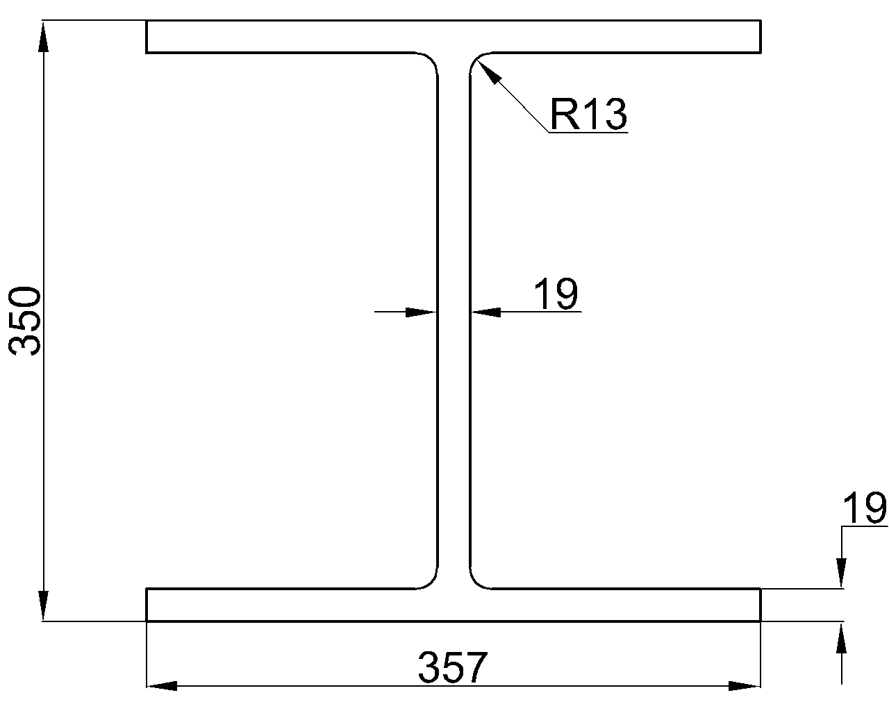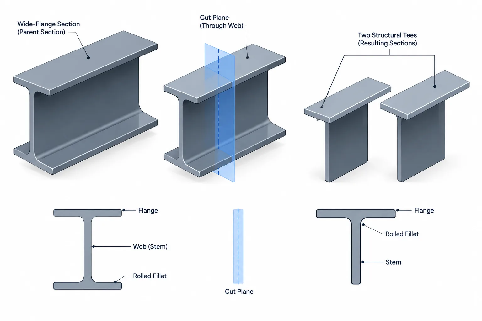
Structural tees are commonly associated with the WT, MT, and ST designations found in steel shape tables. Their geometry corresponds to a tee produced by dividing a compatible W, M, or S section through its web. That relationship is useful, but it can also create a misleading assumption: a fabricated split tee is not simply a perfect half-section that can be modeled without considering the cut.
The parent shape, cutting path, kerf, straightening needs, end connections, and procurement method can all affect the finished member. Designers and detailers should therefore distinguish between a published tee shape and a project-specific tee cut from a larger section.
What Is a Split Structural Tee?
A split structural tee consists of one flange and a portion of the web from an I-shaped parent section. In tee terminology, the remaining web is usually called the stem. The flange and stem form an unsymmetric open section with one principal geometric direction passing through the stem centerline.
Shape families indicate the general parent-section relationship:
- WT: a structural tee associated with a W-shape parent.
- MT: a structural tee associated with an M-shape parent.
- ST: a structural tee associated with an S-shape parent.
The family letters matter because the parent sections have different flange and web geometry. A tee should not be substituted solely because another tee has a similar overall depth or nominal weight. Flange slope, flange width, stem thickness, fillet geometry, centroid location, and section properties may differ.
Published Tee Shape vs. Fabricated Split Member
A published tee designation identifies a recognized section with tabulated dimensions and properties. A fabrication drawing may instead instruct a shop to split a specific I-shape. Those two descriptions can be related, but they do not communicate exactly the same information.
| Issue | Published tee designation | Project-specific split instruction |
|---|---|---|
| Section identity | References a defined tee entry in a shape table | References the actual parent section to be cut |
| Properties | Uses the published properties for the designated tee | May require properties based on the specified finished geometry |
| Cut location | Implied by the listed tee geometry | Must be shown or otherwise clearly controlled |
| Kerf and finish | Not a fabrication instruction | Can affect finished stem depth and edge condition |
| Availability | Still requires supplier confirmation | Depends on availability of the parent shape and shop capability |
If the engineering documents call for a designated WT, the detailer should not quietly replace it with a generic note to split a W-shape. Conversely, if the documents require a tee cut from a particular parent member, substituting a catalog tee can change both geometry and properties. The intended product should be resolved before shop drawings are released.
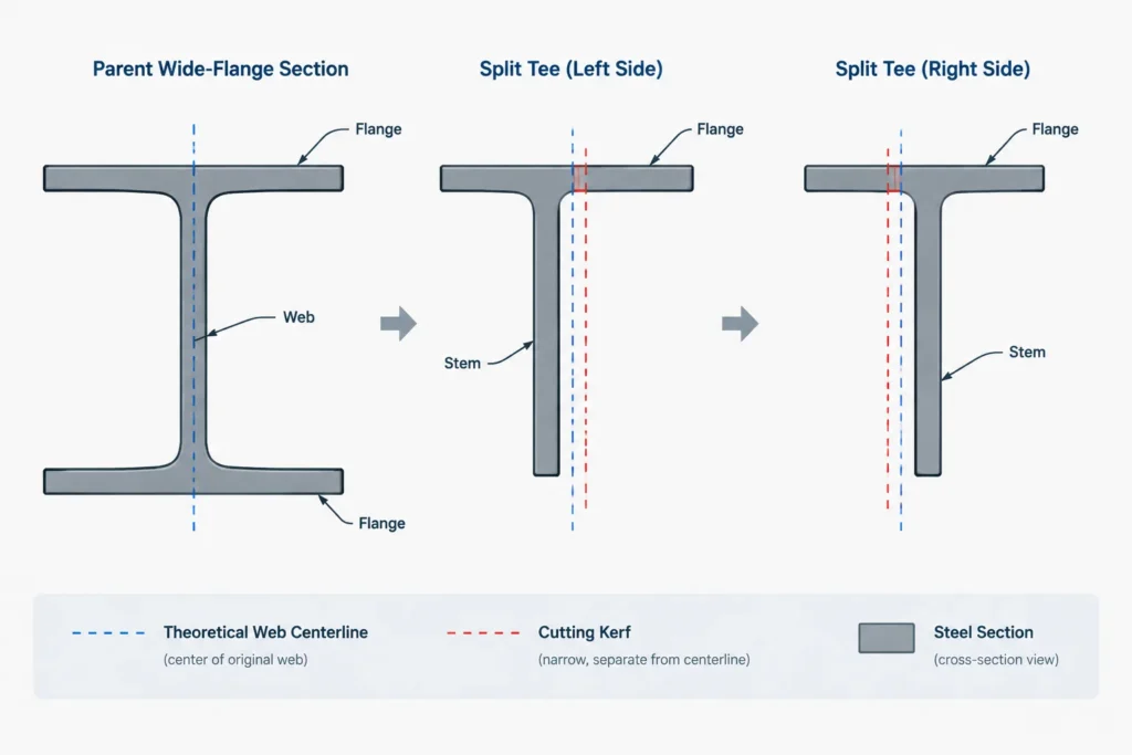
The Cut Line Is Part of the Geometry
When an I-shape is divided longitudinally, the theoretical split line commonly follows the web centerline. A real cutting process removes material, however. Saw width, thermal-cutting kerf, cleanup, and edge preparation can influence the final stem depth.
Several questions should be answered in the fabrication model or drawing:
- Is the cut centered in the parent web?
- Is the stated tee depth nominal, minimum, or a finished dimension?
- Which side of the layout line receives the kerf?
- Does the cut edge require grinding, machining, beveling, or another finish?
- Will both resulting tees be used, or is only one finished member required?
- Are straightness and distortion controls important to connection fit-up?
A centerline drawn through a CAD model has no width. A shop cut does. This difference may be unimportant for a schematic model but can matter when the stem edge fits against another plate, establishes an assembly depth, or receives a weld preparation.
Why the Two Resulting Tees May Need Coordination
Dividing one parent shape can produce a pair of companion tees, sometimes informally treated as sister pieces. A centered straight cut is intended to produce matching members, but actual fabrication conditions can introduce variation. Parent-shape tolerances, sweep, camber, residual stresses, cutting heat, and subsequent straightening may affect the pieces.
Thermal cutting can also release residual stresses and cause curvature or twist. This does not mean splitting is unsuitable; it means the detailing and fabrication plan should recognize that the finished pieces may need inspection or correction before connection components are fitted.
If the two tees are intended to work as a coordinated pair, piece marks should remain unambiguous. Match-marking can be useful where the members return to opposite sides of the same assembly or where hole patterns are handed.
Section Properties Do Not Follow a Simple Half-Value Rule
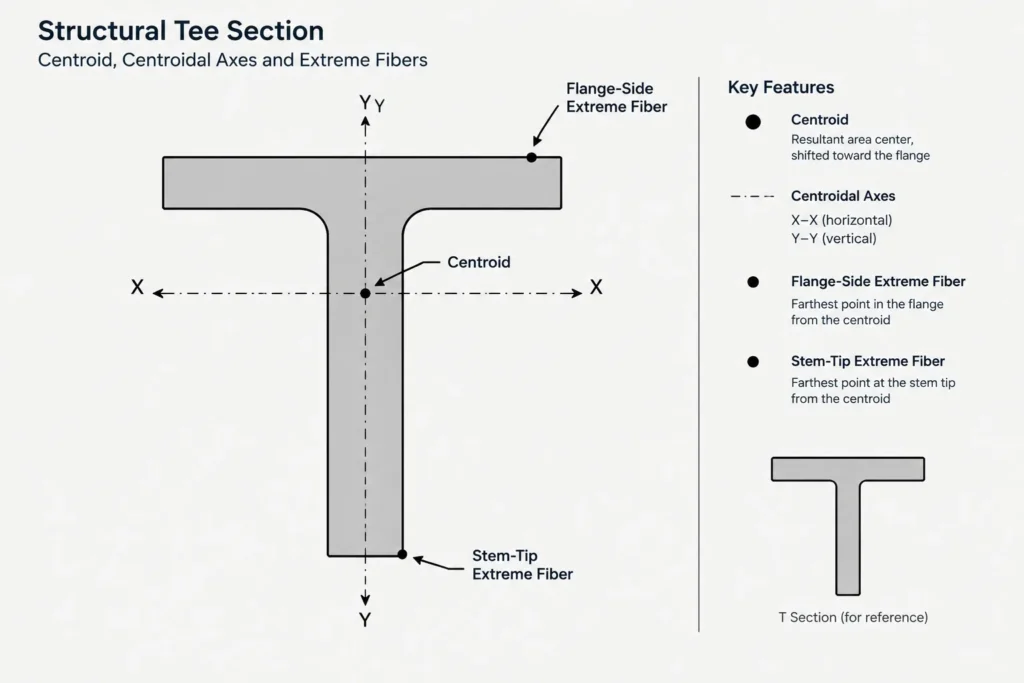
Some quantities appear easy to infer from the parent I-shape, but tee behavior must be evaluated about the tee’s own centroidal and principal axes. The tee centroid shifts toward the flange rather than remaining at the parent section’s center.
As a result:
- The tee’s moment of inertia about a centroidal axis is not generally obtained by halving the corresponding parent value.
- Elastic section modulus can differ on the flange side and stem-tip side because their extreme-fiber distances are different.
- Radius of gyration must use the tee’s own area and moment of inertia.
- Torsional and warping properties should come from an appropriate published source or a verified section analysis.
- Principal-axis properties may be relevant when the tee is loaded or braced away from its conventional orientation.
For a standard designated tee, use verified properties for that tee rather than deriving them casually from the parent. For a custom split location, reduced stem, cope, slot, or other modification, the net finished section may require a separate calculation.
Connection Detailing at the Flange and Stem
The flange and stem provide distinctly different connection surfaces. A flange connection may offer a broad face for bolts, welds, bearing, or attachment plates. A stem connection resembles a web connection but must account for the tee’s one-sided flange geometry and nearby root fillets.
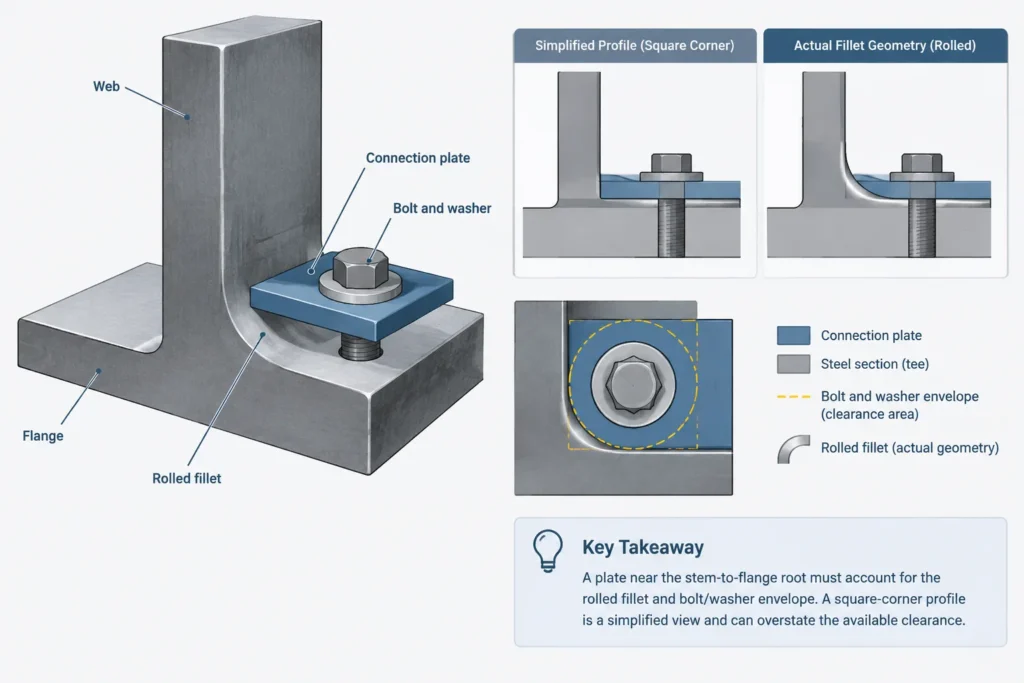
Check the root region
The intersection of the stem and flange is not a sharp inside corner. Rolled fillets occupy space that can interfere with plates, weld access, bolt heads, nuts, and washers. A simplified square-corner CAD profile may therefore indicate clearance that does not exist on the actual section.
Control the stem-tip reference
Dimensions taken from the cut stem edge can be sensitive to the finished cut. Where practical, the drawing should identify whether connection geometry is controlled from the flange face, member work line, tee centroid, or stem tip. Do not mix these references without showing how they relate.
Consider unsymmetric attachment
A load introduced through only the flange or only one face of the stem may be eccentric to the tee centroid or shear center. Connection layout, bracing, and member orientation should follow the structural design rather than drafting convenience.
CAD Modeling Workflow for a Split Tee
A reliable model should preserve both design identity and fabrication intent. One practical workflow is:
- Confirm whether the member is a standard tee designation or a custom split section.
- Insert or build the parent profile from verified shape data when the parent controls procurement.
- Establish the longitudinal cutting plane explicitly.
- Model kerf or finishing allowances only when they are known and relevant; otherwise flag them for coordination.
- Retain the actual rolled fillet region where connection clearance is being checked.
- Assign the member axis and insertion point consistently, such as flange face, stem centerline, centroid, or work line.
- Check end cuts, holes, copes, weld preparations, and attached plates against the finished tee rather than the unsplit parent.
- Label the part with its specified designation or parent-and-cut instruction, not merely a generic tee description.
A visually accurate model is not automatically a verified section-property model. If CAD software calculates properties from a simplified profile, compare the profile assumptions with the published or engineered section before using the results.
Drawing Information That Prevents Ambiguity
A split-tee detail should communicate more than its outline. Depending on the project, useful information may include:
- The tee designation or exact parent-shape designation.
- The cut path and whether it is centered or offset.
- The controlling finished depth when critical.
- Required edge finish or weld preparation.
- Member orientation, including flange direction.
- Work points, setbacks, and end-cut references.
- Hole and attachment locations from stable datums.
- Piece-mark relationships between companion tees.
- Any required coordination for straightening, inspection, or trial fit.
Notes should not imply that every member produced from a split is interchangeable unless the design and fabrication documents support that conclusion.
Procurement and Substitution Checks
Before detailing is finalized, confirm whether the specified tee can be sourced directly or will be fabricated from a parent section. Local availability, quantity, length, cutting capability, and schedule can influence the practical choice, but substitutions require technical review.
When comparing alternatives, recheck the overall dimensions, flange geometry, stem thickness, fillet clearance, weight, centroid, section properties, connection fit, member orientation, and any architectural exposure requirements. Similar-looking tees are not automatically structurally or dimensionally equivalent.
Practical Takeaway
A split structural tee should be treated as both a structural section and a fabricated product. Shape tables describe its nominal geometry and properties, while shop documents must explain how the actual member is obtained, oriented, cut, and connected. Keeping those two viewpoints aligned helps prevent incorrect section-property assumptions, stem-depth conflicts, root-fillet clashes, and procurement surprises.