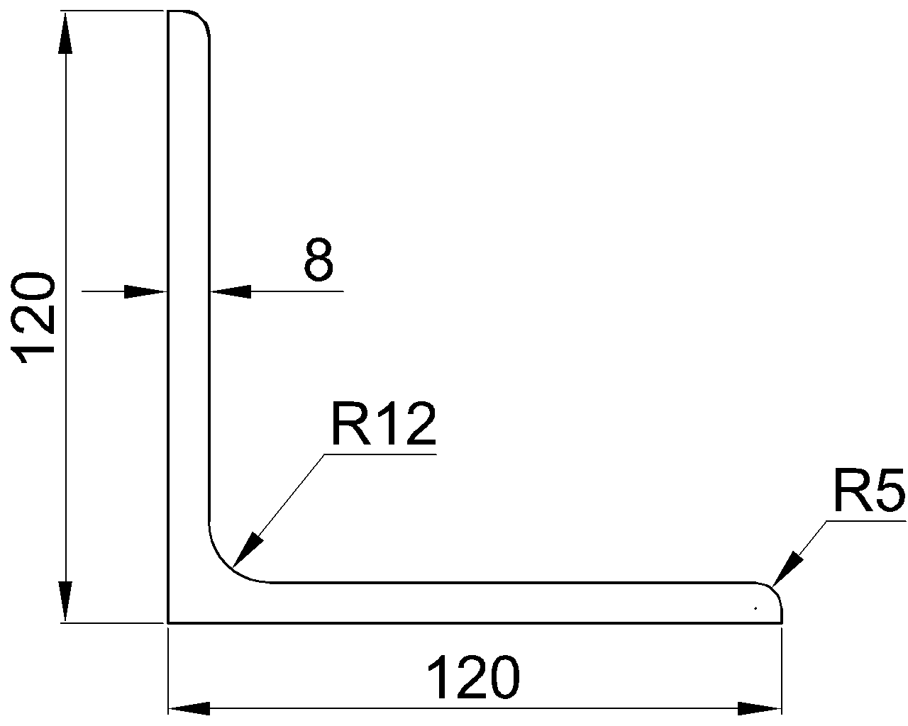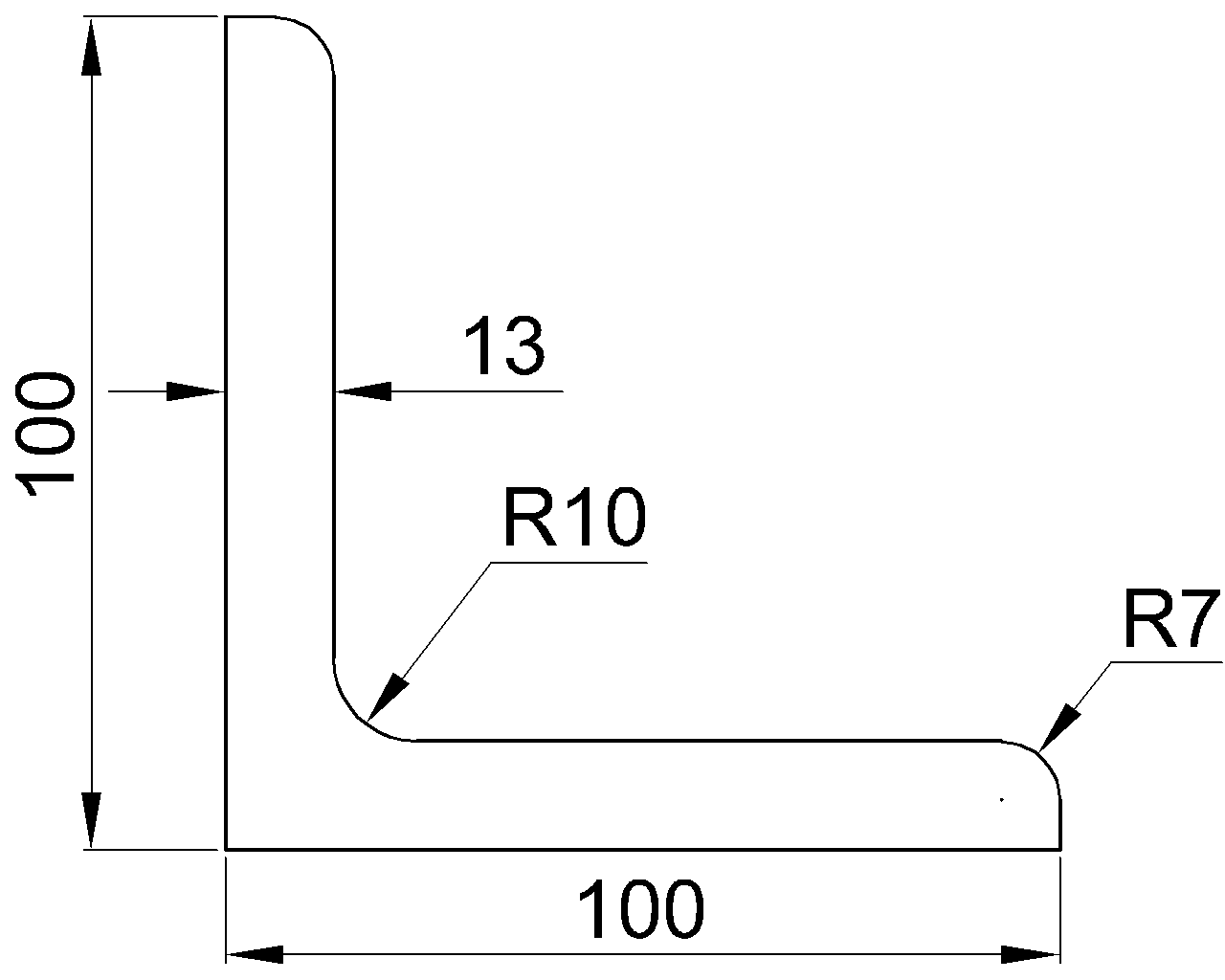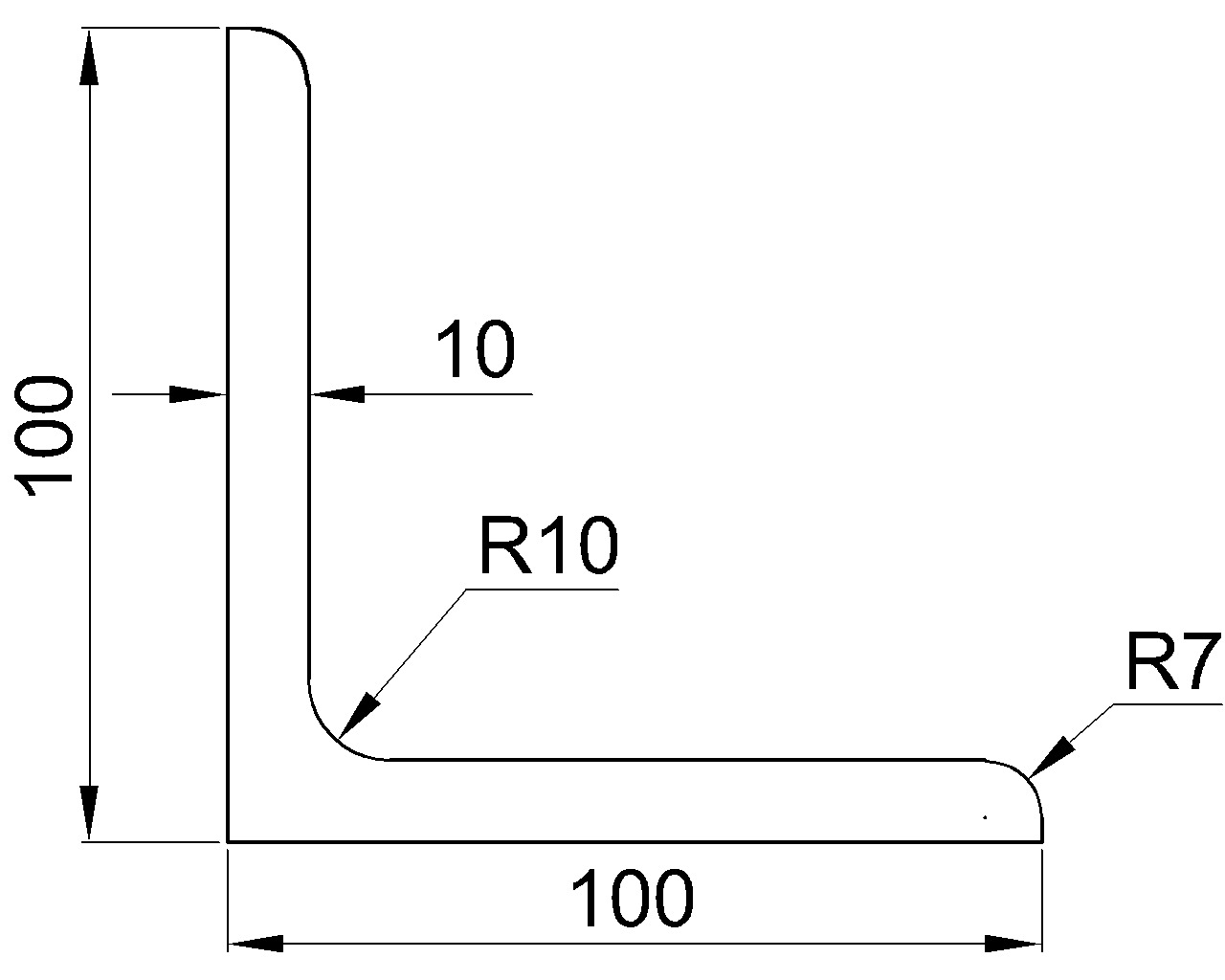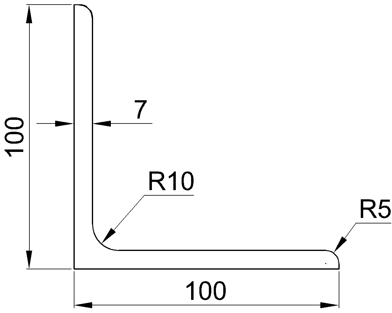
The centroid is a familiar reference point in structural steel shape tables and CAD models. It defines the geometric center of area and is used to establish section axes, calculate bending properties, and position member geometry. The shear center is a different point: it identifies where a transverse load can act without producing twist under the assumptions of elastic beam behavior.
For some steel sections, the centroid and shear center occupy the same location. For others—especially open, unsymmetric shapes—the two points can be separated significantly. That separation helps explain why a channel, angle, or tee may rotate when loaded, even when the load appears to be applied near the visual middle of the member.
What the centroid represents
The centroid is the geometric center of the cross-sectional area. If a section is divided into component areas, the centroid is the area-weighted average location of those components. Its position depends only on cross-sectional geometry, not on the direction or location of an applied load.
Section properties such as moments of inertia and section moduli are commonly reported about centroidal axes. In a CAD profile, placing the origin at the centroid can therefore simplify property calculations and comparison with published shape data.
The centroid is also the point through which an axial force must act to avoid first-order bending from load eccentricity. This axial-load role should not be confused with the shear center’s role under transverse loading.
What the shear center represents
The shear center is the cross-sectional point through which a transverse shear load can act without causing the section to twist. When the load does not pass through that point, its offset creates a torsional moment about the member’s longitudinal axis.
In simplified form, the twisting tendency is associated with the transverse force multiplied by its perpendicular eccentricity from the shear center. Establishing the actual response may also require consideration of torsional stiffness, warping, restraints, load distribution, connection behavior, and member boundary conditions.
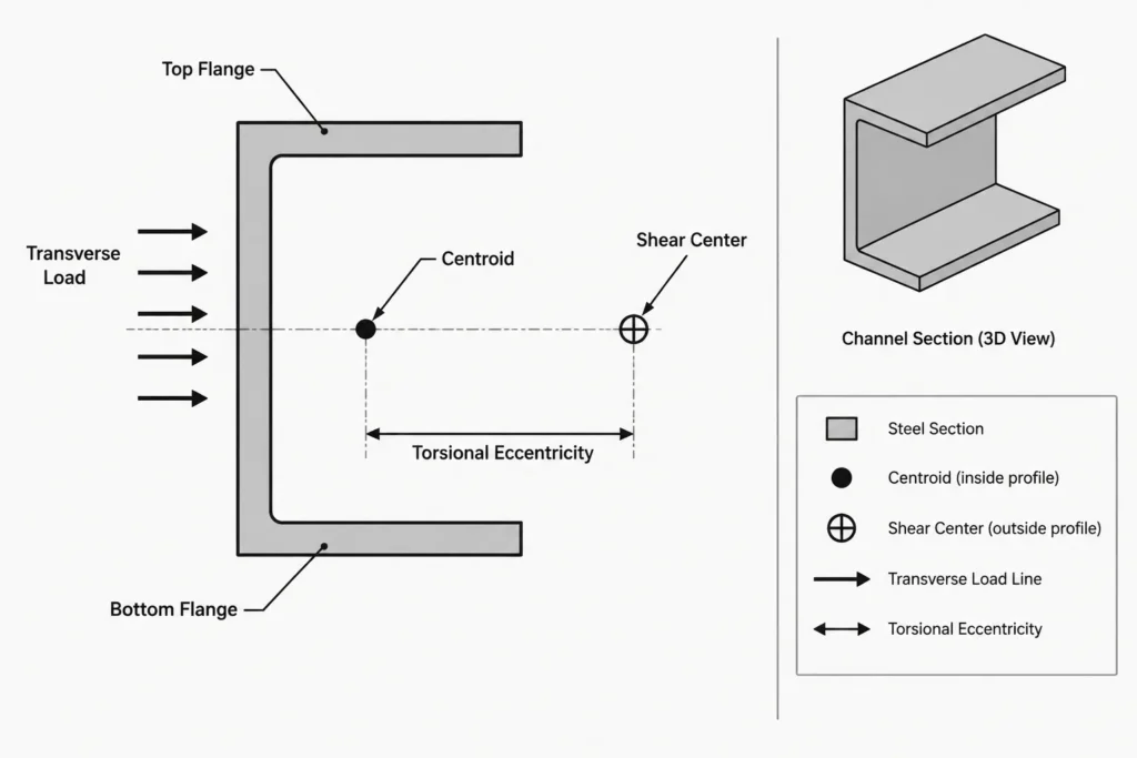
The shear center is a cross-sectional property rather than a material point that must lie inside the steel. For many open shapes, it is located outside the physical profile.
When the two points coincide
Cross-sectional symmetry provides a useful first check:
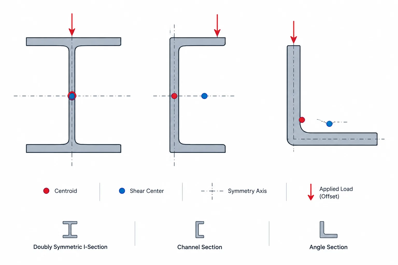
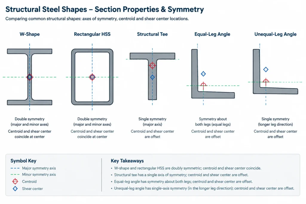
- Doubly symmetric sections: The shear center and centroid coincide at the intersection of the two symmetry axes. Typical idealized examples include many W-shapes and rectangular or square HSS.
- Singly symmetric sections: The shear center must lie on the axis of symmetry, but it does not necessarily coincide with the centroid. Channels and structural tees are important examples.
- Sections without an axis of symmetry: The shear center is not constrained to a symmetry line. Unequal-leg angles and many built-up sections require more careful evaluation.
Symmetry is a geometry test, not a complete assessment of member behavior. Connections, concentrated loads, offsets, openings, and attached elements can still introduce torsion into a member whose centroid and shear center coincide.
How common structural steel shapes behave
| Shape type | Centroid and shear-center relationship | Practical observation |
|---|---|---|
| W-shape or other doubly symmetric I-section | Generally coincide | A load through the web plane is commonly aligned with both points, provided there is no lateral offset. |
| Rectangular or square HSS | Generally coincide | Closed geometry also provides substantially different torsional behavior from an open section. |
| Round HSS or pipe-like circular section | Coincide at the center | Rotational symmetry makes the central reference visually direct. |
| Channel | Separated; both lie on the section’s symmetry axis | The shear center is typically outside the section on the side behind the web, opposite the flange tips. |
| Structural tee | Both lie on the stem symmetry axis but may not coincide | A connection at the flange or stem can introduce an offset from the shear center. |
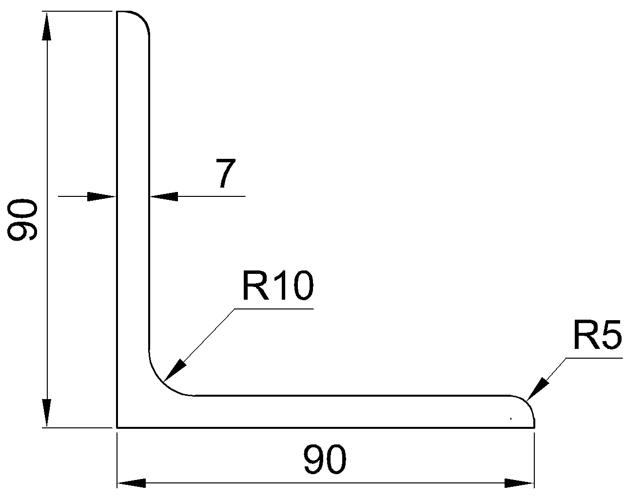
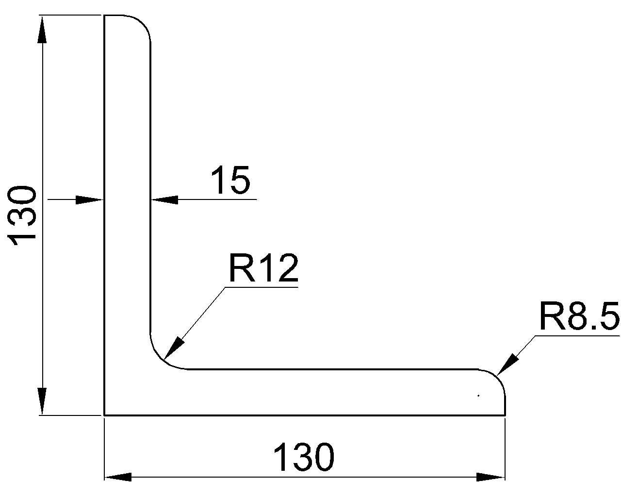
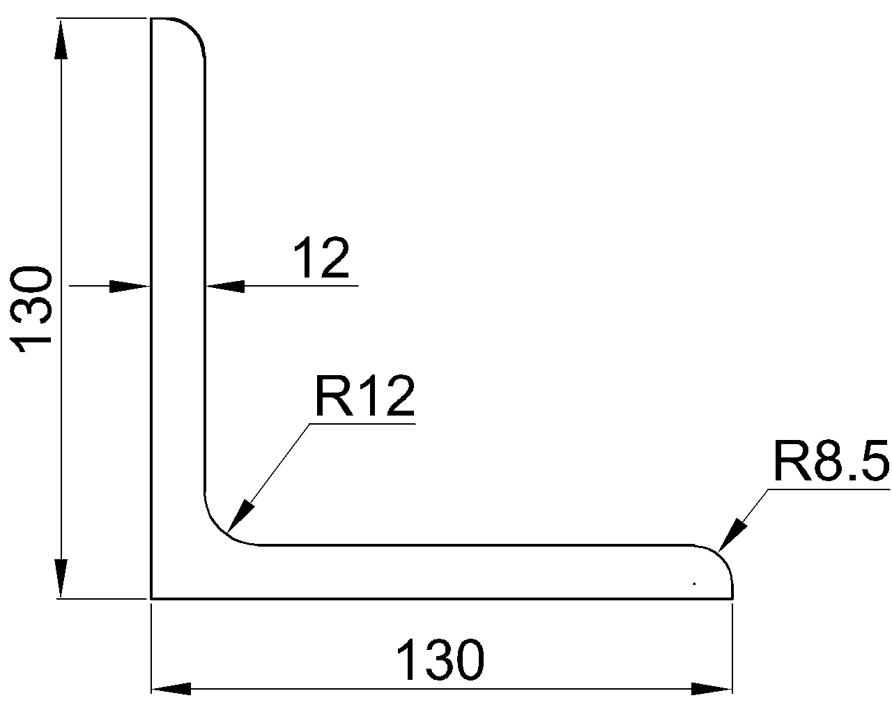
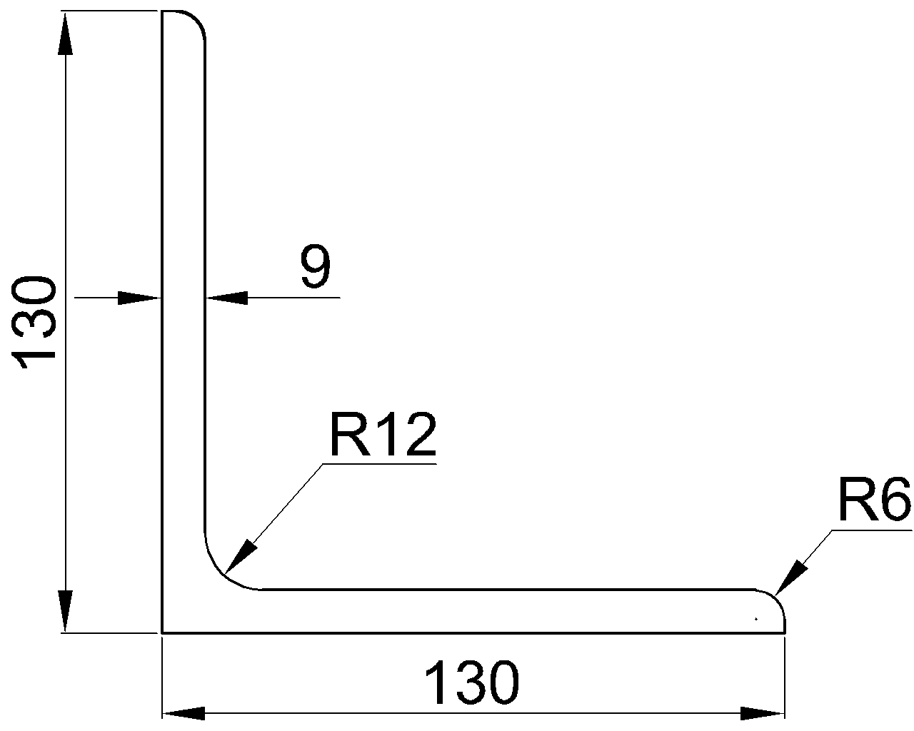
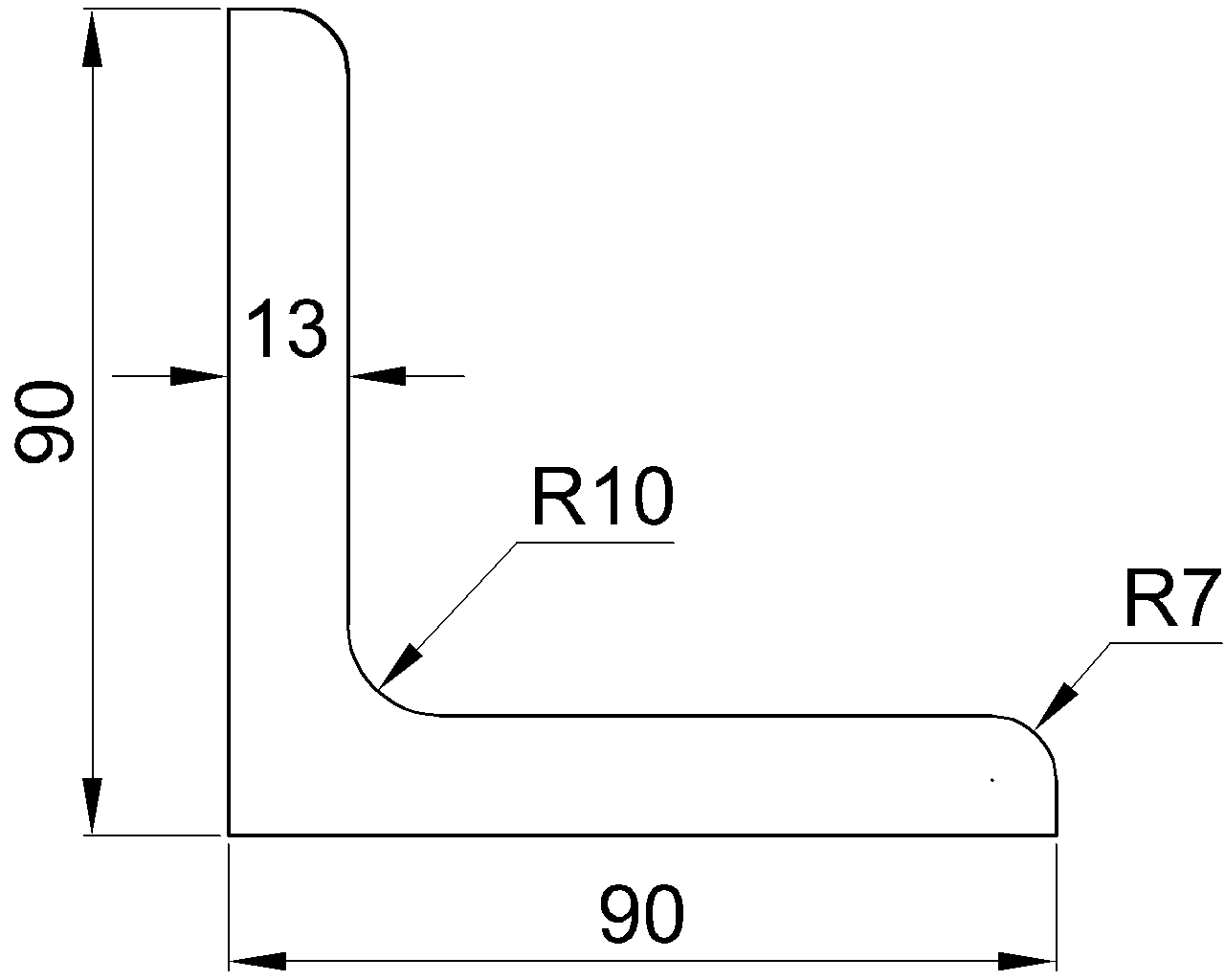
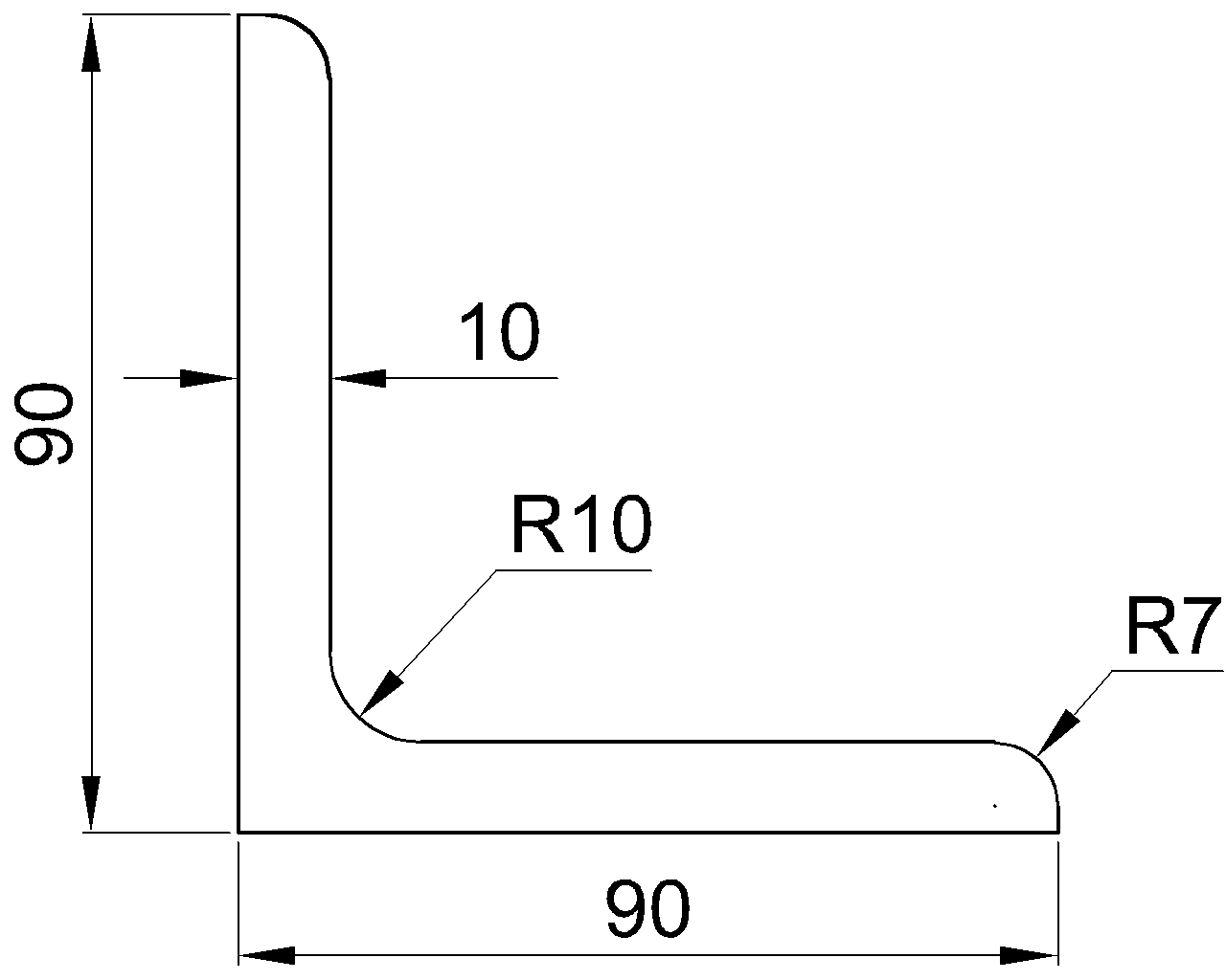
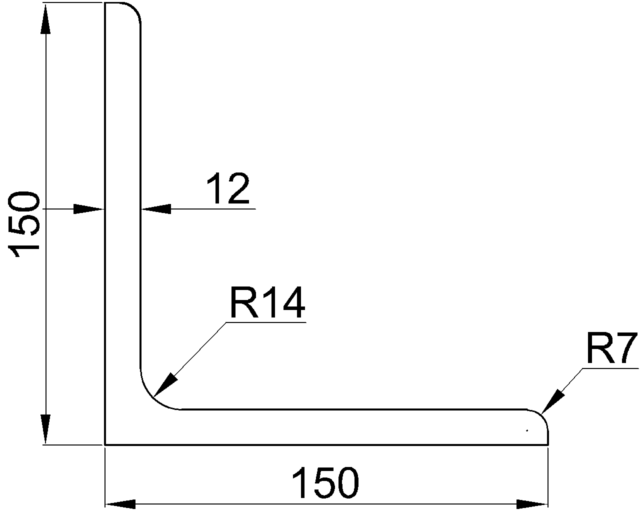
| Equal-leg angle | Constrained by its symmetry axis | Loading through a connected leg does not automatically pass through the shear center. |
| Unequal-leg angle | Generally not coincident and not constrained to a symmetry axis | Principal-axis orientation and shear-center location both deserve attention. |
| Built-up member | Depends on the complete assembled section | Spacing, connectors, symmetry, and whether components act together affect the appropriate model. |
These relationships describe idealized prismatic sections. Rolled fillets, corner radii, finite wall thickness, and the analytical method used can influence calculated coordinates. A diagram or trusted calculation should be consulted rather than estimating an exact shear-center position from a simplified outline.
Why channels are a useful example
A channel has one axis of symmetry, but its flanges extend to only one side of the web. Under transverse shear, the shear flow in those flanges creates a rotational effect. The external load must act through a point outside the web on the opposite side from the open portion of the channel to balance that effect without twisting.
This behavior can be surprising in framing details. A load applied near the channel centroid may look centered in an elevation, yet still be eccentric to the shear center. A shelf angle, deck edge, supported plate, or connection attached to the flange tips can increase the offset further.
Back-to-back channels may form a symmetric built-up section, potentially moving the shear center to a more intuitive location. That conclusion depends on the spacing and on whether the connectors provide the intended composite action. Two channels shown near each other should not automatically be treated as one fully acting section.
Why connection location matters
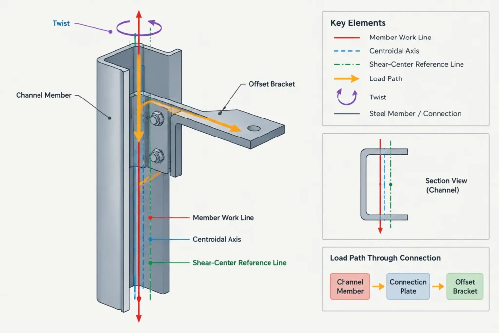
The relevant line of action is determined by how force enters the member, not merely by the member centerline shown in plan. A designer or detailer should identify the actual load-transfer path through bolts, welds, plates, seats, brackets, or supported framing.
Common sources of shear-center eccentricity include:
- Framing into only one leg of an angle.
- Attaching a bracket to the flange tips of a channel.
- Supporting a load from one side of a tee stem.
- Offsetting deck edges, façade supports, rails, or equipment from the member axis.
- Using a model insertion line that does not represent the connection work line.
- Changing a member orientation without moving the applied-load location.
A connection may also restrain twist. Such restraint does not erase the eccentricity; it changes how the resulting torsional action is resisted and transferred into adjacent components.
Shear center, torsional constant, and warping
Locating the shear center answers where a transverse load should act to avoid torsion from cross-sectional eccentricity. It does not by itself describe how strongly the member resists twisting.
The torsional constant is used in evaluating Saint-Venant torsional stiffness. Open sections such as channels and angles generally behave very differently in torsion from closed HSS. Warping properties and end restraints can also become important, particularly for open sections whose cross sections do not remain free to warp.
Accordingly, centroid location, shear-center location, torsional constant, and warping properties are related concepts, but they are not interchangeable table values.
A practical CAD and modeling workflow
1. Confirm the section orientation
Establish which way the web, flanges, legs, or stem face in the actual model. Mirroring a channel or angle also mirrors the shear-center location relative to the profile.
2. Keep reference points separate
Use distinct construction points or layers for the centroid, member work line, model insertion point, connection line, and shear center. Coincident points can share coordinates, but they should not be assumed to represent the same concept.
3. Draw the real load line
Trace the force through the supported element and connection components. In three-dimensional work, inspect the offset in both transverse directions rather than relying on one elevation.
4. Measure eccentricity perpendicular to the force
The torsional lever arm is the perpendicular distance between the force line and the shear center. A dimension to the centroid may be useful for other purposes, but it does not replace this measurement.
5. Review member and connection restraints
Check whether adjacent framing, diaphragms, bracing, plates, or supports restrain rotation or warping. Record these as analysis and coordination conditions rather than silently assuming full restraint.
6. Recheck substitutions and rotations
Replacing a W-shape with a channel, rotating a tee, or changing an angle orientation can alter the shear-center relationship even when overall depth remains similar. Load locations and connection geometry should be reviewed after every such change.
Common mistakes to avoid
- Using the bounding-box center: The middle of a CAD extents box is not necessarily the centroid or shear center.
- Assuming every section property is centroidal: A shape table may report centroidal properties without providing shear-center coordinates.
- Placing loads on the model insertion line by default: Software reference lines may be selected for convenience rather than structural meaning.
- Ignoring out-of-plane offsets: A connection that looks centered in one view can be eccentric in another.
- Treating two separate shapes as a single section: Built-up action depends on the connection between components.
- Assuming restraint eliminates torsion: Restraint redirects torsional effects into connections and surrounding framing.
Using the distinction effectively
The centroid answers where the cross-sectional area is centered and provides the origin for many familiar bending properties. The shear center answers where a transverse load must act to avoid twisting the section. They coincide for many doubly symmetric shapes, but they can be far apart for open sections such as channels and angles.
For practical steel work, the key step is to compare the actual connection load line with the shear center—not merely with the geometric center, web centerline, or CAD insertion point. Keeping those references explicit makes section-property data more useful and helps designers, drafters, and detailers recognize torsional effects before they become hidden in a model or connection detail.