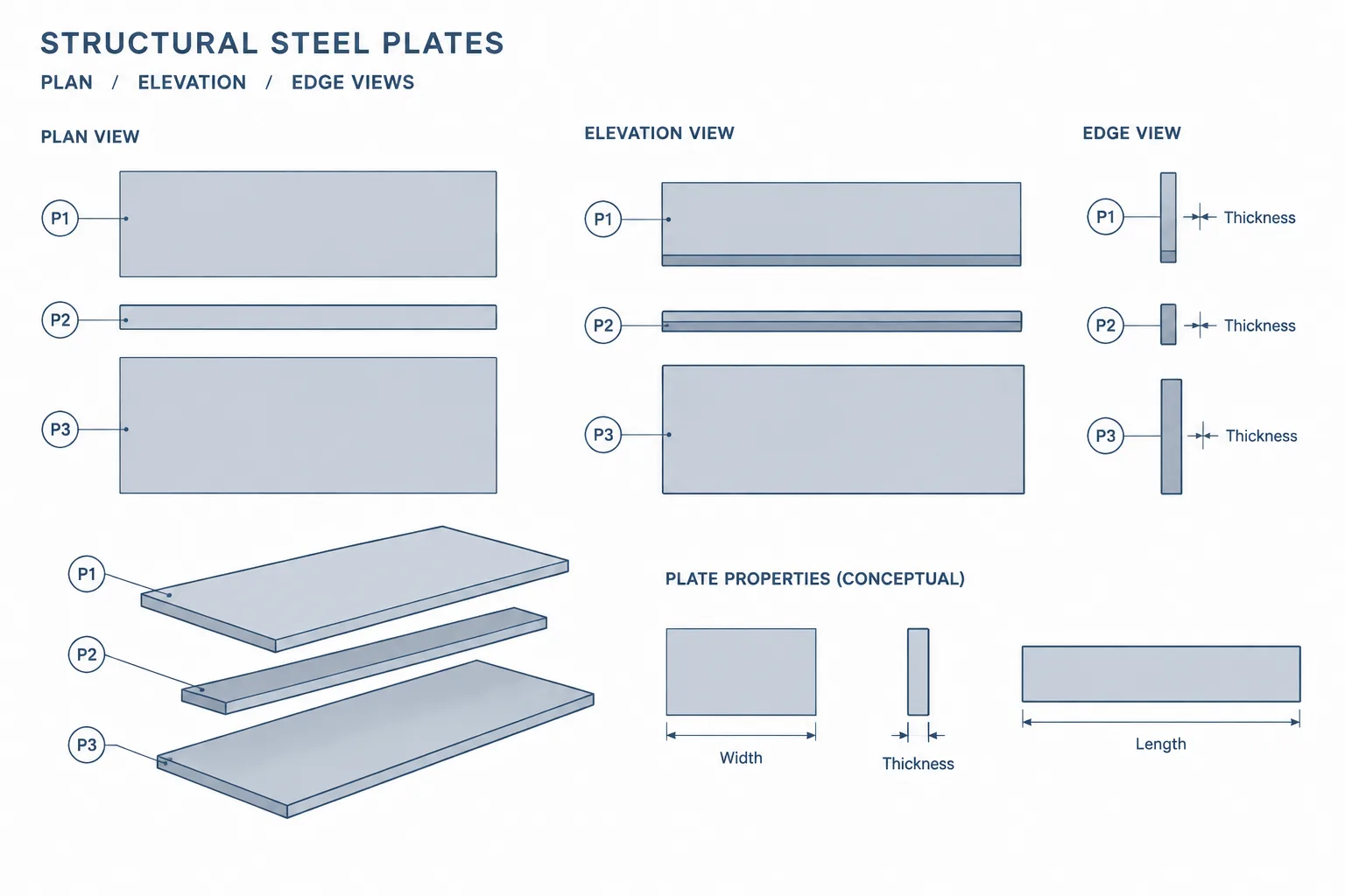
Structural steel plate callouts look simple, but a short label can carry several kinds of information: plate thickness, width, length, quantity, material, piece mark, and sometimes orientation. The challenge is that drawing conventions are not perfectly universal. A dimension sequence that is obvious in one fabrication shop may be ambiguous on another project.
Reliable interpretation therefore requires more than reading characters from left to right. Drafters, detailers, designers, and reviewers must connect the callout to the plate view, dimension lines, bill of materials, connection detail, and project-specific conventions.
What a plate callout is intended to communicate
A plate callout identifies a flat steel component and distinguishes it from rolled shapes such as W-shapes, channels, angles, tees, and HSS. A basic callout commonly begins with an abbreviation such as PL, followed by dimensions describing the plate.
In symbolic form, a rectangular plate might be identified as:
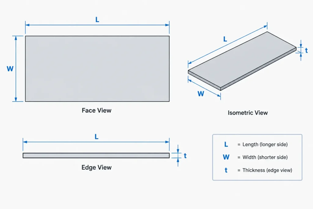
PL t × W × L
Here, t represents thickness, W represents width, and L represents length. This is a common and useful convention, but it should not be treated as automatic proof of dimension order. The drawing legend, shop standard, bill format, and dimensioned views remain controlling sources of information.
A complete plate description may also include:
- A piece or part mark
- The required quantity
- A material designation
- A finish, coating, or preparation note
- Hole or slot information
- Cut shape, bevel, bend, or contour references
- A connection or assembly association
Thickness, width, and length are different kinds of dimensions
Thickness
Thickness is the dimension through the plate. In a plan or elevation where the broad face is visible, thickness is usually out of the drawing plane and cannot be measured directly from that view. It must come from the callout, a section, a detail, or the material list.
Do not infer thickness from line spacing in a schematic detail. Structural drawings often use diagrammatic linework, and a plate may be exaggerated so it remains visible at the plotted scale.
Width
Width generally describes the shorter face dimension of a rectangular plate, but that description is only a drafting convenience. A long, narrow plate can be rotated in the assembly, and its width may appear vertical, horizontal, or perpendicular to a member axis depending on the view.
For connection plates, width may correspond to the direction across a beam flange, along a column face, or between free edges. The physical orientation must be established from the detail rather than from the word width alone.
Length
Length commonly refers to the longer face dimension or to the direction treated as longitudinal for fabrication. For a rectangular plate, this may be straightforward. For a skewed, tapered, clipped, or irregular plate, however, a single overall length does not fully define the part.
Plate length should not be confused with a member work-point distance or the clear distance between connected components. End clearances, setbacks, cuts, and fit-up conditions can make these values different.
Why dimension order must be verified
Many drawings use thickness first, followed by width and length. Other documents may abbreviate the description, omit one face dimension when it is controlled elsewhere, or arrange dimensions to match a shop’s material-ordering practice. Metric and imperial projects can also use different notation and separators.
Before creating or revising a plate, check the following sources together:
- The plate callout beside the detail
- Dimension lines shown on the plate view
- Sections that reveal thickness and orientation
- The bill of materials or advance material list
- General notes and abbreviation legends
- Similar plates carrying different piece marks
- The connection geometry and available clearances
If two sources disagree, the answer should not be selected by assumption. The discrepancy should be resolved through the project’s review or clarification process.
Reading the callout in context
| Callout element | What it usually describes | What to verify |
|---|---|---|
| PL | A plate component | Whether the item is flat, bent, rolled, or part of a built-up member |
| First dimension | Often plate thickness | Project dimension-order convention and section views |
| Face dimensions | Overall width and length | Orientation, trimming, skew, and finished geometry |
| Quantity | Number of identical pieces | Whether quantity is per assembly, per location, or total |
| Piece mark | Unique fabrication identifier | Mark consistency across details and material lists |
| Material note | Required plate material | Contract documents and purchasing information |
| Finish note | Surface treatment or coating | Limits, masked areas, and assembly requirements |
Rectangular dimensions do not define every plate
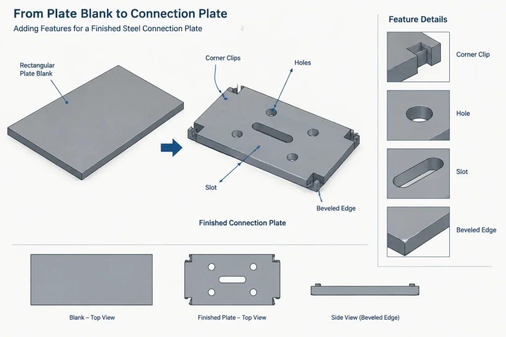
A thickness-width-length description can define the starting blank for a simple rectangular plate, but many connection plates require additional geometry. Examples include gusset plates, shear tabs, stiffeners, base plates, cap plates, splice plates, and plates fitted around rolled-shape fillets.
Additional information may be needed for:
- Clipped or chamfered corners
- Skewed or sloped edges
- Curved profiles and relief cuts
- Notches around flanges, webs, or welds
- Hole groups, slots, and access openings
- Beveled edges or weld preparation
- Bends and formed offsets
- Surface orientation or rolling-direction requirements when specified
A material-list size may describe the rectangular stock envelope rather than the final cut perimeter. Conversely, some systems list finished overall dimensions. The fabrication drawing should make that distinction clear.
Plate orientation in plans, elevations, and sections
Plate callouts normally identify size, not spatial orientation. Orientation comes from the views. A plate seen face-on appears as an area bounded by its cut edges. A plate seen edge-on may appear as two closely spaced lines or as a single symbolic line, depending on scale and drafting practice.
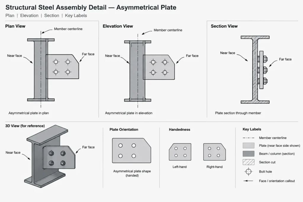
When checking orientation, identify:
- Which plate face contacts the supporting member
- Which edges are horizontal, vertical, sloped, or skewed
- Whether the plate is centered or offset from a member centerline
- Which side receives welds, bolts, or attached parts
- Whether the view is looking from the near side or far side
This is especially important for plates with nonsymmetrical hole patterns, unequal corner clips, one-sided bevels, or attachments on only one face. Mirroring such a plate can create a different part even when its overall dimensions remain unchanged.
Piece marks and quantities
The piece mark connects the graphical plate to fabrication and assembly records. Plates with identical overall dimensions do not necessarily deserve the same mark. Differences in holes, edge preparation, material, finish, orientation, or attached components can require separate identification.
Quantity must also be read carefully. A detail may show one plate but require matching plates on opposite sides of a web. Another callout may state a quantity per assembly while the material list reports the total number required. Review the assembly context before changing a quantity or consolidating marks.
A practical CAD and detailing workflow
- Establish the project convention. Review typical details, legends, and material-list headings before interpreting dimension order.
- Model or draw the finished plate. Include required cuts, holes, slots, and edge conditions rather than stopping at the rectangular stock outline.
- Choose a stable insertion reference. Use a meaningful corner, center, work point, or connection line so later revisions remain manageable.
- Coordinate all views. Confirm that plan, elevation, section, and detail views show the same handedness and edge geometry.
- Separate geometry from annotation. Do not rely on text alone to correct an inaccurately drawn plate.
- Cross-check the material list. Verify thickness, overall dimensions, material, quantity, and piece mark against the detailed part.
- Review interfaces. Check nearby flanges, fillets, welds, bolt access, erection clearance, and adjacent plates.
- Flag uncertainty. Ambiguous or conflicting information should be documented and resolved rather than silently interpreted.
Common plate-callout mistakes
- Assuming every office uses the same thickness-width-length order
- Swapping width and length because the plate is rotated in the view
- Treating a stock rectangle as the finished plate shape
- Ignoring handedness in an asymmetrical plate
- Reading a schematic line spacing as actual thickness
- Copying a piece mark to a plate with different holes or cuts
- Confusing assembly quantity with project quantity
- Failing to coordinate the callout with the material list
Use the callout as an index, not the whole definition
A structural steel plate callout is best understood as a compact identifier. It points the reader toward the plate’s basic size and classification, but the complete fabrication definition usually depends on several coordinated sources.
For dependable detailing, read the callout together with the visible geometry, dimensions, sections, connection information, piece marks, notes, and material records. That approach prevents dimension-order assumptions and helps ensure that the plate shown in CAD is the same plate intended for fabrication and assembly.