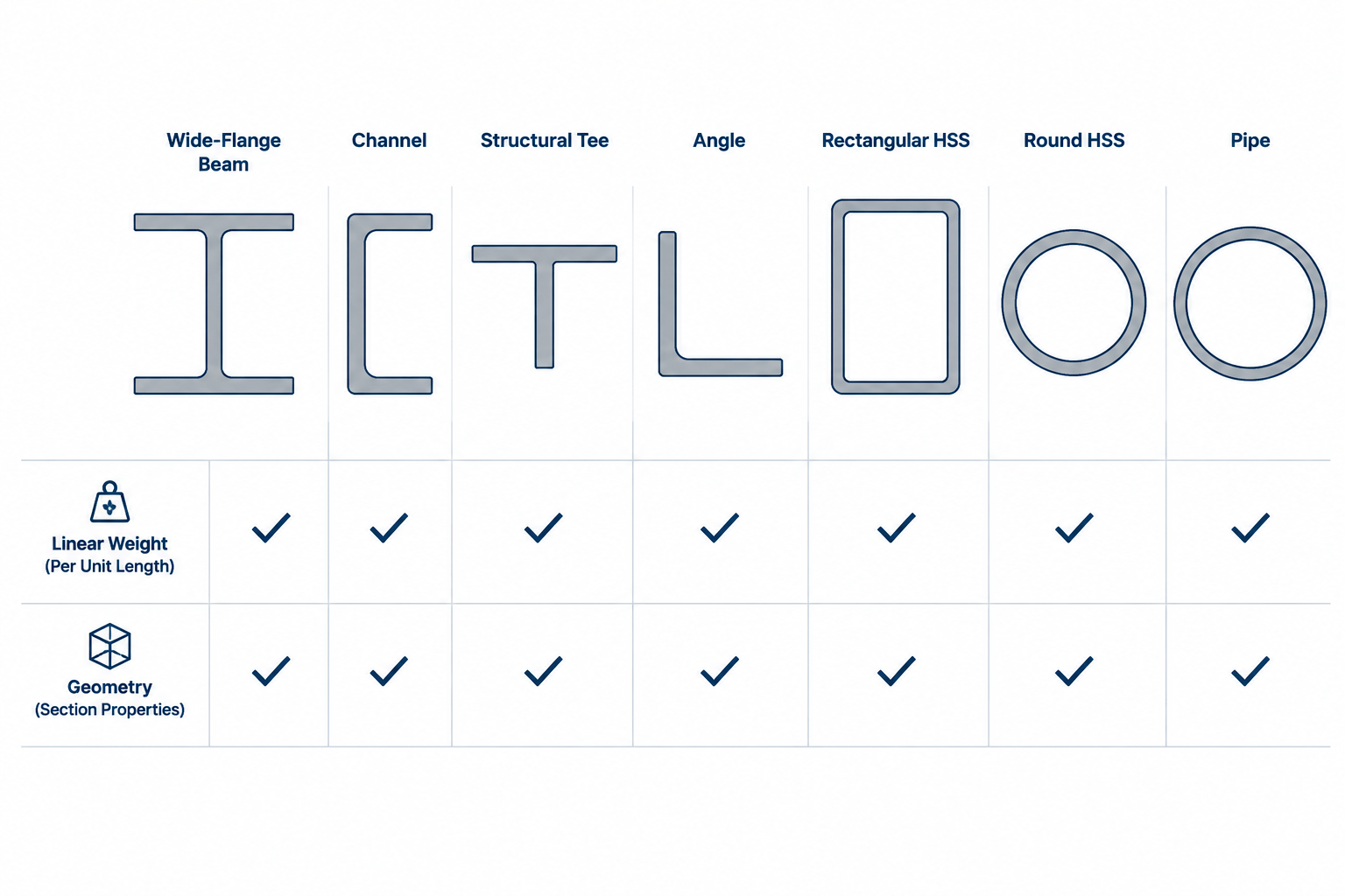
Structural steel designations compress important information into a short label, but they do not all follow the same pattern. In many rolled-shape names, the final number is the nominal weight per foot. In an angle, HSS, pipe, or plate designation, however, the numbers primarily describe geometry. Treating every designation as though it contains weight can produce incorrect material estimates, schedules, and CAD data.
This guide explains where weight per foot appears in common U.S. steel shape designations, where it must be obtained from a verified table, and how to use that information in drafting and estimating workflows.
What Does Weight per Foot Mean?
Weight per foot is the tabulated linear weight of a shape, commonly shown in pounds per foot for U.S. customary data. It provides a convenient way to estimate the weight of a member without calculating the cross-sectional area from individual dimensions.
The basic estimating relationship is:
Estimated bare member weight = tabulated weight per unit length × member length
For multiple identical pieces, multiply the result by the quantity. This gives the estimated weight of the base shape only. Connection plates, stiffeners, cap plates, base plates, bolts, weld metal, and other attached items must be handled separately when they are relevant to the estimate.
Although the word weight is commonly used in steel references and estimating, technical calculations may distinguish between mass and force. The important practical point is to keep the units consistent and to confirm whether a schedule, software field, or project document expects pounds per foot, kilograms per meter, total weight, or mass.
Shape Families That Commonly Include Weight in the Designation
W, S, M, and HP Shapes
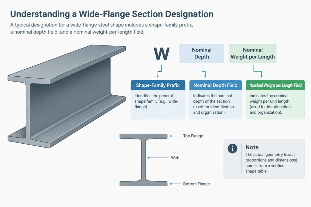
For common rolled beam and pile families, the designation generally consists of a shape-family prefix followed by a nominal depth and a nominal weight per foot. The prefix identifies the family:
- W identifies a wide-flange shape.
- S identifies an American Standard beam shape.
- M identifies a miscellaneous beam shape.
- HP identifies a bearing-pile shape.
The first number after the prefix represents nominal depth, not necessarily the exact overall depth. The number after the multiplication symbol represents nominal weight per foot in a U.S. customary designation. Exact depth, flange width, web thickness, flange thickness, and section properties must still be obtained from the applicable shape table.
This distinction matters in CAD. A drafter should not create an accurate section by treating the nominal depth in the name as the exact depth. The designation identifies the shape; the database or verified table supplies its actual geometry.
C and MC Channels
Standard channels and miscellaneous channels follow a similar naming pattern. The designation identifies the channel family, nominal depth, and nominal weight per foot. It does not fully describe flange slope, flange width, web thickness, toe geometry, or fillets.
Two channels with similar nominal depths may have different weights and substantially different detailing dimensions. The complete designation is therefore necessary in member marks, schedules, bills of material, and model properties.
WT, ST, and MT Structural Tees
Structural tees produced from rolled beam shapes are commonly designated by tee family, nominal tee depth, and nominal weight per foot. The tee depth is associated with the resulting split section rather than the full depth of its parent beam.
The tee designation alone should not be used to infer every dimension of the parent shape or the exact cut condition. For connection detailing, verify the actual stem thickness, flange dimensions, fillets, and other relevant geometry in a reliable tee table.
Shape Designations That Do Not State Weight per Foot
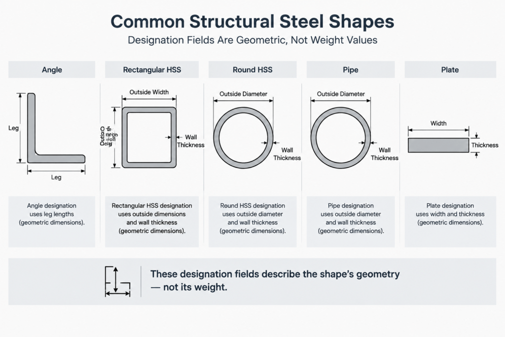
Other steel products use designation systems based mainly on dimensions. Their labels may contain several numbers, but none should be assumed to be weight per foot.
| Shape or product | What the designation generally describes | Is weight normally embedded? |
|---|---|---|
| W, S, M, HP | Shape family, nominal depth, and nominal weight per foot | Yes |
| C, MC | Channel family, nominal depth, and nominal weight per foot | Yes |
| WT, ST, MT | Tee family, nominal depth, and nominal weight per foot | Yes |
| Angles | Leg sizes and thickness | No |
| Rectangular or square HSS | Outside dimensions and nominal wall thickness | No |
| Round HSS | Outside diameter and nominal wall thickness | No |
| Pipe | Nominal pipe size and wall classification or schedule | No |
| Plate | Thickness, width, and often length | No |
Angles
An angle designation describes its two leg dimensions and thickness. In an unequal-leg angle, leg order can also matter for orientation and communication. The thickness value is not weight per foot. Obtain the linear weight from a verified angle table or calculate it from an appropriate published area when needed.
Hollow Structural Sections
Square and rectangular HSS designations identify outside dimensions and nominal wall thickness. Round HSS designations identify outside diameter and nominal wall thickness. These values define the nominal product geometry; they do not include linear weight.
Do not estimate HSS weight by modeling four sharp-cornered plates unless the task specifically calls for a rough approximation and its limitations are understood. HSS corner geometry and the relationship between nominal and design wall values can affect calculated area and weight. A verified HSS table is the better source for scheduling and estimating.
Pipe
Pipe naming uses nominal pipe size together with a wall designation such as a schedule. Nominal pipe size is not necessarily the measured outside diameter, and schedule is not weight per foot. Because different nominal sizes and schedules produce different wall thicknesses and weights, use a pipe table appropriate to the specified product.
Plate and Bar
Plate and bar callouts usually communicate dimensions rather than linear weight. Total weight depends on thickness, width, length, quantity, and material density. CAD and estimating systems may calculate weight from modeled volume, but the material assignment and units must be checked before relying on the result.
Nominal Weight Is Not the Same as Shipping Weight
The weight associated with a rolled-shape designation is a nominal or tabulated value. It is suitable for many preliminary takeoffs, comparisons, and member schedules, but it should not automatically be treated as the certified weight of a delivered piece.
Actual product dimensions and weight can vary within manufacturing tolerances. In addition, the delivered item may include features not represented by the base-shape weight, such as:
- connection plates and shear tabs;
- stiffeners, doublers, and bearing plates;
- end plates, cap plates, and base plates;
- shop-attached bolts or other hardware;
- galvanizing or other coatings;
- weld metal and deposited repair material;
- temporary fabrication or erection attachments.
For freight planning, lifting plans, crane selection, or other safety-critical work, use project-specific verified weights and procedures rather than a casual designation-based estimate.
A Practical Weight-Takeoff Workflow
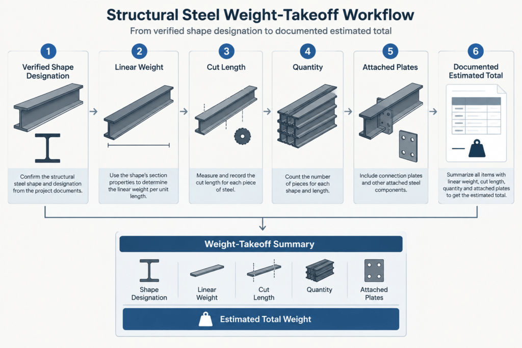
- Confirm the complete shape designation. Do not rely on nominal depth alone. Similar-depth shapes can have very different linear weights and properties.
- Identify the designation system. Determine whether the final value is weight per foot or a geometric dimension such as thickness.
- Obtain the cut length. Use the required project definition of member length. Grid distance, work-point distance, model length, and actual cut length may not be interchangeable.
- Use a verified linear weight. For W shapes, channels, and structural tees, the designation may already provide it. For angles, HSS, pipe, plate, and bar, consult the appropriate reference data.
- Keep units consistent. Do not multiply a metric linear mass by an imperial length or mix inches with feet without conversion.
- Apply quantity. Confirm whether the takeoff line represents one member, several identical pieces, or an assembly.
- Add attached material separately. Include plates, stiffeners, and other components at the level of accuracy required for the task.
- State the basis of the result. Label the result as nominal, estimated, modeled, calculated, or verified so downstream users understand its reliability.
CAD and BIM Data Checks
Steel models and CAD libraries often contain separate fields for shape name, length, area, material, linear weight, and calculated total weight. Those fields should be checked rather than assumed to agree automatically.
A useful quality-control review includes confirming that:
- the section profile matches the full designation;
- the model units match the section-property source;
- member length is measured using the intended endpoints;
- coping or trimming is handled consistently with the estimating method;
- attachments are not omitted or counted twice;
- custom or user-defined profiles have valid area and material data;
- reported totals distinguish individual members from assemblies.
A visually correct member can still produce an incorrect weight if its material density, profile area, length units, or quantity is wrong. Conversely, a schedule may contain the correct nominal linear weight while the drawn profile is only schematic. Geometry validation and data validation are related but separate tasks.
Key Takeaway
In several rolled-shape families—including W shapes, channels, HP shapes, and structural tees—the designation includes nominal weight per foot. In angles, HSS, pipe, plate, and bar, the numbers describe geometry or product classification instead. Recognizing that difference prevents common mistakes in steel schedules, CAD libraries, bills of material, and preliminary weight takeoffs.
Use the designation to identify the product, a verified shape table to obtain actual dimensions and properties, and project-specific information whenever total fabricated or delivered weight matters.


