Structural steel shape tables commonly list properties labeled rx and ry. These values are called radii of gyration. Although the name sounds like a physical radius, radius of gyration is a calculated section property that describes how the cross-sectional area is distributed around a specified centroidal axis.
For designers and technical users, radius of gyration is especially important when evaluating the slenderness of columns, braces, and other compression members. For drafters and modelers, understanding the property helps explain why member orientation, bracing, and unbraced length must be communicated clearly rather than inferred from a shape designation alone.
What Is Radius of Gyration?
The radius of gyration of an area is defined by the relationship:
r = √(I/A)
In this expression, I is the moment of inertia about the axis being considered, and A is the cross-sectional area. Because moment of inertia has units of length to the fourth power and area has units of length squared, radius of gyration has units of length.
The property can also be expressed as:
I = A r²
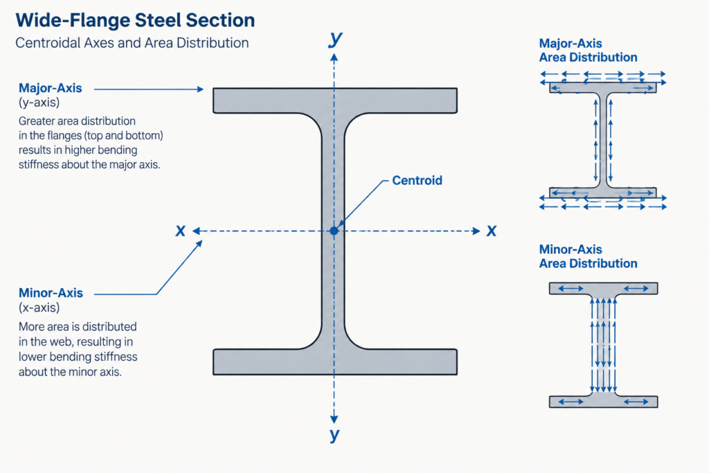
This relationship shows that radius of gyration summarizes the distribution of area around an axis. A larger value means that, in an overall mathematical sense, more of the section’s area is located farther from that axis. It does not identify a physical edge, fillet, bolt line, or measurable circular radius on the steel shape.
What Do rx and ry Mean?
Steel tables generally report separate radii of gyration for the section’s centroidal axes:
- rx is calculated from the moment of inertia about the x-axis: √(Ix/A).
- ry is calculated from the moment of inertia about the y-axis: √(Iy/A).
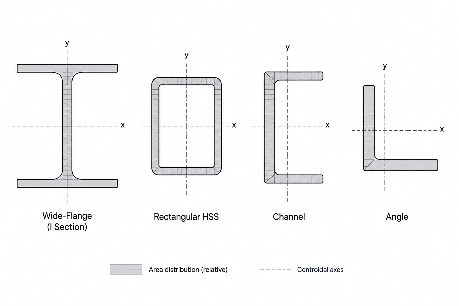
The corresponding axes must be confirmed from the table’s section diagram. For a W-shape shown with its web vertical, the x-axis normally passes through the centroid parallel to the flanges, while the y-axis passes through the centroid parallel to the web. Under that conventional orientation, rx is associated with the major-axis distribution and ry with the minor-axis distribution.
Axis labels should never be assigned from a plan or elevation view without checking the source convention. A member may be rotated in the model or installed with a different orientation, but its tabulated local section properties remain tied to the shape’s defined local axes.
How Radius of Gyration Relates to Column Slenderness
For a compression member, a commonly encountered geometric slenderness expression is:
KL/r
Here, L represents the relevant unbraced member length, K represents an effective-length factor used by the applicable design method, and r is the radius of gyration for the buckling direction under consideration.
The expression is dimensionless when consistent units are used. A smaller radius of gyration produces a larger slenderness ratio for the same effective length. This is why a W-shape may be much more sensitive to flexural buckling about its minor axis than about its major axis: its flange area is spread widely from the x-axis, while the cross section is comparatively narrow relative to the y-axis.
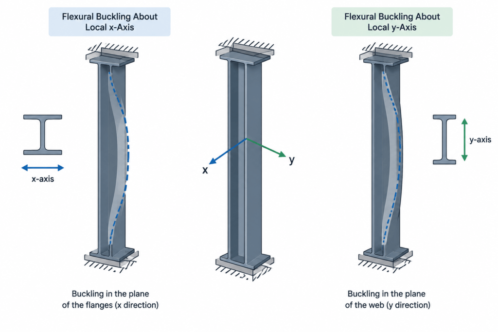
Both directions need to be considered. It is not sufficient to use the larger radius or to assume that the visually deeper direction automatically controls. Actual compression-member design also depends on end conditions, framing behavior, intermediate restraint, material properties, load effects, and the requirements of the governing design standard.
Effective length is not a drawing shortcut
The physical member length shown on a drawing is not automatically the effective buckling length. Restraint conditions and structural-system behavior determine how the appropriate length and effective-length treatment are established. A detailer should not derive K, KL, or a design capacity from connection appearance alone.
Drawings should instead identify member geometry, orientation, work points, connection locations, and required bracing information. Design assumptions belong in the engineering criteria or calculations and must be coordinated with the responsible engineer.
How Shape Type Affects rx and ry
| Shape type | Typical property pattern | Practical reading note |
|---|---|---|
| W and other doubly symmetric I-shapes | Major- and minor-axis radii can differ substantially. | Confirm which flange orientation corresponds to the modeled local axes. |
| Rectangular HSS | The two values depend on the outside orientation and wall distribution. | Do not swap depth and width without also swapping the associated axis properties. |
| Square HSS and round HSS | Symmetry can produce equal centroidal properties in equivalent directions. | Connections and local effects may still make the real framing behavior directional. |
| Channels | The centroid does not generally lie at the center of the overall width. | Use the published centroidal axes rather than a manually assumed web centerline. |
| Structural tees | The section is not symmetric about both centroidal axes. | Orientation and connection eccentricity require careful coordination. |
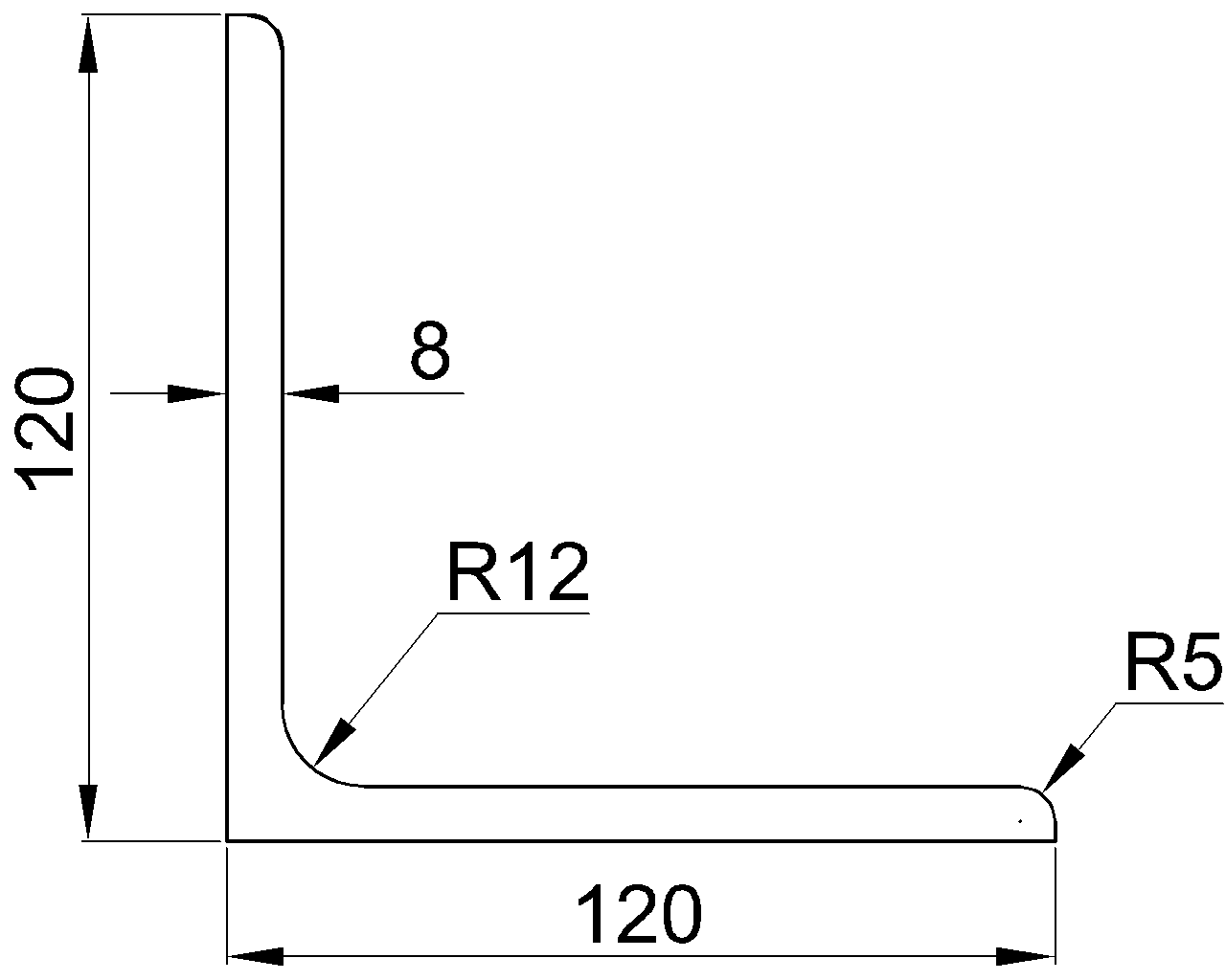
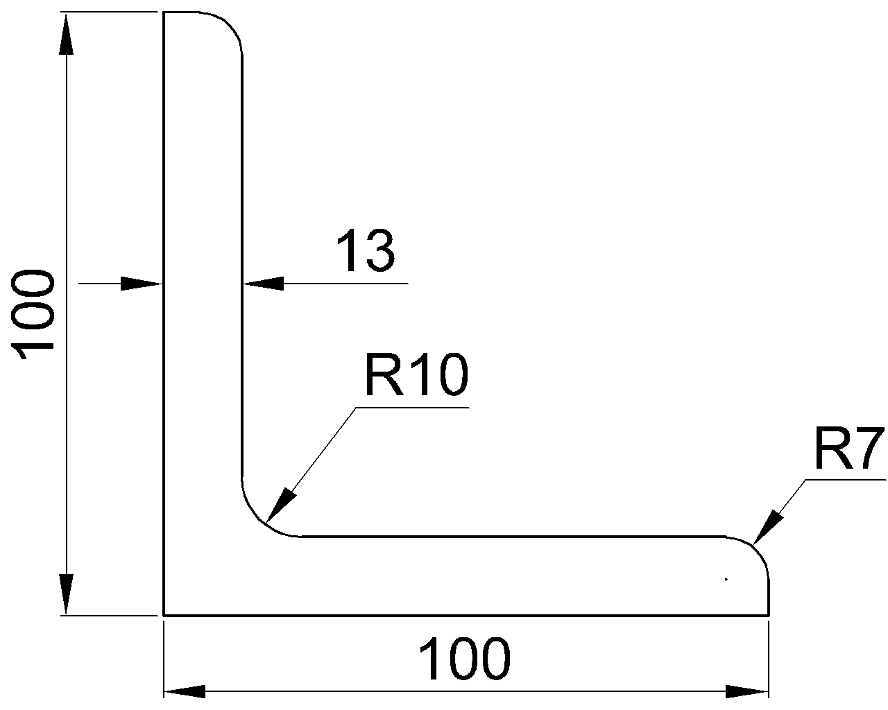
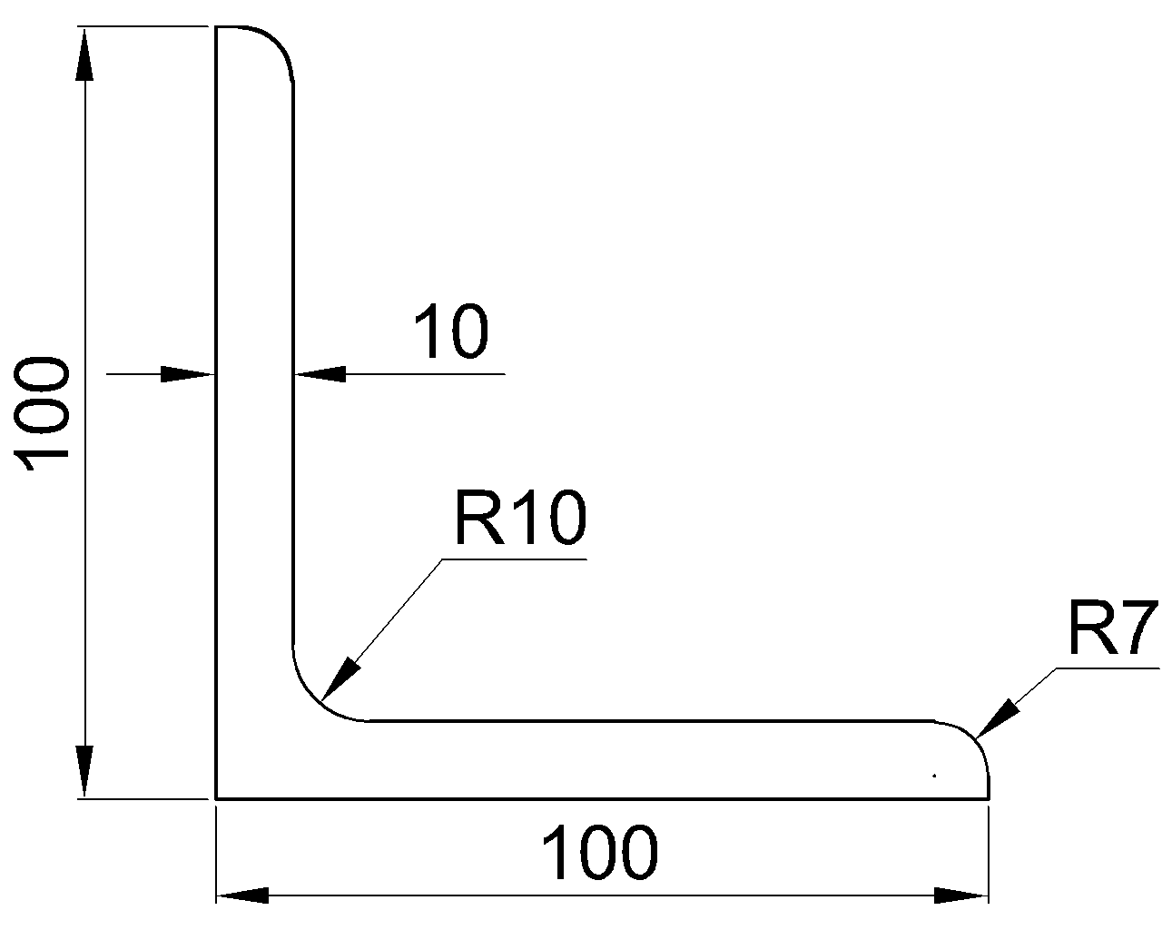
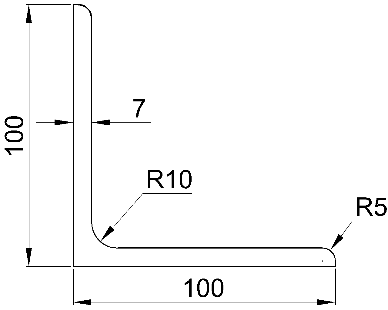
| Angles | Principal-axis properties may be needed in addition to geometric x- and y-axis properties. | Do not treat an angle like a small W-shape or assume its legs define the critical axes. |
| HP shapes | Flange and web proportions differ from many beam-oriented W-shapes. | Read the actual HP property row rather than estimating from nominal depth. |
Centroidal Axes Versus Principal Axes
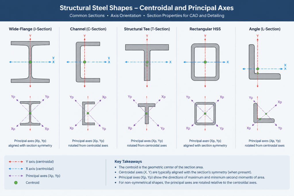
For doubly symmetric sections, the familiar centroidal x- and y-axes are also principal axes. Unsymmetric sections require more care. An angle, for example, may have tabulated properties about principal axes often identified with labels such as u and v. These axes pass through the centroid but are rotated relative to the legs or drawing axes.
Principal-axis behavior matters because flexural buckling is not always aligned with the obvious horizontal and vertical directions. Product of inertia and the relationship between geometric and principal axes can become relevant for unsymmetric shapes. Users should follow the axis sketch and definitions supplied with the selected shape-property reference rather than transferring assumptions from a symmetric I-shape.
Radius of Gyration Is Not a Standalone Capacity
A frequent mistake is to compare two members using only rx or ry and conclude that the member with the larger value has the greater compression capacity. Radius of gyration is useful for slenderness, but it is only one input.
Two shapes can have similar radii of gyration while having different areas, weights, proportions, torsional properties, local slenderness characteristics, or material specifications. Since axial force is carried by the full cross-sectional area and stability depends on multiple conditions, radius of gyration cannot replace a complete design check.
It should also not be confused with these related properties:
- Moment of inertia, I: measures area distribution about an axis and is used in stiffness and deflection relationships.
- Section modulus, S: relates moment of inertia to the distance from the neutral axis to an extreme fiber.
- Plastic section modulus, Z: describes the section’s fully plastic bending geometry.
- Torsional properties: describe resistance and response associated with twisting, which r alone does not capture.
- Nominal depth or width: physical envelope dimensions that do not directly state how all material is distributed.
A Practical Shape-Table Workflow
When using radius of gyration from a steel database or printed reference, apply a consistent checking process:
- Confirm the exact designation. Similar nominal depths do not imply interchangeable properties.
- Check the unit system. Keep section properties, member lengths, and calculation inputs consistent.
- Read the axis diagram. Verify the source’s local x- and y-axis orientation.
- Match the modeled orientation. Determine how the shape’s local axes correspond to the building grid and framing views.
- Select the correct radius. Use the property associated with the buckling direction being evaluated.
- Establish the relevant unbraced length. Do not automatically substitute overall member length.
- Verify restraint assumptions. Coordinate end conditions and intermediate bracing with the structural design information.
- Check other limit states. Do not use KL/r as the only acceptance test for a compression member.
CAD and BIM Coordination Tips
A three-dimensional steel model can make a member look fully restrained even when the analytical restraint has not been established. Contact between modeled objects, a symbolic connection, or a framing line crossing another member does not by itself prove effective bracing.
Use local-axis indicators where available, especially for rectangular HSS, channels, tees, and angles. In two-dimensional details, show the section orientation clearly enough that the web, flanges, legs, or HSS long side cannot be misread. If a member is intentionally rotated, avoid relying only on a generic shape label.
Finally, keep calculated properties separate from manually drawn geometry. Simplified CAD blocks may omit fillets, corner radii, or thickness conventions and should not be used to recalculate official section properties unless the geometry and method have been independently verified. Use a reliable shape-property source for rx, ry, area, and moments of inertia, then use CAD geometry for communication and coordination.
Key Takeaway
Radius of gyration is a compact measure of how a steel section’s area is distributed about a centroidal axis. Its main practical role is in member slenderness, where the correct r value must be paired with the corresponding buckling direction and an appropriately established effective length. Reading the axis convention, shape orientation, and restraint conditions correctly is more important than simply selecting the larger or smaller number from a table.