Structural steel shape tables provide consistent dimensions and section properties for design, estimating, and drafting. Those values are essential, but they do not mean every delivered member will match an ideal CAD profile at every point. Rolled and formed products are manufactured within permitted variations, while existing members may also be affected by coating, wear, deformation, or previous fabrication.
Understanding nominal vs. actual structural steel dimensions helps drafters and designers decide when a database value is appropriate and when a connection or field condition needs additional verification. The practical goal is not to model every manufacturing variation. It is to recognize which interfaces depend on actual geometry and provide suitable clearance, adjustment, or field measurement where needed.
What Is a Nominal Steel Dimension?
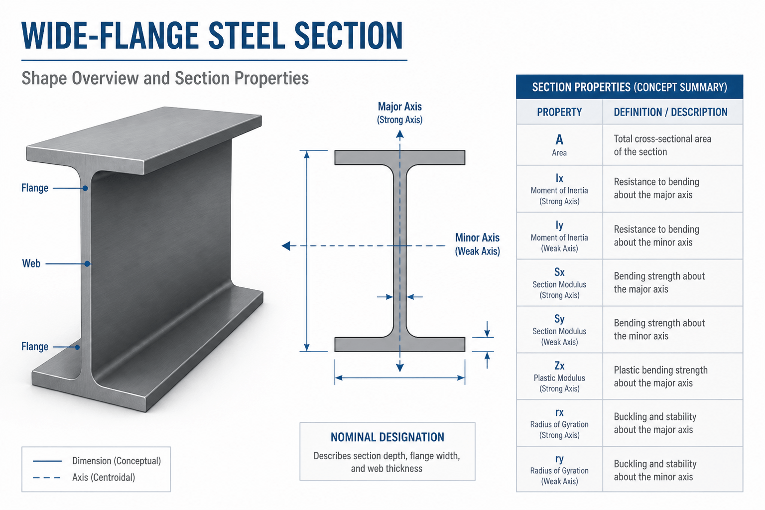
A nominal dimension is the published reference dimension used to identify and describe a structural shape. For a W-shape, common examples include overall depth, flange width, web thickness, and flange thickness. HSS tables commonly list outside dimensions and a design wall thickness. Channels, angles, tees, and HP shapes have their own defining dimensions.
These values support standardized communication. A designer, fabricator, and detailer can refer to the same shape designation without measuring an individual member. Published dimensions also form the basis for tabulated area, weight, moments of inertia, section moduli, radii of gyration, and other section properties.
Nominal does not mean approximate or optional. It means the value represents the standardized product rather than a guaranteed point-by-point measurement of a particular piece. The applicable product requirements and project documents govern acceptable manufacturing variation.
Why Actual Steel Geometry Can Differ
Structural shapes are produced through rolling, forming, welding, and finishing processes. These processes create controlled products, but physical production cannot reproduce an ideal mathematical profile without variation.
Depending on the product, relevant differences may include:
- Variation in overall depth, width, thickness, or length
- Flanges that are not perfectly square to the web
- Local sweep, camber, or twist
- Rolled fillets and tapered transition regions
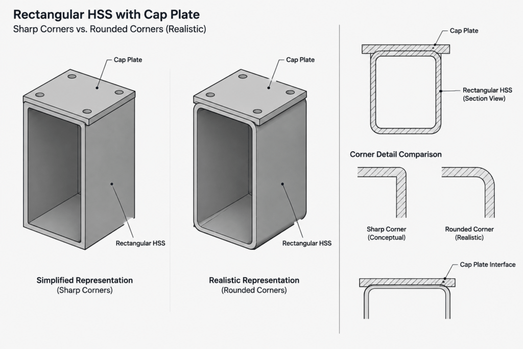
- Rounded HSS corners rather than sharp CAD corners
- Surface effects from coatings, galvanizing, scale, or corrosion
- Distortion introduced by cutting, welding, heating, or handling
The acceptable limits are not universal for every shape and condition. They depend on the product specification, fabrication requirements, and project criteria. When a variation could affect fit-up or performance, consult the governing documents instead of assuming a generic tolerance.
How Shape Type Affects the Difference
W-Shapes, HP Shapes, Channels, and Structural Tees
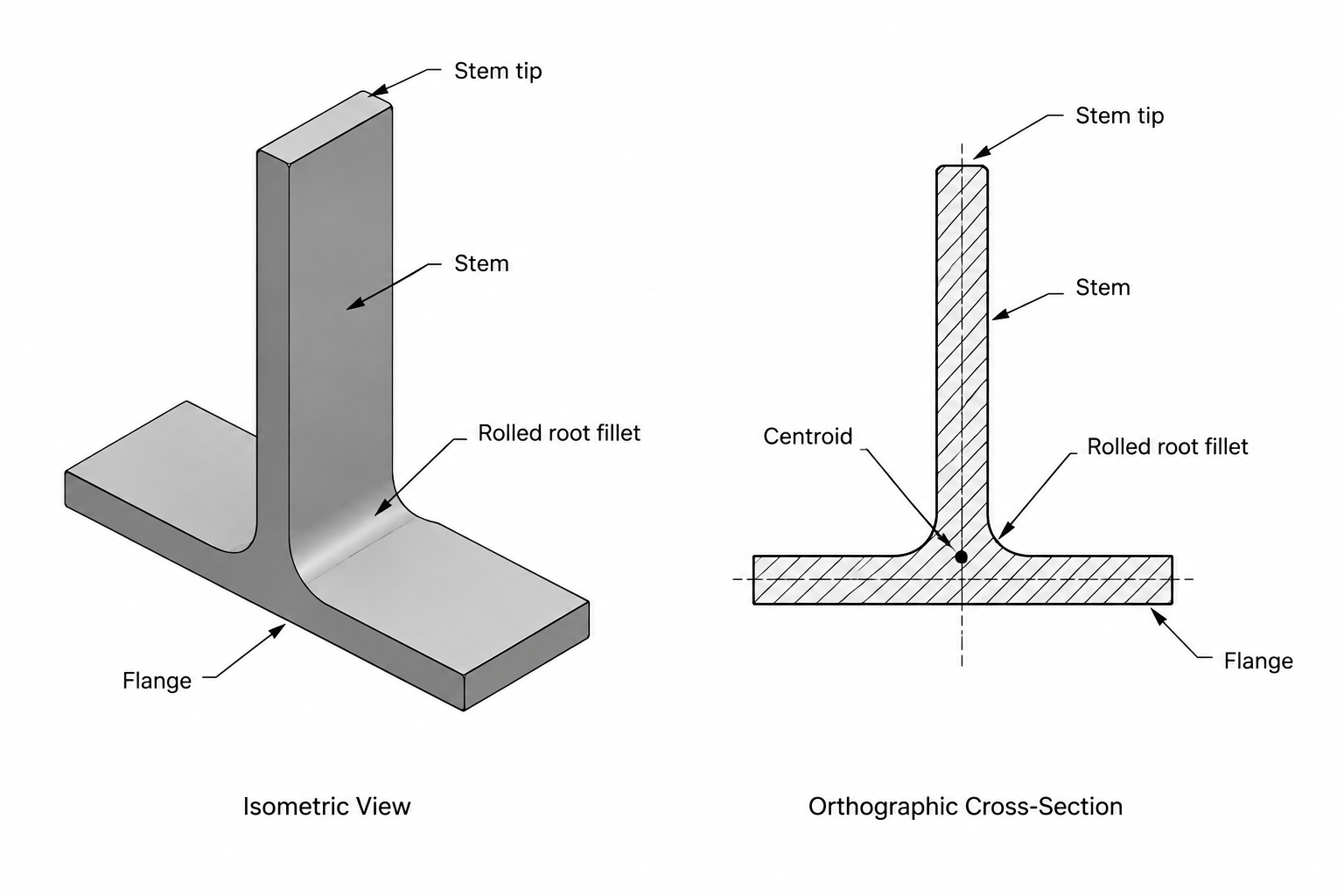
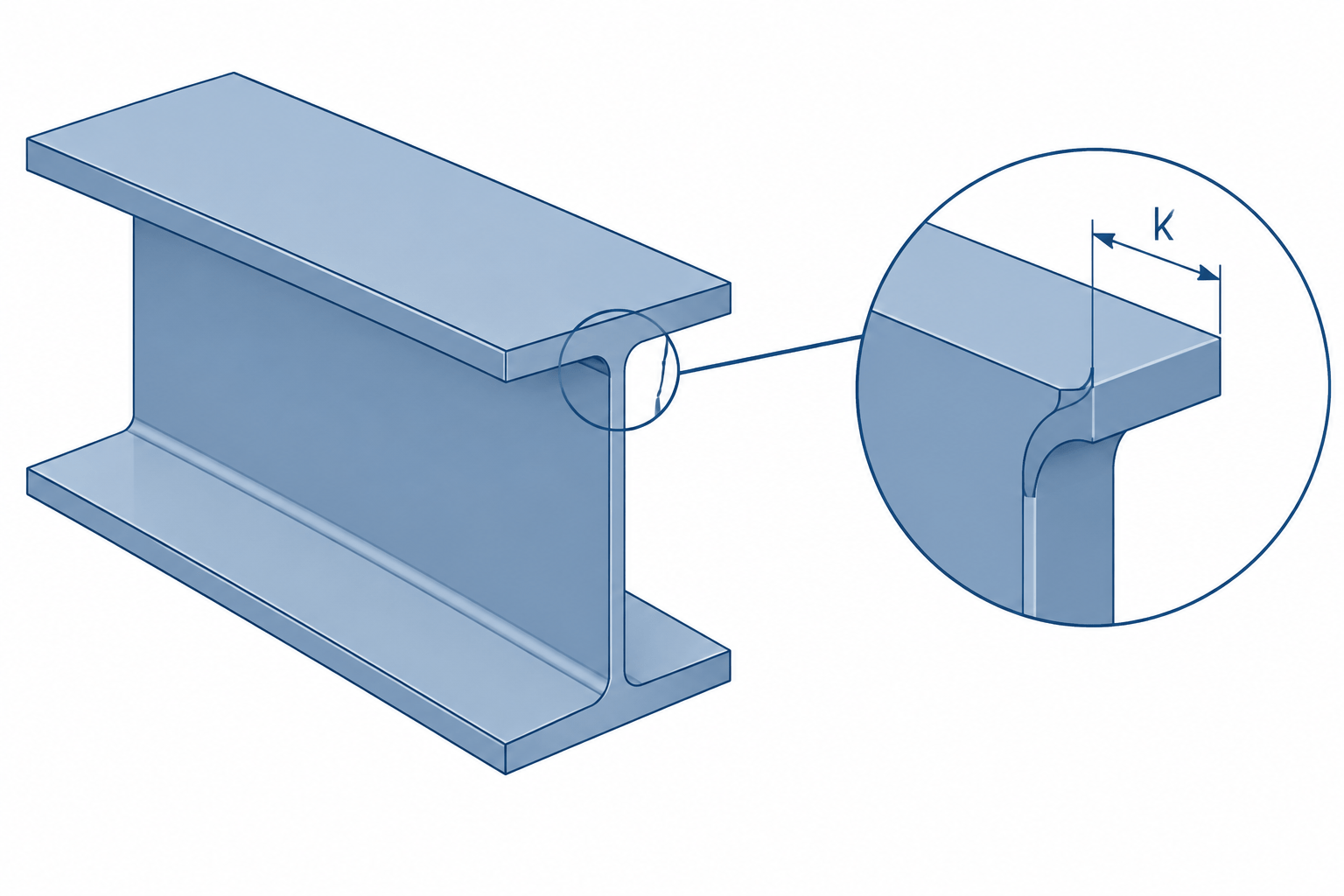
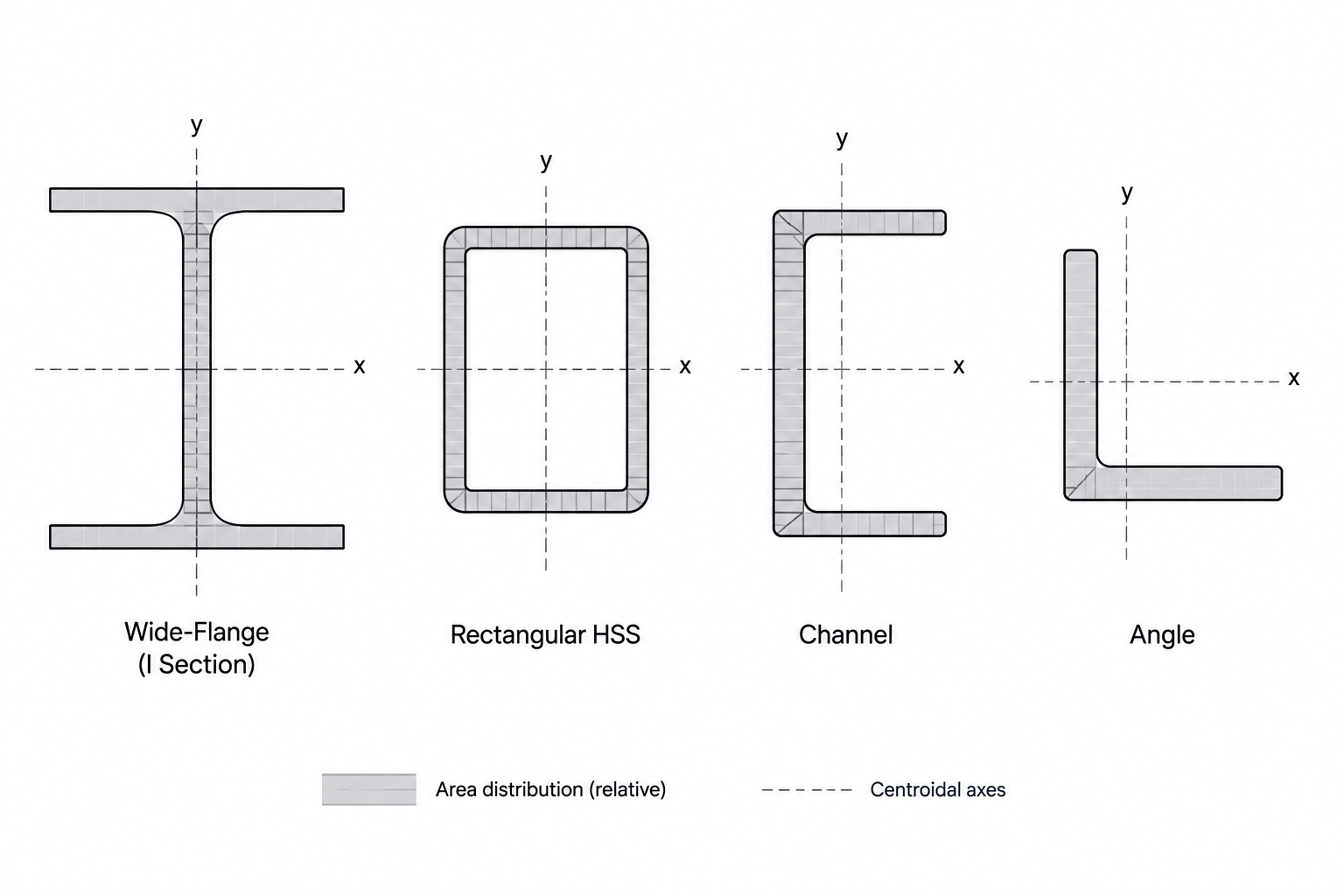
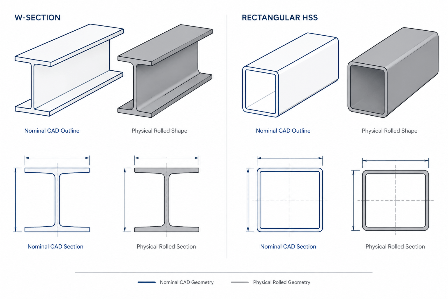
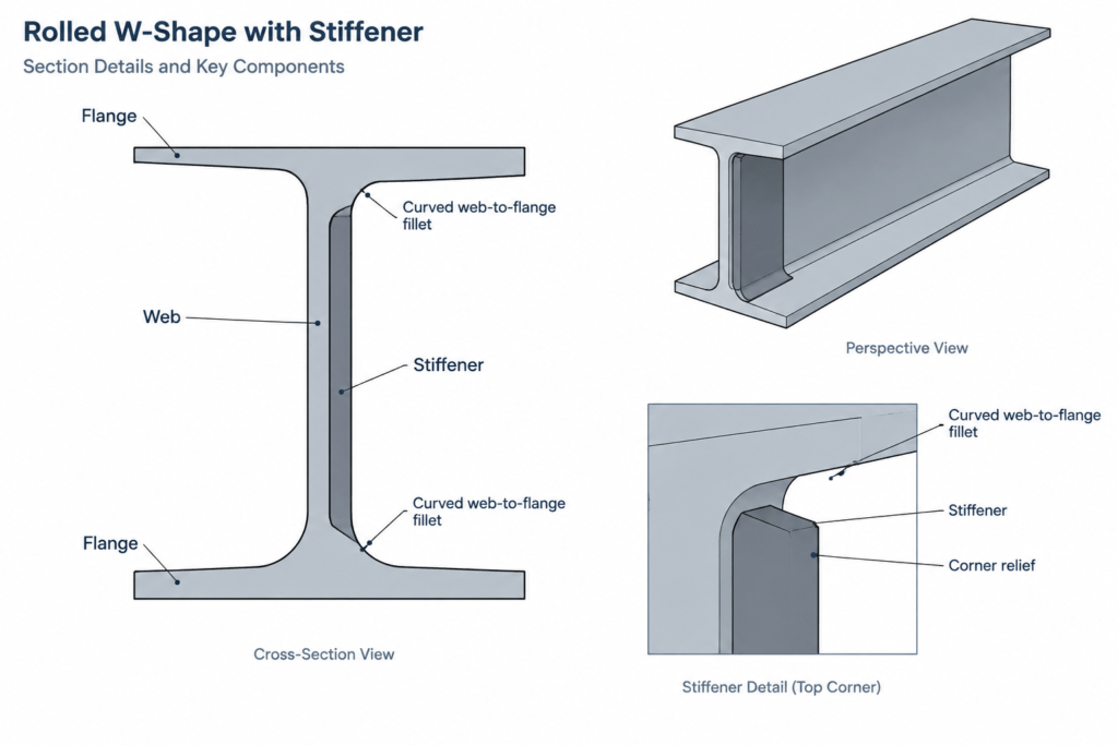
Rolled open sections contain curved transitions where webs and flanges meet. A simplified CAD block may show a sharp internal corner, but the physical member has a fillet or root region. The flange surfaces may also reflect the geometry of the rolling process rather than forming perfectly rectangular plates.
This matters when another component approaches the web-to-flange junction. A stiffener, clip angle, shear tab, washer, weld access feature, or fitted plate can conflict with the rolled transition even when a simplified elevation appears clear. Published detailing dimensions associated with the fillet region can help identify where flat contact should not be assumed.
A structural tee produced by splitting a wider rolled shape retains part of the original rolled profile. Its stem and flange should therefore be treated as rolled geometry, not as two ideal plates joined at a sharp corner.
Angles
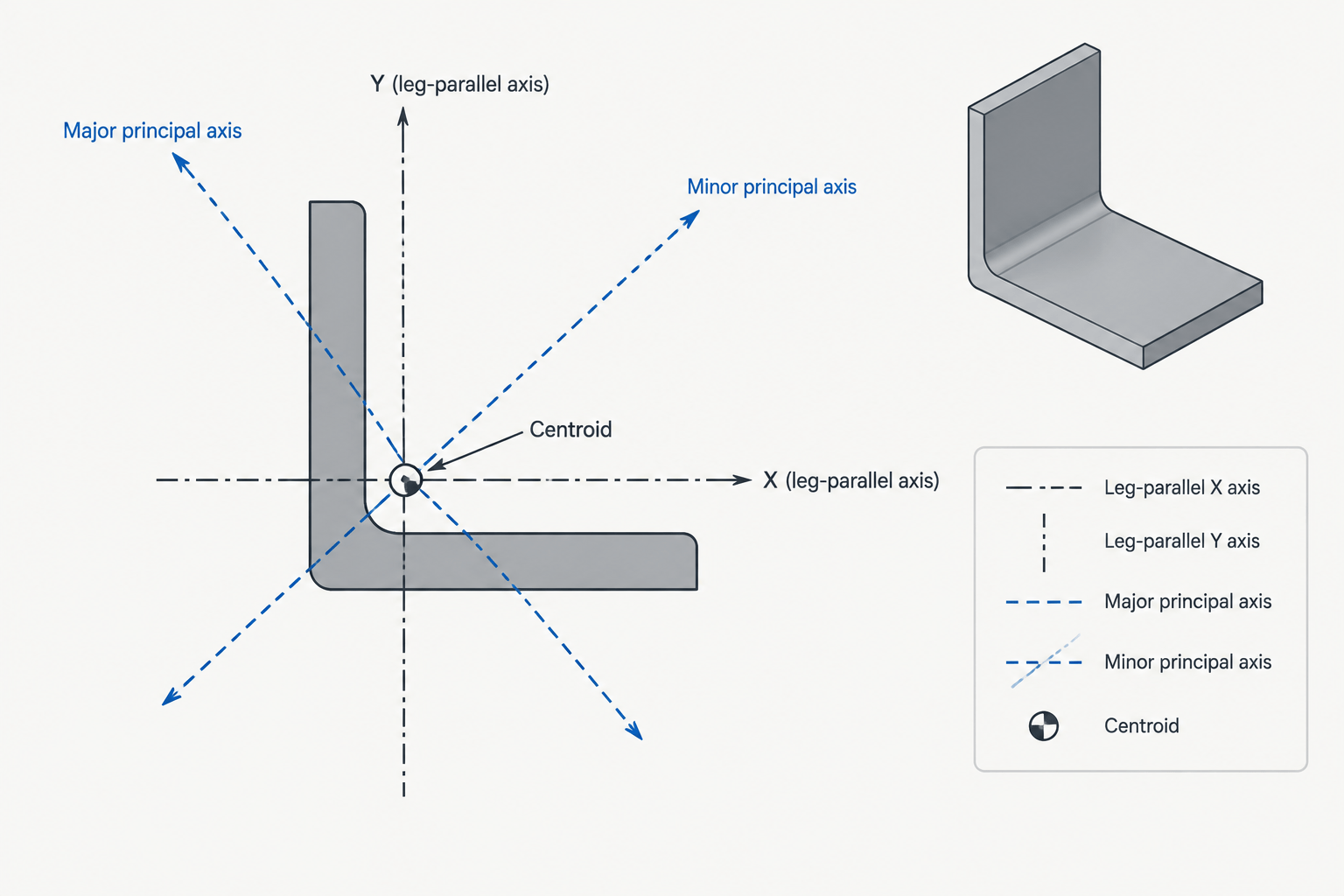
Structural angles have an inside heel radius and rounded toe regions. Their legs are not simply sharp-edged rectangles. This becomes important when an angle is placed tightly against another component, when bolts are located near the heel, or when a plate must fit between the heel and an adjacent surface.
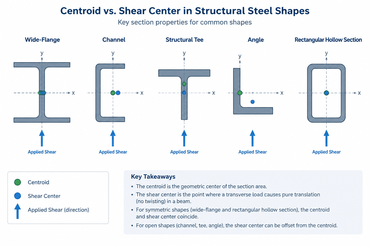
The centroid of an unequal-leg angle is also offset from both leg centerlines. A CAD insertion point chosen for graphic convenience should not automatically be treated as the centroid, shear center, or work point.
Hollow Structural Sections
Rectangular and square HSS have rounded corners. Their external corner profile and internal material distribution cannot be represented accurately by drawing two sharp-cornered rectangles. The relationship among outside dimensions, wall thickness, corner geometry, and section properties is handled by recognized shape data rather than by a crude CAD outline.
A simplified HSS block may be sufficient for a framing plan. It is less reliable for checking a fitted cap plate, through-plate, internal diaphragm, slot, or tightly wrapped connection. The actual corner region and fabrication method can affect detailing.
Round HSS and pipe-like products avoid corner issues, but their outside diameter, wall, ovality, and straightness still need appropriate consideration where fit is sensitive.
Nominal Dimensions in Common CAD Views
| Drawing or model use | Typical geometric approach | Main caution |
|---|---|---|
| Framing plan | Nominal centerlines and simplified outlines | Do not infer connection clearance from a small-scale view |
| Building section | Nominal depth and orientation | Allow for elevations, cambers, and interfaces defined elsewhere |
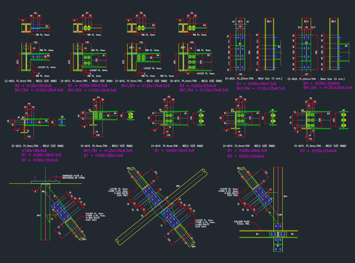
| Connection detail | Nominal profile with relevant fillets or corners | Check fitted parts and tool access |
| Fabrication model | Verified shape library and project detailing rules | A visually detailed profile is not proof of dimensional accuracy |
| Existing-condition drawing | Field-verified critical geometry | Database dimensions cannot confirm the installed condition |
Model precision should match the purpose of the deliverable. Adding excessive profile detail to every member can increase file size and visual clutter without improving decisions. Conversely, a centerline-only model is inadequate when a plate must fit around a rolled fillet or between existing surfaces.
Where Small Differences Become Important
Most general arrangement drawings can rely on nominal shape data. Greater care is warranted at interfaces where clearance or alignment controls fabrication and erection.
- Fitted stiffeners: Corners may need shaping or clipping to avoid a rolled fillet.
- End plates and cap plates: Edge alignment based on nominal width may not represent every delivered member.
- Bolted connections: Hole layout should follow the engineered connection and detailing requirements, not an unverified measured edge.
- Column splices: Differences in connected profiles can influence plate fit, alignment, and erection strategy.
- Base plates: Column placement, weld access, grout space, anchor-rod conditions, and erection adjustment should be coordinated.
- HSS connections: Rounded corners can affect plate contact, weld termination, and the geometry of cutouts.
- Renovation work: Existing members may differ from current database profiles or may have changed through service and modification.
Do Not Scale a Shape from a PDF or Screen Image
A drawing displayed at a particular scale is not a dimensional authority unless the document explicitly establishes that use. PDF conversion, printing, scanning, viewport settings, and image resizing can all change apparent geometry. Even a correctly scaled outline usually represents nominal rather than measured dimensions.
Use identified dimensions and verified shape data for drafting. For existing construction, use field measurements or survey information appropriate to the task. A raster image, photograph, or screen capture can provide context, but it should not silently become the basis for a close-fitting fabricated part.
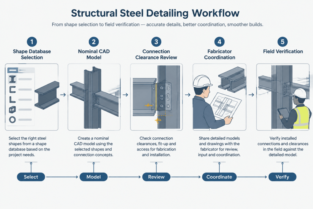
A Practical Detailing Workflow
- Confirm the designation. Verify the shape series and complete member designation before selecting a CAD profile.
- Use a reliable reference. Obtain dimensions and properties from an appropriate shape database or governing reference rather than tracing an image.
- Choose the required model detail. Use simplified geometry for layout and more representative fillets or HSS corners where fit depends on them.
- Identify critical interfaces. Flag fitted plates, close edge distances, enclosed conditions, adjacent finishes, and tool-access zones.
- Check the governing requirements. Review project specifications, fabrication criteria, and applicable product provisions for relevant tolerances.
- Coordinate with the fabricator. Ask how the shop prefers to handle clips, clearances, weld access, and member variation.
- Require verification where necessary. Use field dimensions, hold points, adjustable details, or templates when nominal data cannot establish the actual condition.
- Document assumptions. Make clear whether a dimension is nominal, detailed, surveyed, or to be verified.
Nominal Weight and Actual Piece Weight
The weight included in a steel designation or shape table is a standardized unit weight used for calculations and identification. It should not be interpreted as the exact scale weight of every individual member. Manufacturing variation, actual cut length, attached material, coatings, and fabrication features can affect delivered piece weight.
For structural analysis and preliminary quantity work, recognized tabulated values are normally the useful starting point. Shipping, lifting, billing, or equipment planning may require information tied to the fabricated assembly rather than the bare nominal section alone.
Better CAD Detail Without False Precision
A technically useful steel drawing communicates intent, interfaces, and verification requirements. It does not imply that a perfectly smooth CAD profile guarantees perfect field fit. Use nominal geometry confidently for its intended role, but distinguish it from surveyed dimensions and fabrication-specific information.
The most effective approach is selective precision: represent the steel shape accurately enough for the decision being made, include rolled or formed features where they affect connections, and avoid relying on database geometry for unknown existing conditions. That balance keeps drawings readable while reducing preventable clashes in the shop and field.