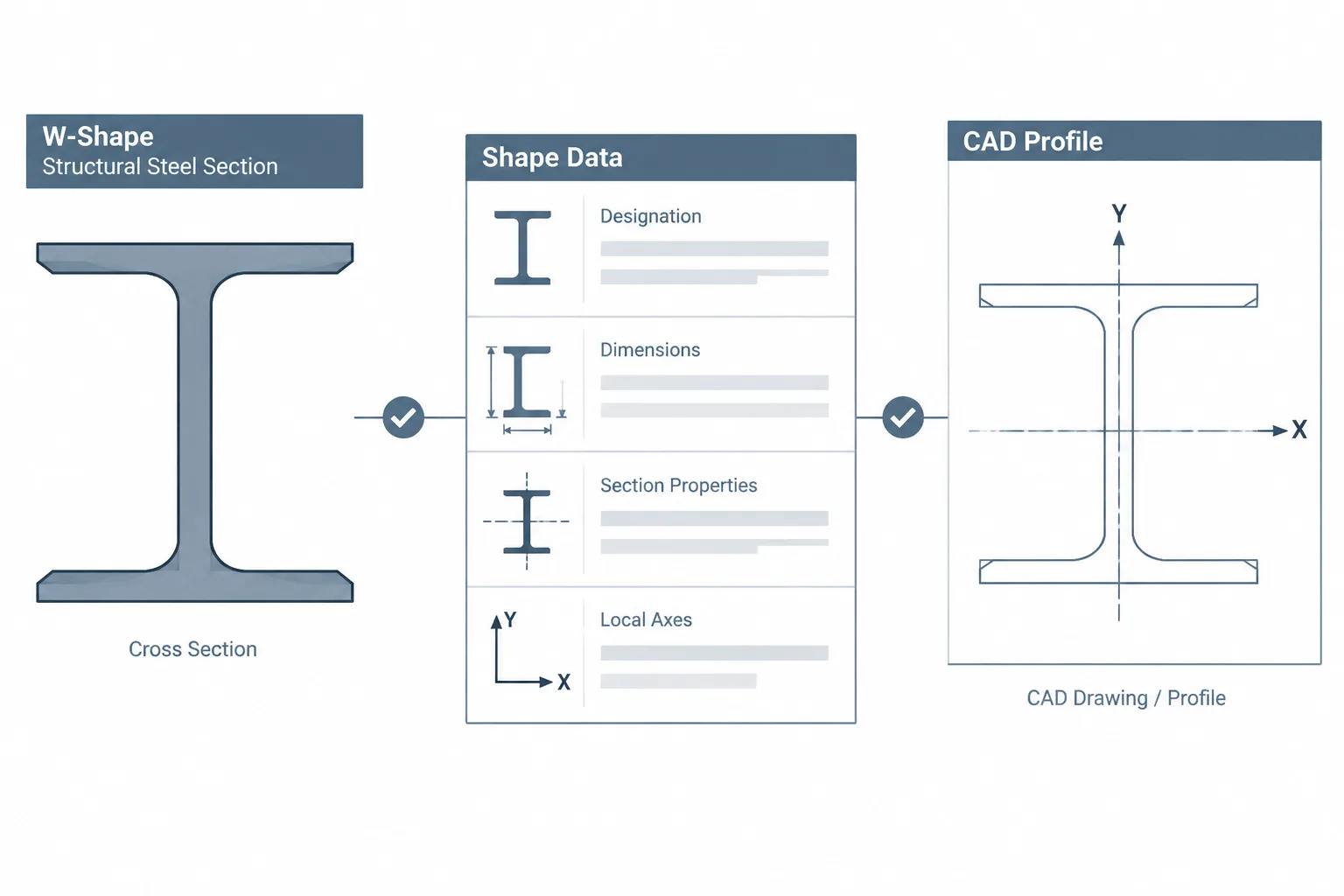
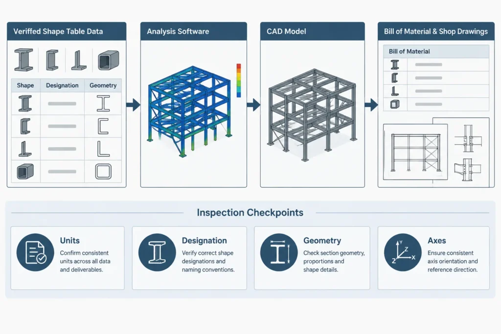
Structural steel shape data often moves through several tools before it reaches a finished drawing or calculation. A designation may be selected from a shape table, entered into analysis software, represented by a CAD block, copied into a bill of material, and finally shown on shop or erection drawings. Each transfer creates an opportunity for a wrong row, mixed unit system, outdated library, or simplified profile to pass unnoticed.
Verification does not mean independently recreating every published property. It means applying a repeatable set of checks that confirms the selected shape, its dimensions, its properties, and its graphical representation all refer to the same section. The following workflow is useful for W-shapes, channels, angles, structural tees, HP shapes, HSS, and other commonly tabulated steel products.
Start with the complete shape designation
The designation is the primary identifier, not a casual description. A nominal depth by itself is not enough because many rolled shapes share the same nominal series while having different weights, flange widths, thicknesses, and section properties.
Record the designation exactly as supplied by the project documents or verified reference. Check:
- The shape family, such as W, S, HP, C, MC, L, WT, or HSS.
- Every designation component, including nominal size and weight where applicable.
- Whether an angle has equal or unequal legs.
- Whether an HSS is round, square, or rectangular.
- Whether a tee is a rolled product or a split section identified from a parent shape.
- Whether the project uses customary or metric designations.
A familiar-looking designation should not be treated as proof that two records are equivalent. Similar names can belong to different shape families, and imported software libraries may use naming conventions that differ from the project documents.
Identify the source and unit system
Before comparing values, establish where each dataset came from. The shape-table record, engineering model, CAD block, and fabrication database may not share a common source. Even when the shape designation agrees, differences can appear because one system uses simplified geometry, converted values, or a different product catalog.
Confirm units for every field
Do not infer units from the magnitude of a value. Label them explicitly. Linear dimensions, cross-sectional area, weight per unit length, moments of inertia, section moduli, radii of gyration, and torsional properties all use different dimensional powers.
A practical worksheet should keep each property together with its unit. This is especially important when values are exported to spreadsheets or scripts, where a column heading may be separated from the original table notes.
| Data category | Typical verification question |
|---|---|
| Linear dimensions | Are depth, width, thickness, and radius-related values in the expected length unit? |
| Area | Was area converted as a squared unit rather than as a simple length? |
| Moment of inertia | Was the fourth-power unit handled correctly? |
| Section modulus | Was the cubic unit handled correctly? |
| Weight or mass | Is the field weight per length, mass per length, or total member quantity? |
| Torsional properties | Do the property definition and units match the intended calculation? |
One of the strongest warning signs is a file that mixes converted dimensions with unconverted section properties. A profile may look correct on screen while its analytical properties remain in another unit system.
Perform a dimensional identity check
Compare enough dimensions to establish that the records represent the same shape. Checking only overall depth is weak because several sections can have similar depths.
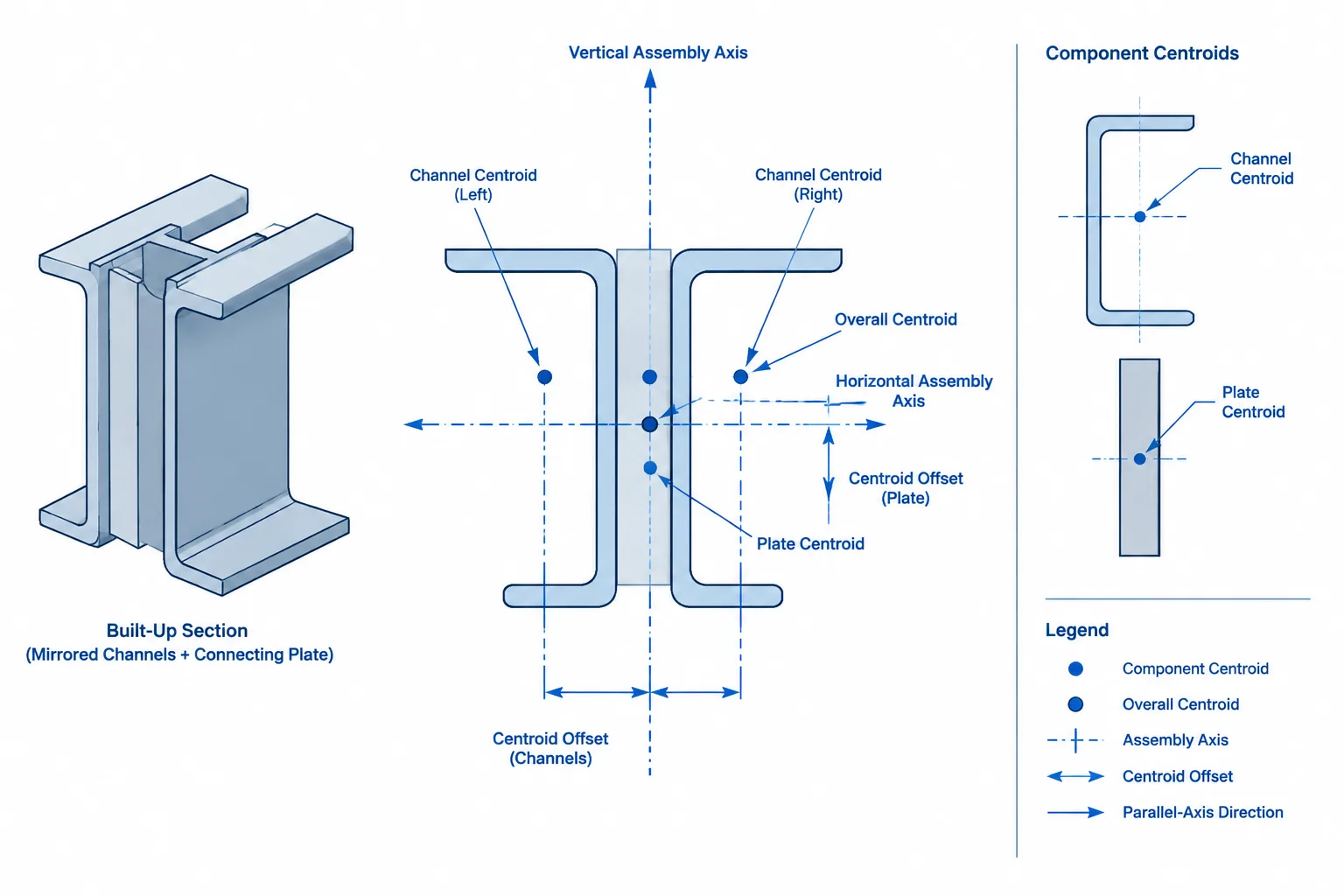
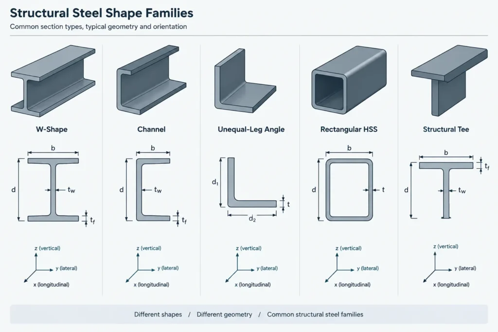
For an I-shaped rolled section, a useful identity check may include overall depth, flange width, web thickness, and flange thickness. For a channel, include the flange width and recognize that the centroid does not generally lie at the web back. For an angle, verify both leg lengths and thickness. For rectangular HSS, verify both outside dimensions and wall designation while keeping the orientation clear.
The objective is not to set arbitrary acceptance tolerances. It is to catch obvious mismatches such as:
- A neighboring row selected from a table.
- A light and heavy section from the same nominal depth series being confused.
- An unequal-leg angle with its legs reversed.
- A rectangular HSS rotated without updating local-axis references.
- A structural tee associated with the wrong parent shape.
- A channel mirrored or inserted from the wrong face datum.
Use relationships between properties as cross-checks
Section properties are not independent labels. Several have geometric relationships that can expose transcription or axis errors. These checks should use consistent units and the definitions applicable to the listed shape.
Area, weight, and member quantity
Cross-sectional area and nominal weight per unit length are related through material density and unit conversion. This makes area a useful reasonableness check for a weight entry. It does not justify replacing verified tabulated values with an improvised calculation, but it can reveal a misplaced decimal, incorrect unit, or copied value from another row.
Keep weight per unit length separate from total piece weight. Total weight depends on the length used, and the ordered length, cut length, and work-point length may not be identical.
Moment of inertia, section modulus, and extreme-fiber distance
Elastic section modulus relates moment of inertia to the distance from the relevant neutral axis to the extreme fiber. For a section symmetric about the checked axis, the relationship provides a straightforward consistency test. For an unsymmetric section, the positive-side and negative-side extreme-fiber distances may differ, so a single assumed value can produce a false mismatch.
Always verify which axis is being used. Swapping major- and minor-axis columns can still produce plausible-looking numbers, particularly when data has been detached from its headings.
Area, inertia, and radius of gyration
Radius of gyration is related to area and moment of inertia about the same axis. A calculation from the listed area and inertia can help identify axis swaps or unit conversion errors. The test is only meaningful when all three quantities refer to the same section and coordinate system.
Distinguish table geometry from CAD geometry
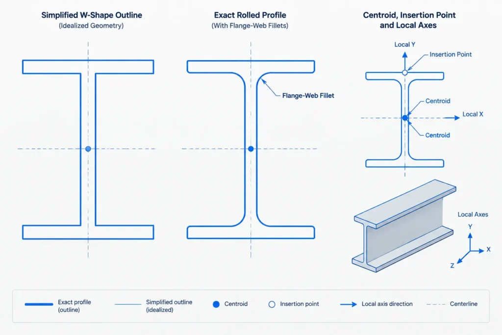
A CAD profile can be visually useful without reproducing every rolled contour. Many drafting blocks simplify fillets, flange-to-web transitions, HSS corners, or tapered surfaces. Those simplifications may be appropriate for plans, sections, clearance studies, or drawing production, but they can change CAD-calculated area and section properties.
Decide what the geometry is expected to do:
- Symbolic representation: communicates the shape family and orientation.
- Dimensional envelope: represents overall depth, width, and major faces for layout.
- Connection-clearance model: includes relevant fillets, corners, and usable flat regions.
- Property model: is intended for geometric property calculations and therefore requires appropriately controlled geometry.
Do not overwrite trusted published properties merely because a simplified CAD outline returns different values. Instead, determine whether the profile omits rolled features, uses nominal dimensions, contains overlapping regions, has open boundaries, or was scaled during insertion.
Check origin, orientation, and local axes
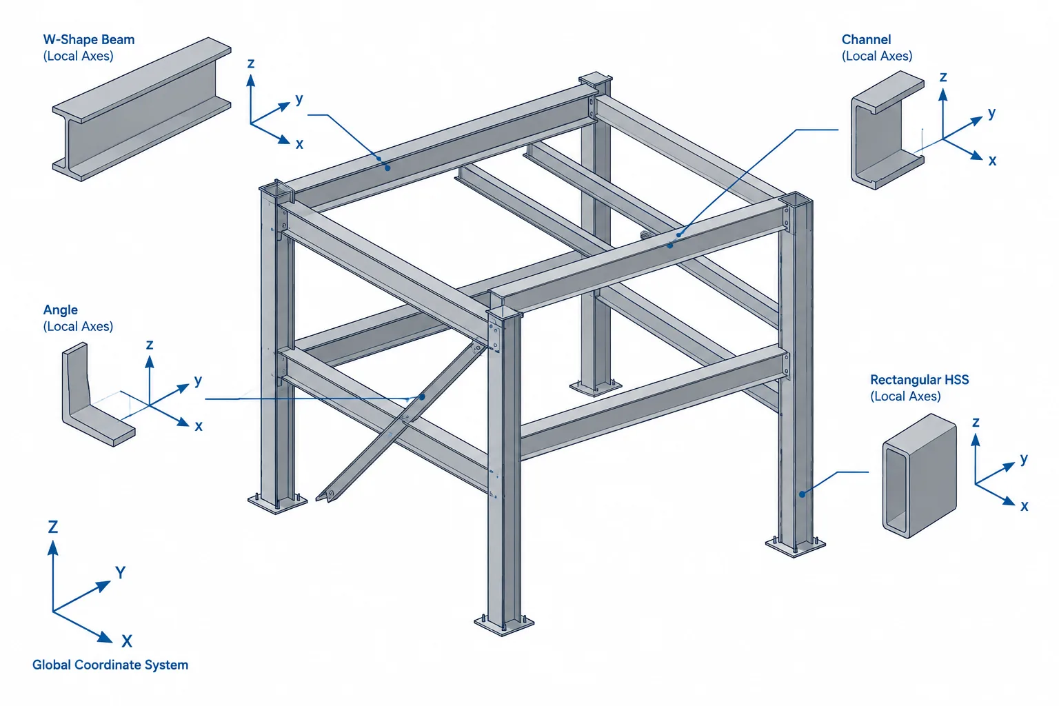
A section can have correct dimensions and still be placed incorrectly. Verify the insertion point and local-axis convention before using a block or model object as a layout reference.
Questions to ask include:
- Is the origin at the centroid, geometric center, web centerline, back of channel, heel of angle, or another datum?
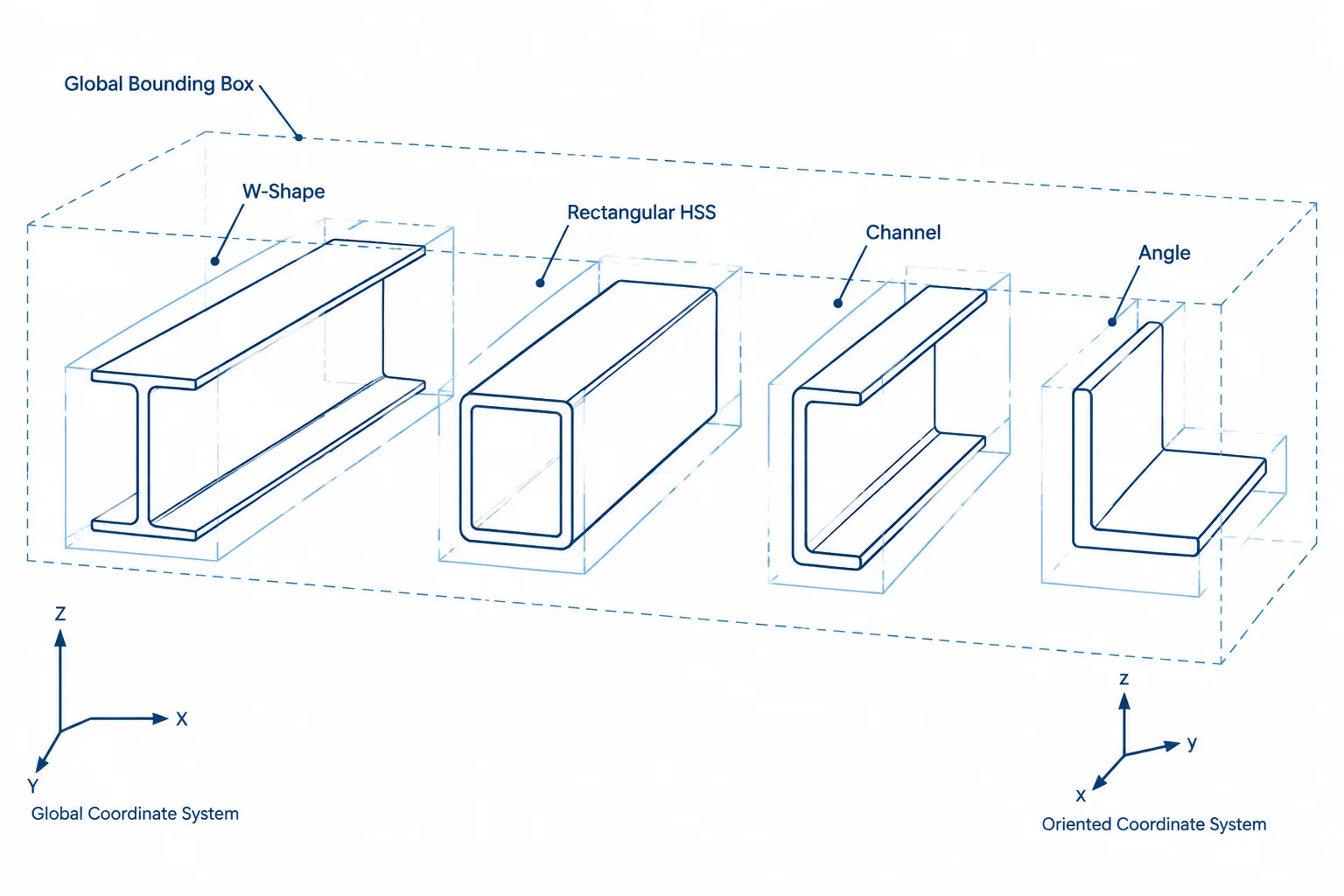
- Which direction is local x, y, or the member longitudinal axis?
- Has the section been mirrored?
- For an unsymmetric shape, did mirroring change the expected centroid or shear-center location relative to the model datum?
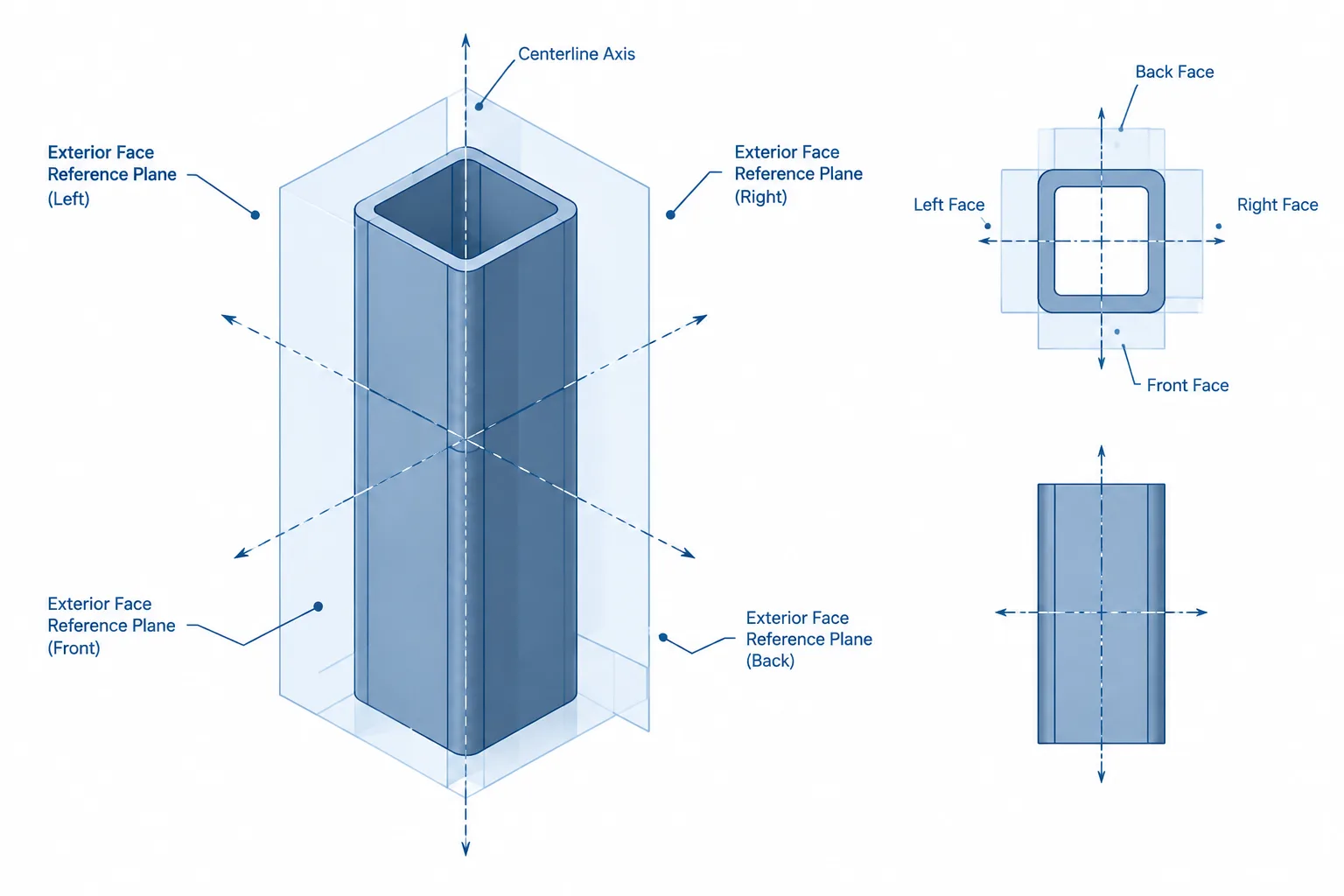
- Does a rectangular HSS have the intended long-side orientation?
- Are strong- and weak-axis property labels consistent with the displayed rotation?
This check is particularly important when geometry is exchanged between structural analysis, BIM, CAD, and fabrication systems. Each platform may assign local axes differently even when the member appears in the correct physical location.
Watch for incomplete exports and silent defaults
Database exports and software reports do not always include every field needed for detailing. A model may contain the nominal section name but omit detailing dimensions related to fillets, clear web regions, or centroid offsets. Conversely, a CAD library may contain accurate outlines but no controlled analytical properties.
Also review how the software handles an unrecognized designation. Some systems retain the previous section, substitute a generic profile, or create a user-defined member. Never assume that a successful import confirms a valid match. Open the resulting section record and compare it with the intended shape.
Create a compact verification record
A short verification record makes later revisions easier. It can be a spreadsheet row, model note, or controlled project checklist containing:
- Complete shape designation.
- Shape family and unit system.
- Reference dataset used for dimensions and properties.
- Key identity dimensions.
- Area and primary axis-property checks.
- CAD or model library source.
- Insertion point and local-axis convention.
- Date or revision identifier for the project record.
- Any known simplification, such as omitted fillets or idealized HSS corners.
The record should document what was checked without implying that the shape, connection, or CAD resource is approved for construction. Project suitability still depends on the governing design documents, engineering requirements, material availability, fabrication practices, and current reference information.
Recheck data when the member changes
A section substitution is not complete when only the designation text changes. Replace or confirm the CAD profile, analytical properties, member weight, connection interfaces, clearances, elevations, and bill-of-material entry. Shapes in the same nominal series can have different actual depths and flange geometry, so connected plates and surrounding construction may no longer align.
Automated schedules deserve the same review. If a member object changes but a manually entered label does not, the drawing can show two conflicting identities. Where possible, use coordinated data fields, but still inspect the published output.
A practical final check
Before releasing a drawing, model, calculation file, or takeoff, verify four things: identity, units, geometry, and axes. The designation must identify the intended product; the values must use consistent units; the graphical profile must be suitable for its intended purpose; and the origin and axis conventions must be understood.
This process takes less time than resolving a wrong-section issue after data has spread through drawings, material lists, connection details, and fabrication files. Shape tables remain the reference, while disciplined cross-checks help ensure that every downstream representation points back to the same steel section.