Flange and web thicknesses are among the most frequently used dimensions in structural steel shape tables. They influence connection geometry, clearances, section properties, fabrication decisions, and the appearance of a section in CAD. They are also easy to misuse when a simplified drawing is treated as an exact representation of a rolled shape.
In many shape references, tf identifies flange thickness and tw identifies web thickness. Those symbols are common, but users should always confirm the notation and dimensional diagram provided with the specific table. A dimension is meaningful only when its measurement direction and reference surfaces are understood.
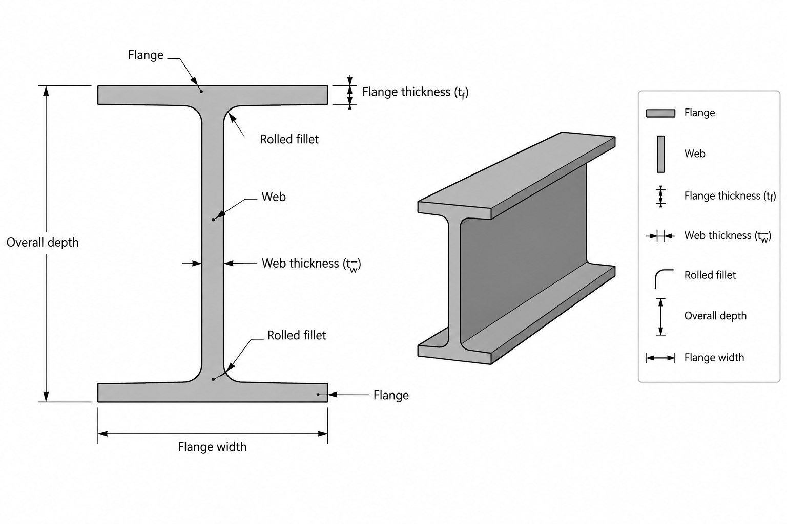
What Are the Flange and Web?
A W shape consists primarily of two flanges connected by a web. In the typical beam orientation, the flanges appear as the upper and lower horizontal elements, while the web is the vertical element between them.
- Flange: The broad projecting part of the section. In beam applications, the flanges commonly resist much of the bending stress associated with the major axis.
- Web: The connecting plate-like portion between the flanges. It commonly plays a major role in carrying shear and maintaining separation between the flanges.
- Flange thickness, tf: The tabulated thickness of a flange, measured in the direction indicated by the shape-table diagram.
- Web thickness, tw: The tabulated thickness of the web, generally measured perpendicular to the web faces.
This terminology also applies broadly to other I-shaped members, including many HP and S shapes. However, the flange geometry is not identical across every shape family. A drafter should not assume that a dimension or profile convention used for a W shape applies unchanged to an S shape, channel, tee, or built-up member.
How tf and tw Relate to Other Shape Dimensions
Flange and web thicknesses do not describe the complete cross-section by themselves. They work with overall depth, flange width, fillet geometry, and other dimensions to define the usable profile.
| Typical symbol | Common meaning | Practical use |
|---|---|---|
| d | Overall section depth | Member depth, elevations, framing clearances, and section placement |
| bf | Flange width | Plate fit, bolt-row layout, bearing area, and overall envelope |
| tf | Flange thickness | Plate alignment, connection geometry, weld access, and section modeling |
| tw | Web thickness | Web connection layout, cope geometry, weld placement, and section modeling |
| k-related dimensions | Distances associated with the flange-to-web transition | Clearance for plates, angles, bolts, welds, and fabrication tools |
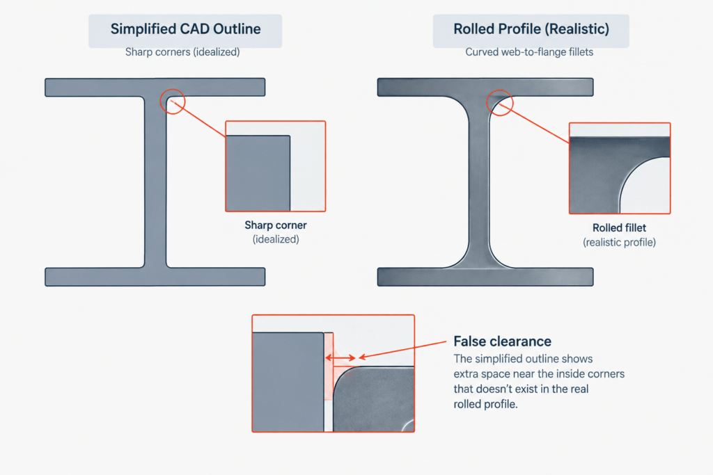
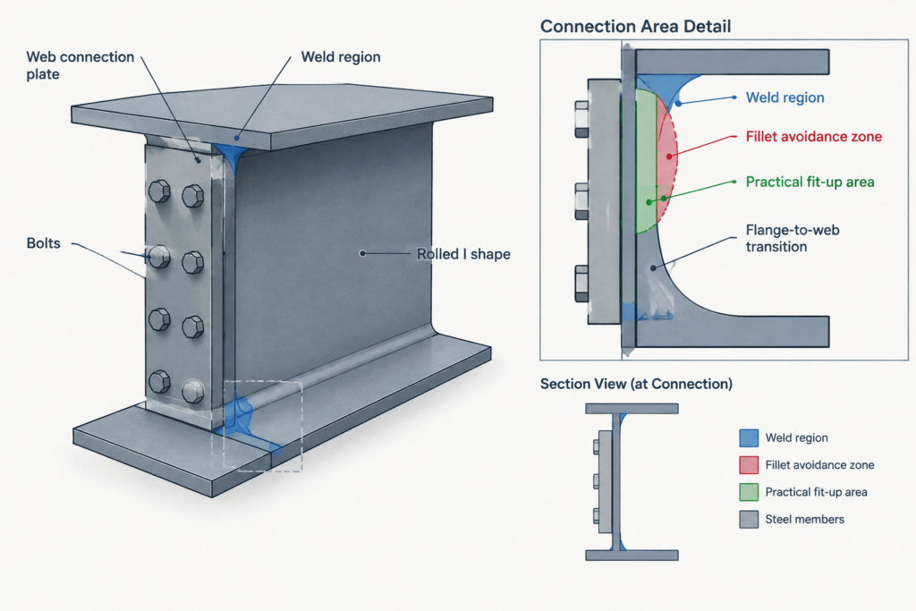
A rectangular outline made from d, bf, tf, and tw can be useful for diagrams, but it omits the rolled fillets where the web meets the flanges. Those curved transitions occupy real space and can control whether a plate, bolt head, washer, or weld can fit near the web-to-flange intersection.
Why the Fillet Region Matters
The web does not meet the flange at a perfectly sharp inside corner on a rolled I-shaped section. The transition includes a fillet created by the rolling process. Consequently, the clear flat portion of the web is less than the simple distance between the inner flange faces if the fillets are ignored.
This distinction is especially important when detailing:
- shear plates and double-angle web connections;
- transverse stiffeners;
- continuity plates and diaphragm components;
- beam copes and flange cuts;
- bolts or welds placed near the flange;
- fitted plates intended to bear against the web or flange.
A connection component should not be extended into the fillet region merely because a simplified CAD outline appears to provide room. Use the applicable detailing dimensions and project criteria to establish clearance. Final connection geometry must also be checked by the responsible designer and fabricator.
Are Flange and Web Thicknesses Constant?
W and HP shapes
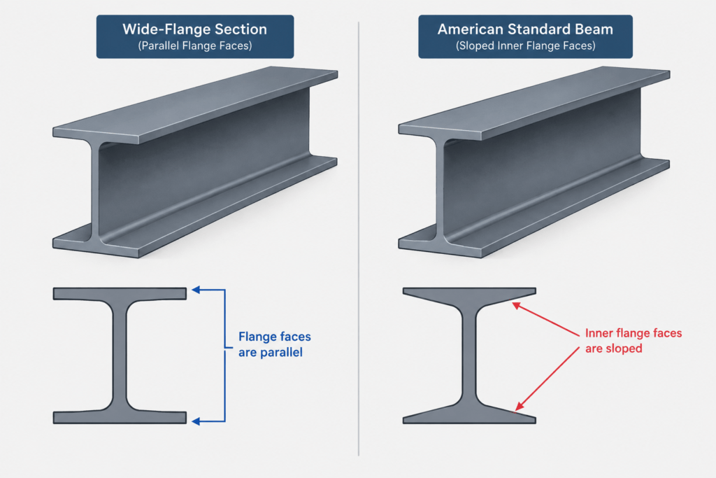
W and HP shape tables commonly present a single flange thickness and a single web thickness for each listed section. Their flange faces are represented as generally parallel for ordinary reference and drafting purposes. The actual rolled product is still subject to permitted manufacturing variation, and the transition regions are not square corners.
S shapes and some channels
American Standard beams and channels can have sloped inner flange surfaces. In these profiles, flange thickness cannot be interpreted as though the flange were a uniform rectangular plate across its full width. The table diagram and shape-family conventions are essential when creating a detailed section view or arranging a connection against an inner flange face.
Structural tees
A rolled structural tee is commonly produced by splitting an I-shaped section. Its stem corresponds to part of the original web, while its flange comes from one of the original flanges. Tee tables should be used directly because the tee depth, centroid location, and other properties are not obtained reliably by treating the shape as a generic plate assembly.
HSS and built-up sections
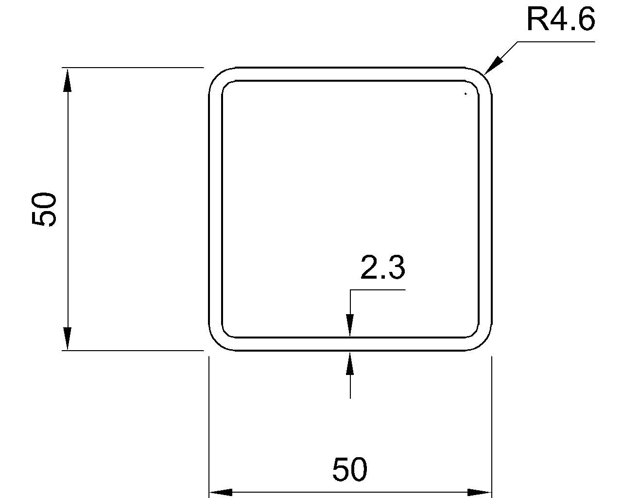
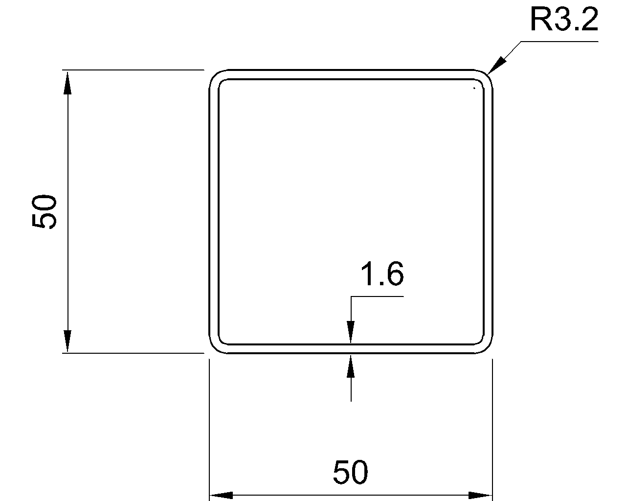
HSS walls are described by wall-thickness conventions rather than by I-shape flange and web symbols. Rounded corners also make a rectangular HSS different from four sharp-cornered plates. Built-up I sections, in contrast, may use separate plates for webs and flanges; their plate thicknesses and weld geometry come from the project documents rather than a rolled-shape table.
Using tf and tw in CAD
The appropriate modeling method depends on what the drawing needs to communicate. Not every plan, elevation, or section requires a fabrication-level profile.
Schematic section outlines
For framing plans, diagrams, and early coordination, a simplified profile may be sufficient. The web and flanges can be shown with straight edges while the shape designation carries the authoritative identity. The drawing should not imply that simplified square inside corners represent the actual rolled profile.
Connection and clearance details
For a connection detail, model enough of the actual geometry to evaluate interference. Include the flange-to-web transition when a plate, bolt, weld, or cut approaches that area. A verified section resource is preferable to tracing an unverified image or scaling a PDF illustration.
Reusable CAD blocks
A practical steel-shape library should store each section at full size in consistent drawing units. Use a defined insertion point, such as the centroid or another documented reference point, and identify the block by its complete shape designation. Avoid stretching one profile to represent another section because flange thickness, web thickness, fillets, and proportions do not necessarily change uniformly.
Keep the section profile separate from annotation when possible. This allows the same geometry to be reused in details with different scales, labels, and orientations.
Common Interpretation Errors
- Treating a table sketch as a scaled drawing: A dimensional diagram explains symbols; it is not necessarily proportional to the listed section.
- Ignoring the fillets: Sharp inside corners can create false clearance in connection layouts.
- Using tf as an elevation offset without checking the reference: Top-of-steel, bottom-of-steel, centerline, and flange-face elevations describe different locations.
- Applying W-shape geometry to another family: S shapes, channels, tees, angles, and HSS require their own dimensional conventions.
- Assuming the nominal model is a shop measurement: Tabulated dimensions identify and describe the shape, while actual rolled products can vary within applicable tolerances.
- Calculating listed section properties from a crude outline: Omitting fillets and other profile details can cause a modeled area, inertia, or weight to differ from published values.
A Reliable Detailing Workflow
- Confirm the complete shape designation and shape family.
- Use a consistent, verified shape-table source for all dimensions.
- Read the dimensional diagram before assigning meanings to symbols.
- Determine whether the drawing needs a schematic envelope or a detailed rolled profile.
- Include fillet and clearance geometry where connection components approach the flange-to-web transition.
- Check drawing units, insertion point, member rotation, and section orientation.
- Label the shape explicitly rather than relying on visual appearance.
- Coordinate connection clearances and fabrication assumptions with the project requirements.
Key Takeaway
Flange thickness tf and web thickness tw are fundamental shape-table dimensions, but they do not define the entire rolled profile. Correct use requires attention to the shape family, measurement diagram, flange-to-web fillets, manufacturing variation, and the level of detail required by the drawing. For general plans, a simplified outline may be appropriate. For connection detailing and interference checks, use verified geometry and preserve realistic clearance around the rolled transition regions.