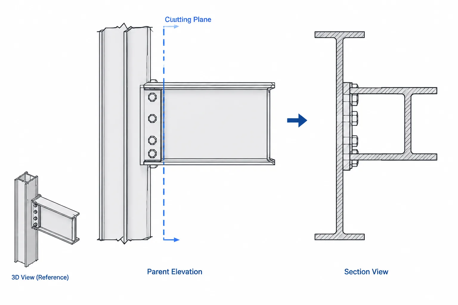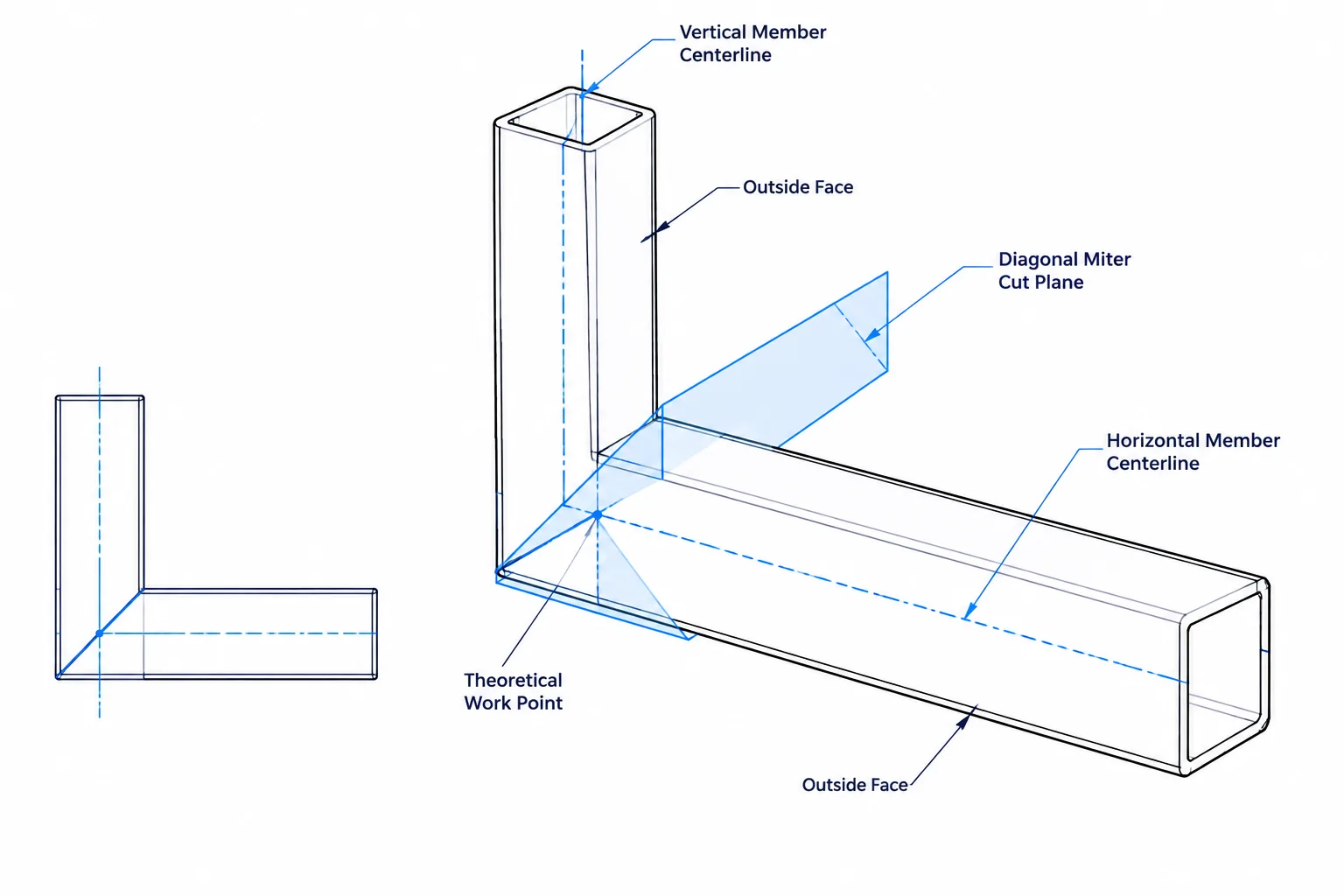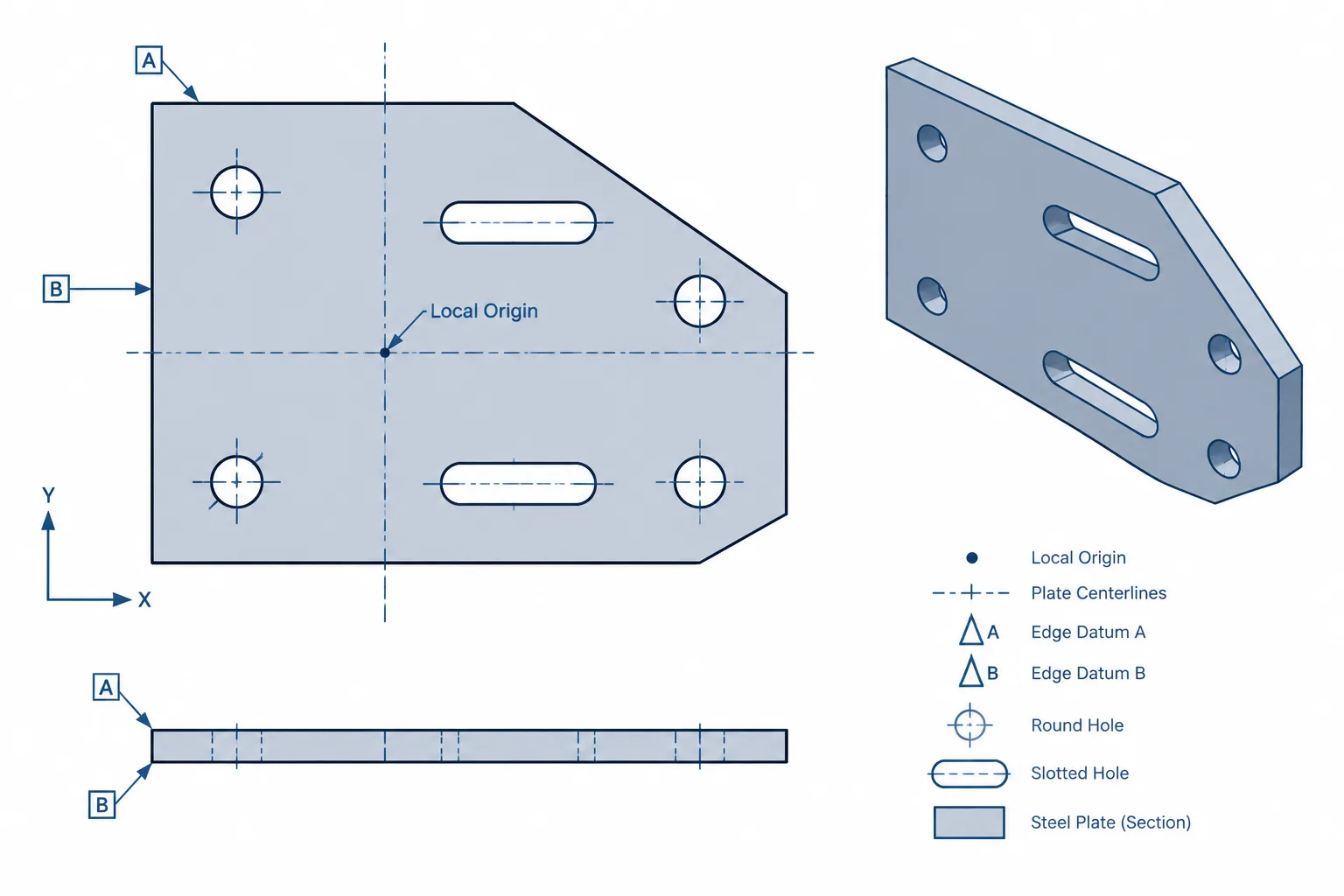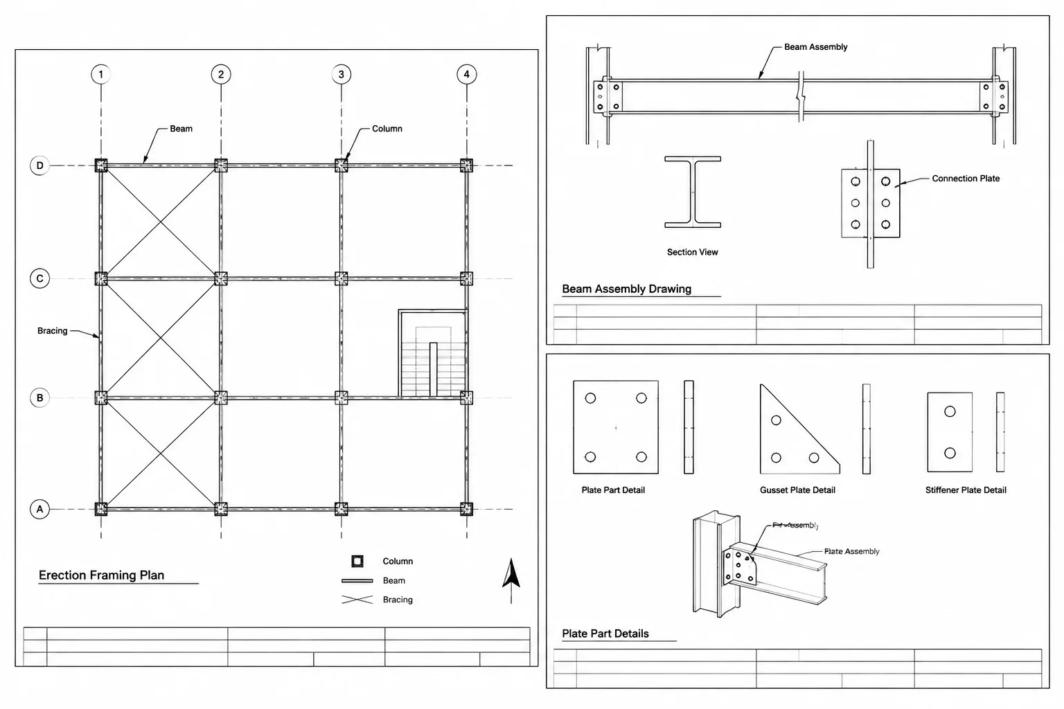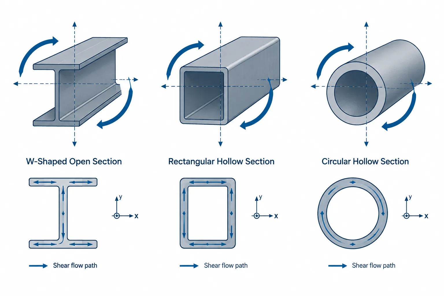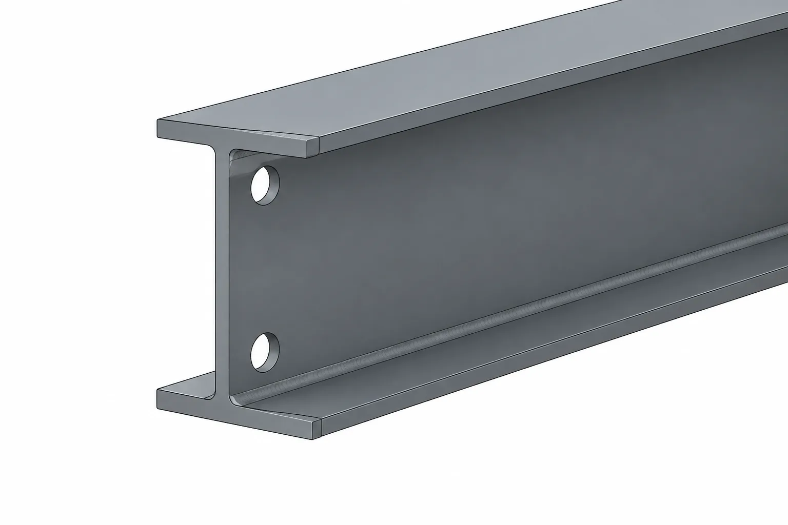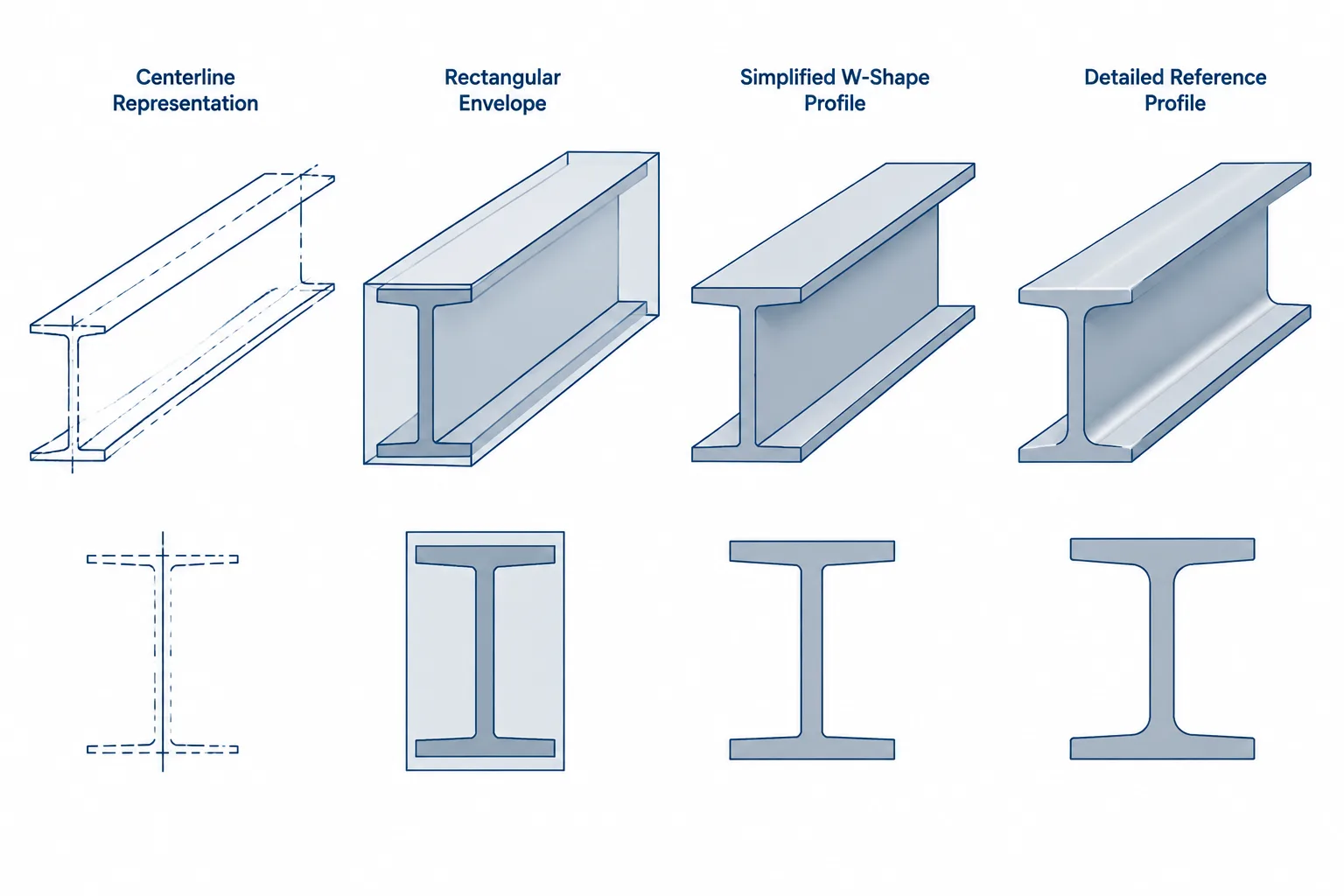
A steel member can be represented in CAD as a centerline, a rectangular envelope, a recognizable section profile, or a carefully constructed cross-section with fillets and corner radii. Each representation may be appropriate, but not for the same task.
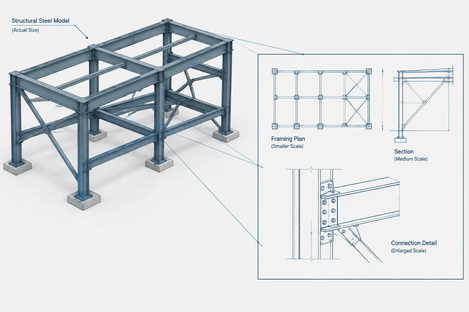
The key is to match the level of geometric detail to the decision being made. A framing plan may need only member centerlines and shape labels. A connection model may require flange and web faces. A clearance study may depend on rolled fillets or HSS corner regions. A section-property calculation requires even more discipline because small geometric assumptions can affect area, centroid location, moments of inertia, and torsional properties.
CAD geometry should therefore be treated as a purpose-specific representation, not automatically as the controlling definition of a steel product.
Four useful levels of steel representation
Most structural steel CAD geometry falls into one of four practical levels. The categories are not formal standards, but they provide a useful way to organize modeling and drafting decisions.
| Representation | Typical content | Useful for | Important limitation |
|---|---|---|---|
| Centerline or symbolic | Member axis, work line, or single-line framing symbol | Plans, elevations, framing layout, analytical coordination | Does not show physical width, depth, or connection clearance |
| Envelope geometry | Overall depth and width, often shown as a rectangle or bounding solid | Early coordination, rough clashes, spatial planning | Can overstate occupied material and conceal open regions |
| Recognizable section geometry | Webs, flanges, legs, walls, and approximate curved regions | General detailing, sections, connection layouts, visual coordination | May not reproduce published section properties |
| Property-grade reference geometry | Carefully developed profile intended to match a defined data source | Special calculations, profile validation, advanced section analysis | Still may not represent every manufactured variation or tolerance |
Using more detail is not always better. Unnecessary curves and faces can increase file size, slow display performance, complicate snapping, and create false confidence in dimensions that were never verified.
Centerlines are often the correct starting point
Structural framing is commonly laid out from grids, work points, elevations, and member centerlines. At this stage, the primary questions concern member location, direction, span, slope, and connectivity. A detailed cross-section may add visual complexity without improving those decisions.
Centerline geometry is especially effective for:
- Establishing framing relationships and work-point locations
- Checking member continuity and analytical alignment
- Creating uncluttered plans and elevations
- Coordinating sloped or skewed framing paths
- Assigning shape designations without drawing full profiles
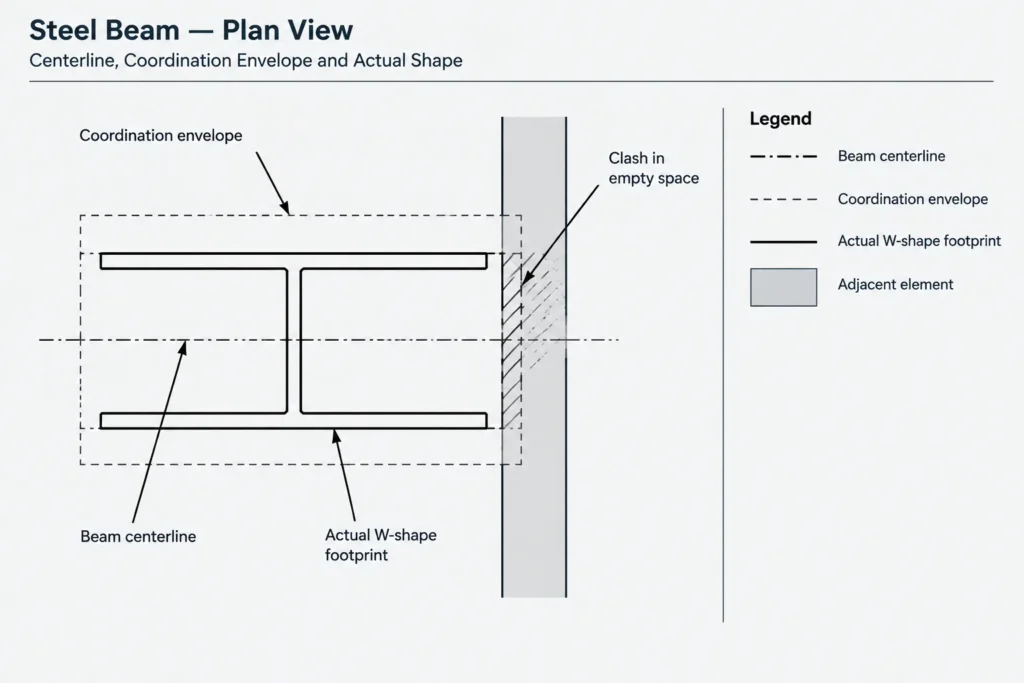
A centerline is not a physical edge. It should not be used by itself to judge clear distance from a wall, pipe, opening, plate, or adjacent member. Before making those checks, the appropriate section envelope or face geometry must be added.
Envelope models are useful but intentionally conservative
An envelope represents the overall space occupied by a section without reproducing its complete profile. A W-shape might be modeled as a rectangular prism based on overall depth and flange width. Similar envelopes can be created for channels, angles, tees, and HSS.
This approach is valuable during early coordination because it is simple and fast. It can identify obvious conflicts, such as a member passing through another system. However, it can also report clashes in areas where no steel actually exists. The open region beside a W-shape web, the inside of a channel, or the space between angle legs may be filled by the envelope even though the real profile leaves that area open.
Envelope-based clashes should therefore be classified as screening results. A reported interference should be reviewed with more representative geometry before anyone changes the design or detailing.
Recognizable profiles support most detailing work
For many shop and coordination tasks, a recognizable profile provides the best balance between usefulness and model efficiency. It shows the principal material boundaries while avoiding unnecessary manufacturing-level complexity.
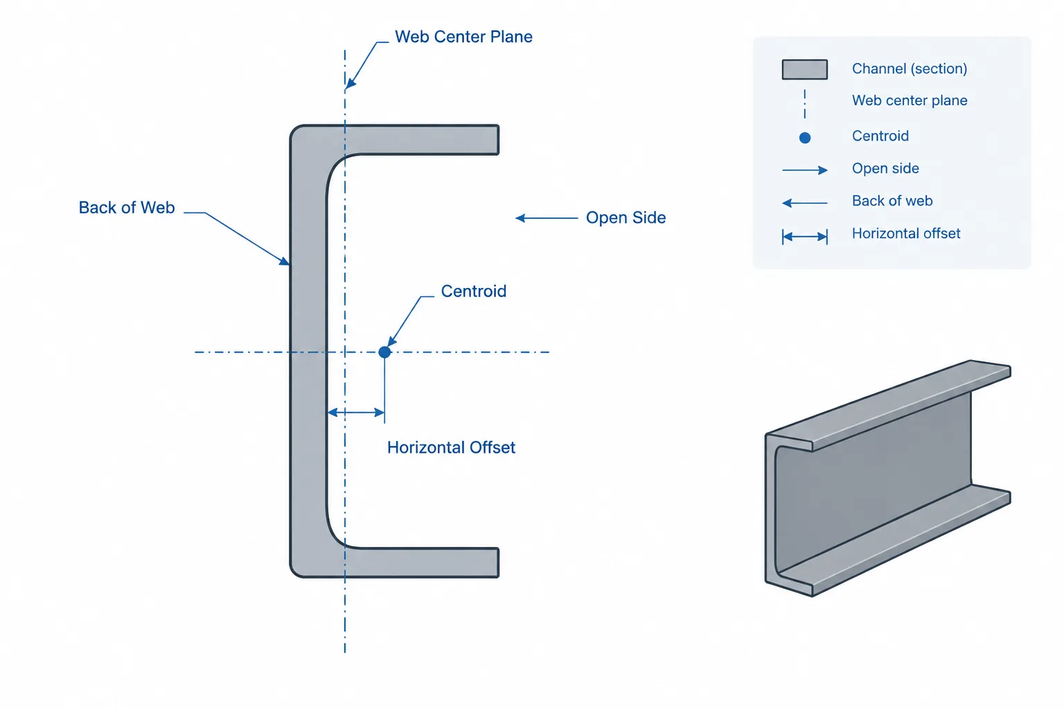
W-shapes, channels, tees, and HP shapes
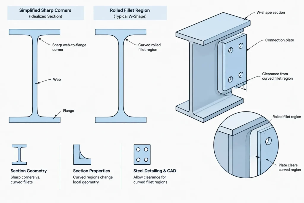
These profiles generally need visible flange and web faces. Curved web-to-flange transitions may be included when they influence fit, but they should not be guessed from an arbitrary drawing radius. Published detailing dimensions can help identify protected fillet regions even when the model does not reproduce the complete rolled contour.
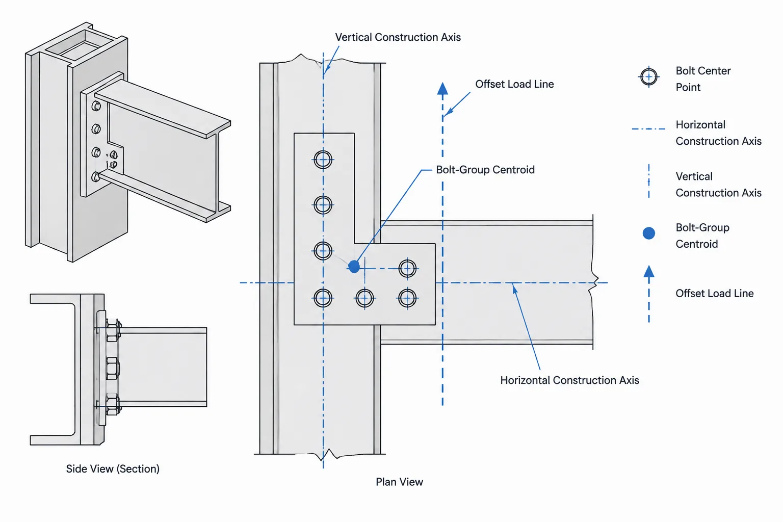
A square inside corner can be acceptable for a small-scale diagram, but it may be misleading in a connection model. Plates, welds, bolt heads, stiffeners, and cope cuts placed near the web-to-flange transition require deliberate clearance from the actual or specified fillet region.
Angles and structural tees
An angle should preserve its unequal or equal leg orientation, heel location, and thickness direction. A simple outside rectangle loses the open-side geometry and can hide whether a connected leg is correctly placed.
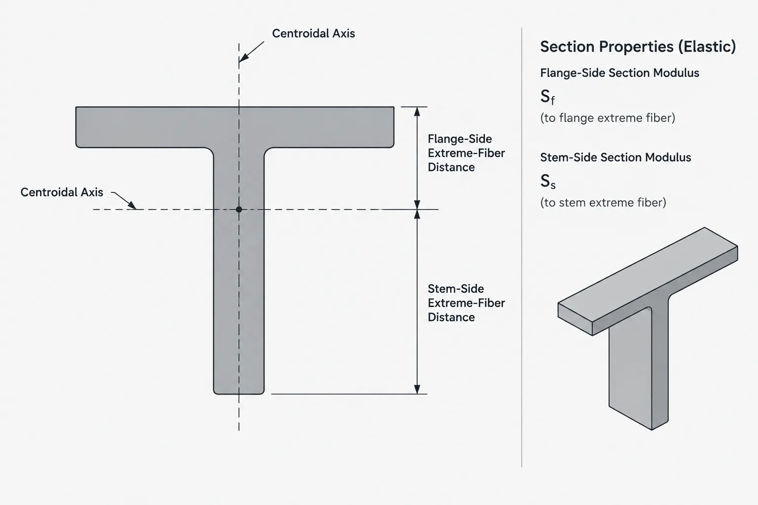
Structural tees also require clear stem and flange orientation. Their geometry should not be inferred from a generic T symbol when flange width, stem depth, or rolled transition clearance affects a connection.
HSS profiles
Rectangular and square HSS should not automatically be drawn as sharp-cornered boxes. Their curved corner regions affect clear openings, insert fit, plate placement, and local detailing. At the same time, a CAD corner arc should not be assumed to define the exact manufactured surface unless it comes from an appropriate verified source.
For round HSS, the outside diameter may be sufficient for general coordination, while wall geometry becomes relevant for end connections, slots, inserts, and sections showing the hollow interior.
When section-property calculations need a different model
A profile that looks correct on screen may not produce the same properties as a published shape table. Differences can result from simplified fillets, idealized corners, assumed wall geometry, curve segmentation, duplicate boundaries, or the treatment of rolled transitions.
Before using CAD to calculate area, centroid, moment of inertia, section modulus, or related properties, document:
- The source of every controlling dimension
- Whether fillets and corner regions are included
- Whether the profile is open, closed, or composed of overlapping regions
- The coordinate system and axis orientation
- The drawing units and conversion method
- The expected comparison source and acceptable purpose of the result
A published shape property and a property extracted from simplified CAD geometry answer different questions. The published value belongs to its defined reference data, while the CAD result describes the geometry actually drawn. Agreement should be verified rather than assumed.
Avoid the phrase “exact steel profile” without qualification
Calling a CAD block or model exact can imply more certainty than the geometry supports. Rolled and formed products have permitted variation, and many reference profiles are based on nominal dimensions rather than a scan of a particular manufactured member.
More useful descriptions include:
- Symbolic member representation
- Nominal section envelope
- Simplified detailing profile
- Reference profile based on verified shape data
- Calculation profile with documented geometric assumptions
These labels tell the next user what the object was built to do. They also reduce the risk that a lightweight coordination block will later be used for an unsupported fabrication or engineering decision.
CAD layer and object-management practices
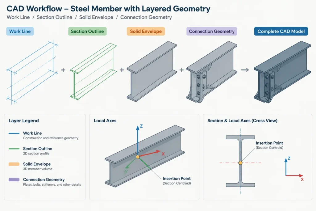
Different representations can coexist in the same workflow if they are clearly managed. A practical model may contain a member centerline, a simplified solid, and selected detailed connection geometry.
Useful controls include:
- Separating centerlines, envelopes, section outlines, and connection components by layer or object class
- Storing the shape designation as object data or an attribute rather than relying only on nearby text
- Defining a consistent insertion point, such as the centroid, member work line, or a documented face
- Recording local-axis direction and section rotation
- Preventing unverified profiles from being reused as calculation templates
- Keeping source notes with custom blocks or profile libraries
Insertion points deserve particular attention. Two visually identical profiles can behave very differently if one is inserted at its centroid and another at a corner or flange face. The chosen origin should match the placement workflow and remain consistent throughout the library.
A practical selection workflow
Before choosing or creating steel shape geometry in CAD, ask what must be measured or coordinated.
- Define the task. Is the object needed for framing layout, drawing presentation, clash detection, connection detailing, fabrication geometry, or property calculation?
- Identify the controlling features. These may be the centerline, overall envelope, flange faces, web face, HSS wall, corner region, or a connection interface.
- Select the least detailed representation that preserves those features. Avoid modeling complexity that does not support the task.
- Verify the data source. Confirm dimensions and properties against the project’s accepted references.
- Label assumptions. State whether curved regions, tolerances, and thicknesses are nominal or simplified.
- Upgrade geometry selectively. Add detail around connections and clearance-sensitive zones rather than making the entire model unnecessarily complex.
Geometry should communicate purpose
The most useful steel model is not necessarily the one with the most edges. It is the one whose geometry is appropriate, traceable, and clear about its limitations.
Use centerlines for layout, envelopes for early spatial screening, recognizable profiles for most detailing, and carefully documented profiles for geometric property work. When connection fit, fabrication, or installation depends on a surface, radius, or clearance, verify that feature independently instead of trusting a generic CAD object. This approach keeps structural steel drawings efficient while preserving dimensional control where it matters.