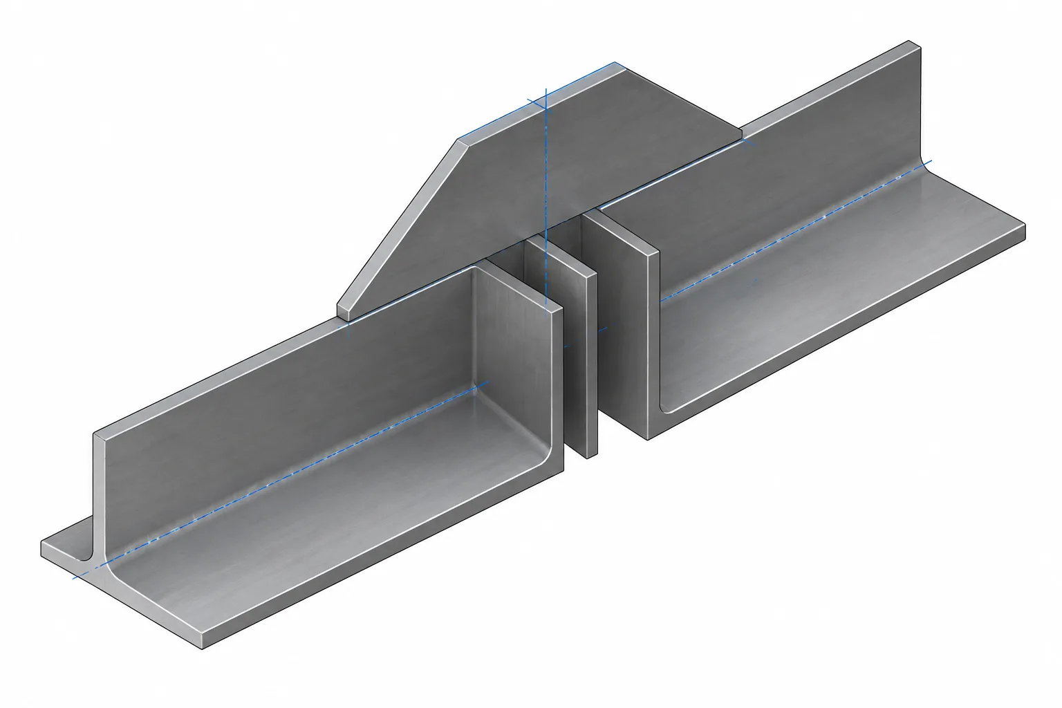
Built-up double-angle members appear in trusses, bracing systems, lattice work, towers, and other structural assemblies where two angles act together. The concept looks simple: place one angle on each side of a gusset or arrange two angles around a common member axis. In practice, the member cannot be detailed reliably from an angle designation and overall length alone.
The spacing between the angles, the connected legs, the location of gussets or separators, and the stitch connections all affect fabrication geometry. They can also affect the member’s section properties, stability, force transfer, and behavior as a built-up component. Drawings therefore need to define more than a generic note such as “two angles back-to-back.”
What Is a Built-Up Double-Angle Member?
A built-up double-angle member consists of two individual angle shapes connected at intervals or through connection plates so that they function as one structural member. The angles may be identical, but identical component shapes do not guarantee a symmetric built-up section. Symmetry depends on their orientation and spacing.
A common arrangement places the angles on opposite faces of a gusset plate. Another uses filler plates, separator plates, batten plates, bolts, or welds to maintain a specified gap. Some assemblies bring the angles into direct contact, while others require a deliberate space for connection material or geometric alignment.
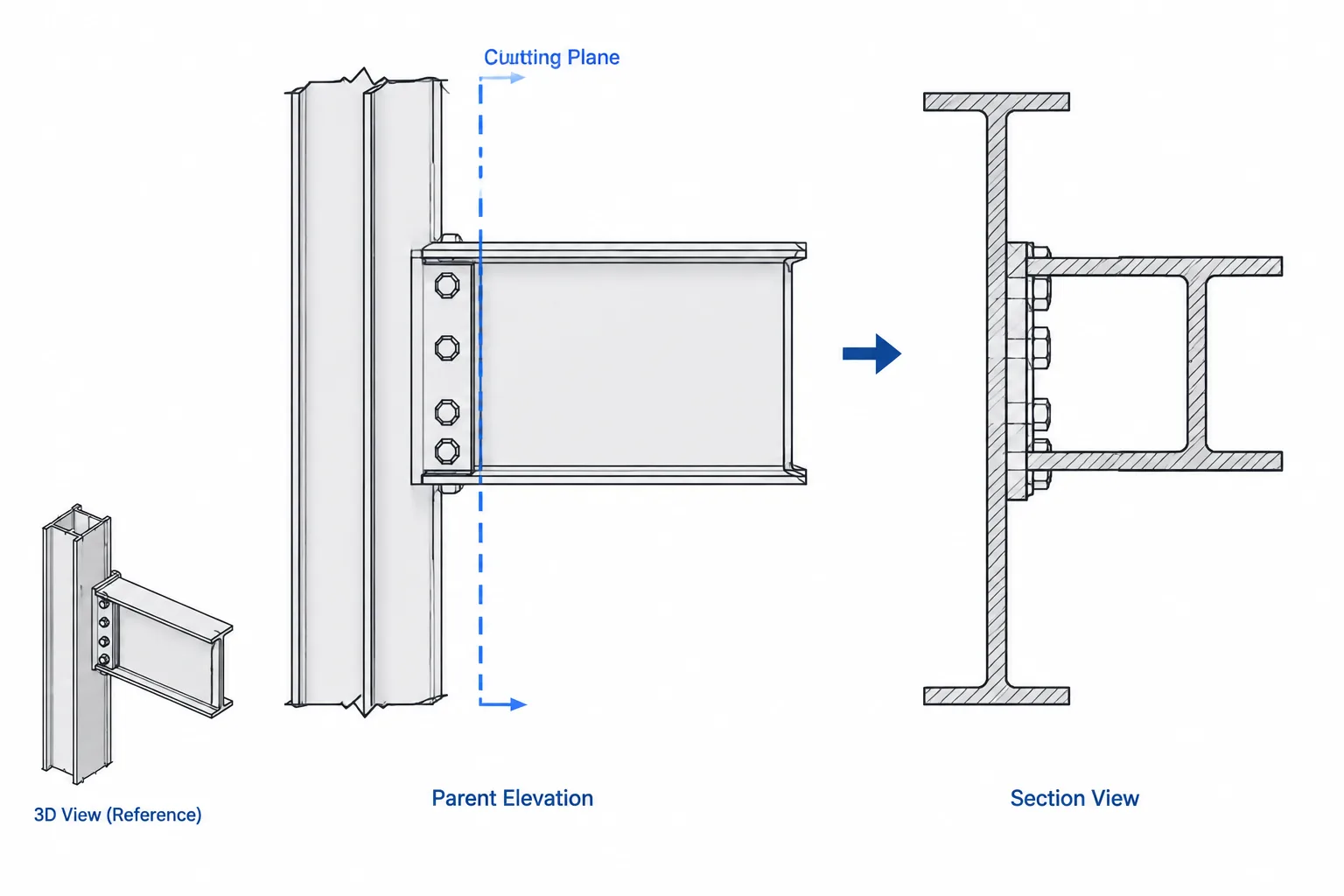
Terms such as back-to-back, toe-to-toe, and outstanding legs can be useful, but words alone may be interpreted differently. A section view is usually the clearest way to establish orientation.
The Geometry That Must Be Defined
Angle orientation
Each angle has two legs, an outside corner at the heel, and toes at the free edges. For unequal-leg angles, the drawing must also establish whether the long or short leg is connected. Mirroring an unequal-leg angle can move its centroid, outstanding leg, bolt gage, and free edge even when the member work line remains unchanged.
A complete section or end view should make the following conditions visible:
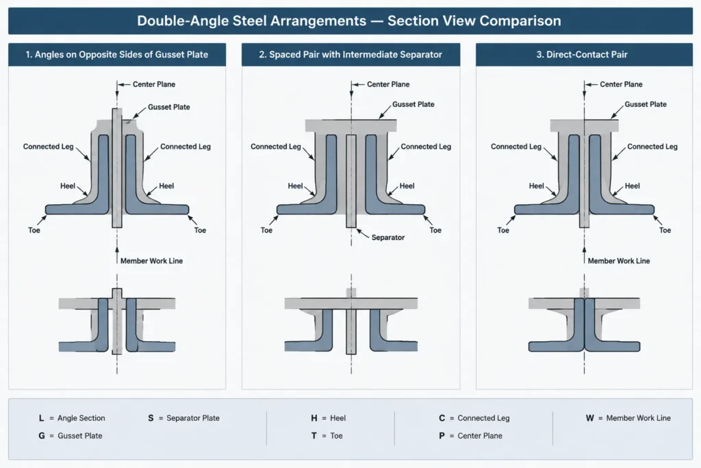
- Which legs face inward or outward
- Which legs connect to gussets, splice plates, or end fittings
- Whether the two angles are mirrored about a center plane
- Whether the long or short legs are connected
- The direction of the angle toes and outstanding legs
Gap and separator thickness
The clear distance between angles is a controlling assembly dimension. It may be established by the thickness of a gusset, a continuous filler, intermittent separators, washers, or another detailed component. A nominal centerline representation does not define this physical gap.
Detailers should identify exactly what a spacing dimension measures. Possible references include inside faces of connected legs, backs of angles, member work lines, or the center plane between components. These are not interchangeable datums.
When the space is intended to receive a gusset or splice plate, the coordinated geometry includes more than the plate’s nominal thickness. Fabrication tolerances, coating, fit-up method, welds, bolt installation, and the intended assembly sequence may also matter. The required allowance must come from the project design and fabrication criteria rather than an assumed CAD clearance.
Member work line
The work line of a double-angle member may pass through the center plane between the angles, the centroid of the built-up section, or a connection work point established by the structural layout. Those locations can coincide for some symmetric arrangements, but they should not be assumed to coincide in every configuration.
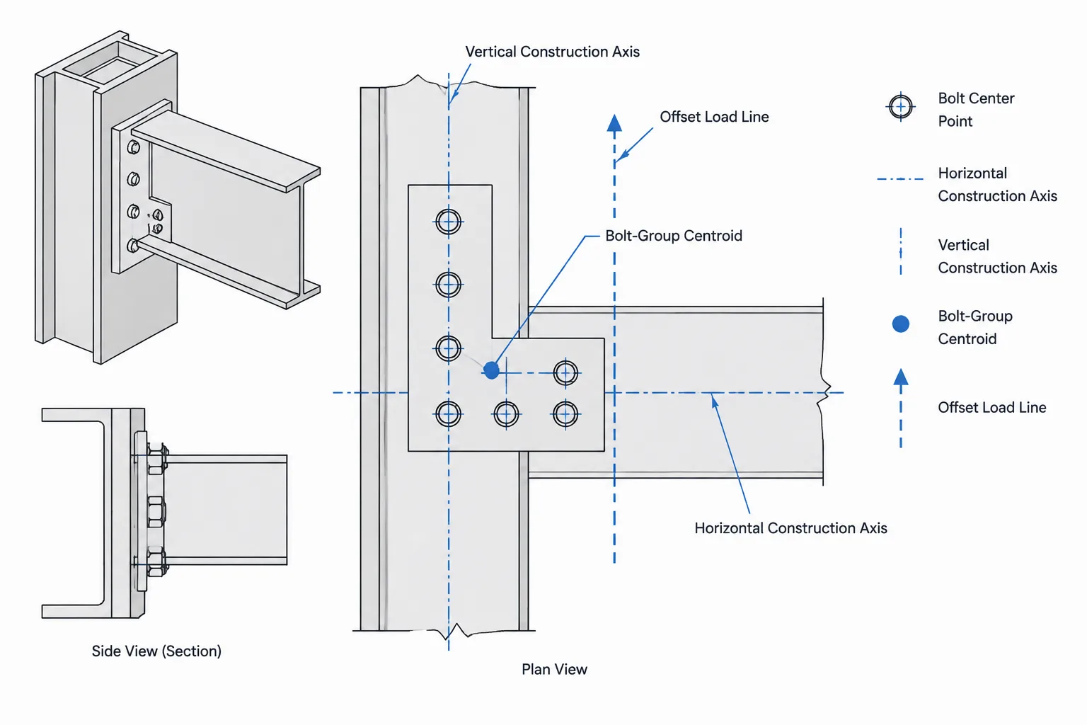
If the member connects to a gusset through only certain legs, the connection plane may be offset from the centroid of each individual angle. This can introduce connection eccentricity even when the overall assembly appears balanced in elevation.
Stitch Connections and Intermediate Separators
Connections between the component angles are often called stitch connections. Depending on the assembly, they may consist of bolts, short welds, separator plates, tie plates, or another engineered arrangement. Their purpose may include maintaining spacing, limiting independent movement, providing stability, or making the pair act as the intended built-up member.
Stitch spacing and connection type are design information. They should not be selected solely to make the model look complete or to simplify fabrication. The engineer’s details or project criteria should define the required arrangement.
Shop drawings should communicate:
- Stitch connection type and location
- Quantity and pattern of bolts or extent of welds, as specified
- Separator or filler plate size and orientation
- Longitudinal dimensions from a stable member datum
- Whether a stitch location is typical or intentionally varies
- Areas where intermediate connectors must avoid gussets, splices, or other attachments
A separator shown only in an elevation can be easy to misread. A section should show whether it fits between the angles, crosses their outstanding legs, or attaches to only one leg of each component.
Direct Contact Is Not the Same as a Spaced Pair
Two angles touching each other create a different fabrication condition from two angles separated by plates. Direct contact can create narrow interfaces that are difficult to inspect, prepare, coat, or drain. A spaced pair introduces additional parts and may create pockets that collect moisture or debris.
These conditions are especially important when the member will be galvanized, exposed to weather, or coated after assembly. Drainage, venting, access, and sealed interfaces require project-specific coordination. The detailer should not convert a spaced assembly to direct contact—or add an arbitrary gap—without approval.
Section Properties of a Double-Angle Assembly
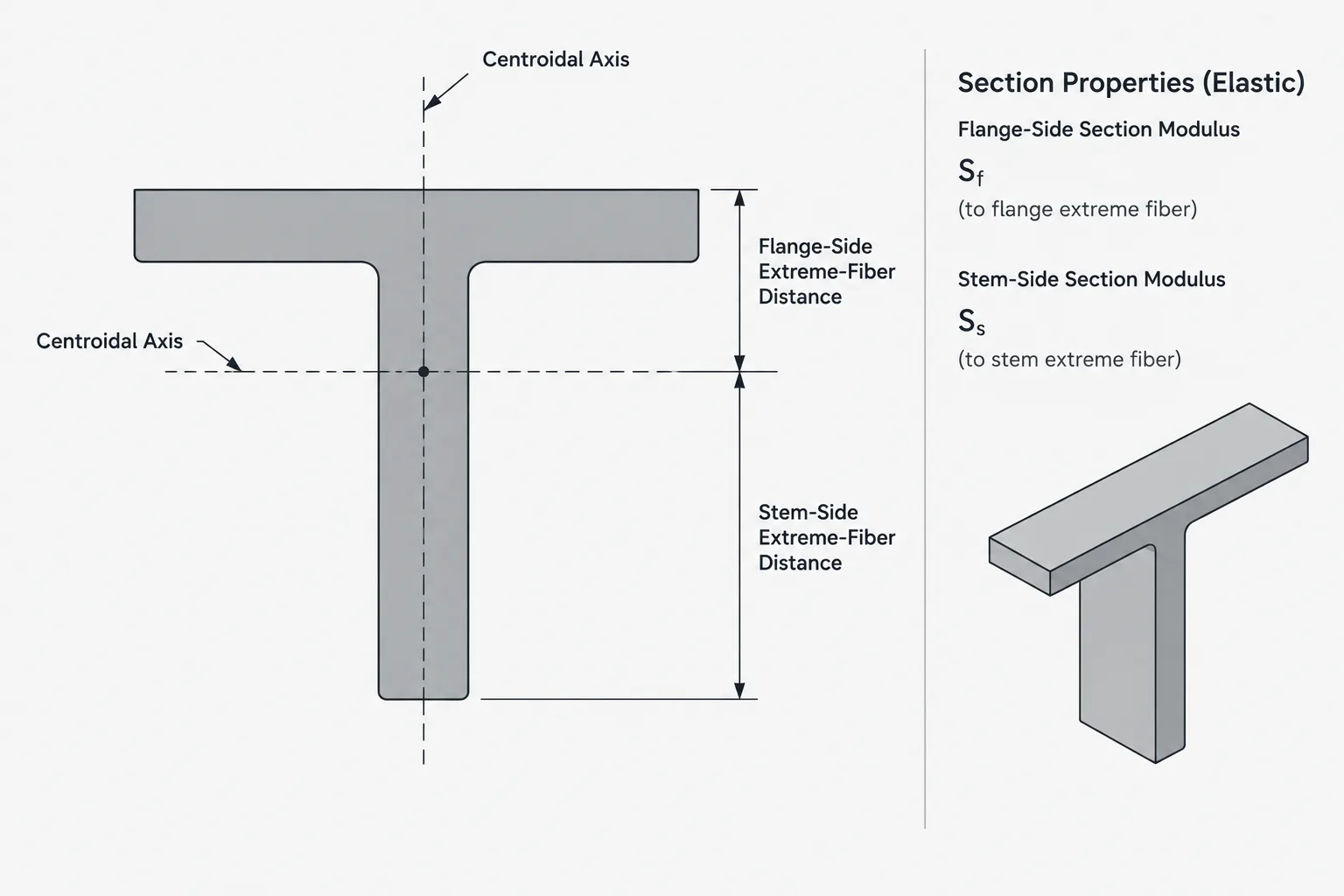
The properties of a built-up pair are not generally obtained by doubling every property of one angle. Total area and weight can be summed when both component shapes are identical, but centroid location, moments of inertia, radii of gyration, product of inertia, and principal-axis properties depend on orientation and spacing.
The parallel-axis contribution can be significant when the angles are separated. Increasing the distance between component centroids can increase moment of inertia about an axis even though the steel area remains unchanged. The effect is directional: spacing that improves one axis may have little effect on another.
Property calculations should use the actual assembled geometry and clearly defined reference axes. They should also reflect the structural assumptions about how the components are connected and whether they can act together as intended.
| Property or condition | What controls it | Common detailing risk |
|---|---|---|
| Total area and weight | Component shapes and added plates | Omitting separators or fillers from material lists |
| Built-up centroid | Angle orientation, size, and spacing | Assuming it lies on a drawn member centerline |
| Moment of inertia | Individual properties plus component offsets | Simply doubling a single-angle value |
| Principal axes | Complete assembled geometry | Using the leg directions as principal axes without checking |
| Connection eccentricity | Load path relative to connection and centroid | Centering a gusset visually rather than from design geometry |
End Connections and Gusset Coordination
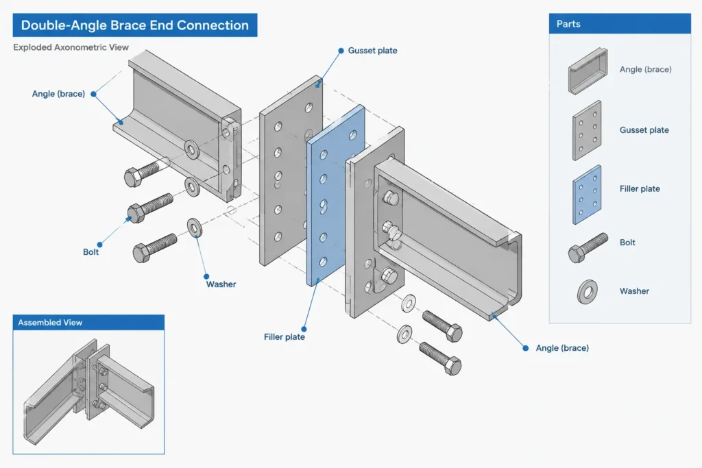
Double-angle members commonly frame around gusset plates. The gusset may fit between the angles, lie outside the pair, or connect through additional plates. The end detail must coordinate angle spacing with gusset thickness, bolt layout, edge conditions, weld access, and erection sequence.
When a gusset fits between angles, the section view should identify whether the angle backs bear against the gusset faces or whether a defined clearance is intended. Bolt grip must account for the actual ply stack, including both angles, the gusset, fillers, and washers where specified.
The member end may also require clips, copes, chamfers, or offsets to clear another chord, column, plate, or weld. These features should be dimensioned from stable datums rather than inferred from an overall member outline.
CAD Modeling Workflow
A dependable CAD or BIM workflow starts with two separate angle objects rather than a single symbolic double-angle profile. Separate objects preserve component orientation and make it easier to generate part drawings, material lists, connection views, and fabrication data.
- Establish the member work line. Confirm its endpoints and relationship to structural work points.
- Place the first angle. Set the connected leg, toe direction, and longitudinal orientation.
- Mirror or place the second angle deliberately. Verify the result in a true section instead of relying on a plan or elevation.
- Apply the specified spacing. Use a named reference plane or face-based dimension that can be checked later.
- Add gussets, separators, and fillers as physical parts. Do not represent them only with notes if they affect fit or material quantities.
- Lay out stitch connections from a defined end datum. Check both member ends because end conditions may not be symmetric.
- Review interference and access. Examine bolts, welds, adjacent plates, tools, coatings, and erection paths.
A model centerline is not sufficient quality control. Create section views at end connections, intermediate separators, and any location where spacing changes.
Drawing Checks Before Release
- Does a section clearly establish both angle orientations?
- Is the connected leg identified for unequal-leg angles?
- Is the gap dimension tied to unambiguous faces or center planes?
- Do filler and separator thicknesses agree with the assembled spacing?
- Are stitch locations dimensioned from a stable datum?
- Does the bill of material include both angles and every separate plate?
- Are left-hand and right-hand assemblies distinguished where necessary?
- Does the end connection use the correct ply stack and grip geometry?
- Have coating, drainage, access, and erection conditions been coordinated?
- Were built-up section properties based on the actual orientation and spacing?
Practical Takeaway
A double-angle member is an assembly, not merely a shape designation with a quantity of two. Its performance and fit depend on the relationship between the component angles, connection plates, work line, and intermediate connectors. Clear section views, explicit spacing datums, separate part modeling, and coordinated stitch details make the member easier to calculate, fabricate, inspect, and erect.