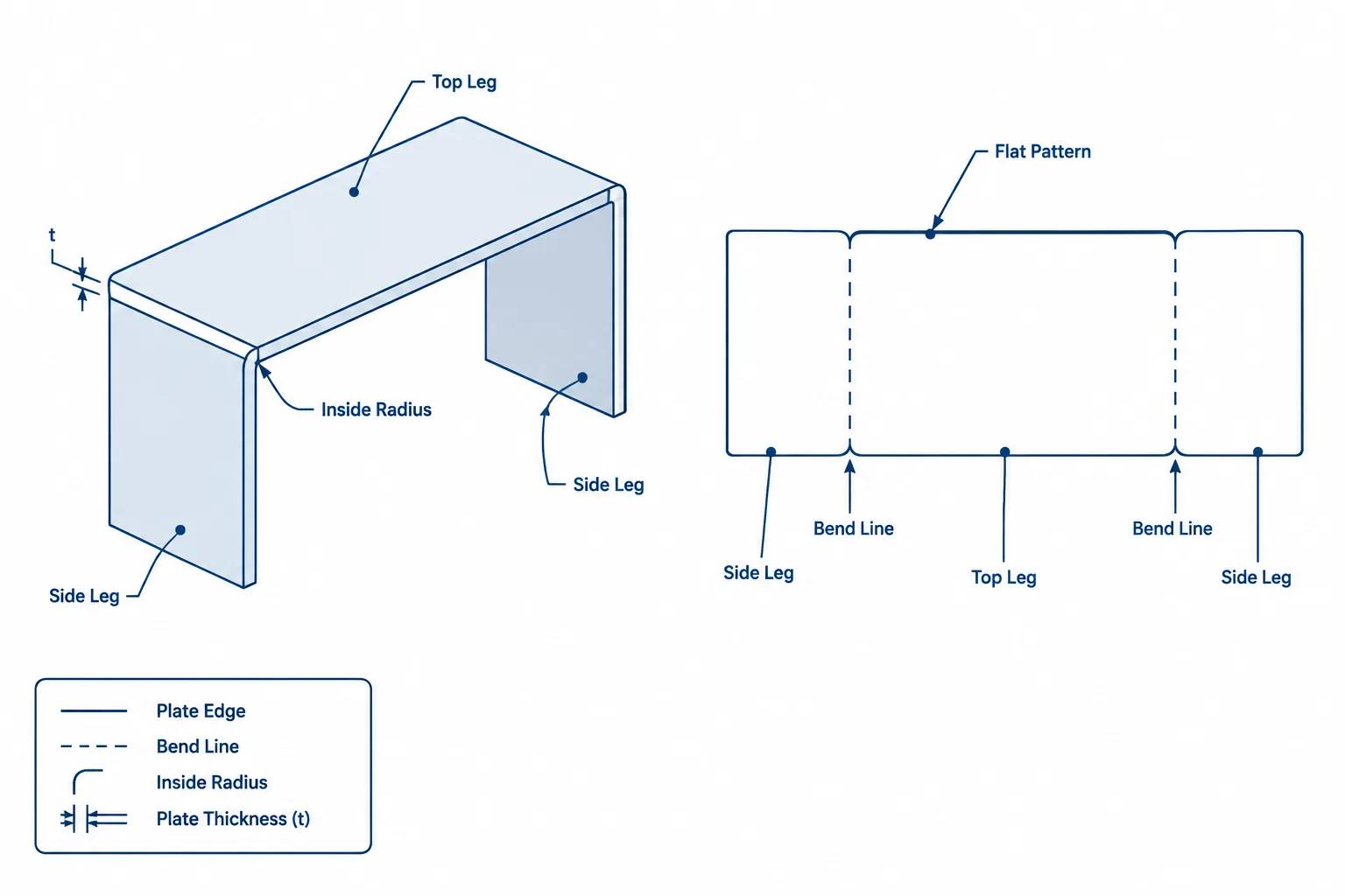
Bent plates appear throughout structural steelwork as connection angles, closure plates, pour stops, bent caps, equipment supports, edge plates, and other fabricated components. Although a bent plate can look simple in its finished form, its drawing must communicate both the final geometry and enough manufacturing information for the fabricator to develop the flat blank correctly.
The central detailing issue is that a bend is not a zero-width corner. Material follows a curved path around an inside bend radius, while the inside surface shortens and the outside surface lengthens. As a result, adding the finished leg dimensions does not necessarily produce the correct flat length. A reliable drawing distinguishes finished dimensions from developed dimensions and avoids silently assuming how a shop will calculate bend allowance.
Finished geometry and flat geometry serve different purposes
The finished view describes the part after bending. It establishes the plate legs, included angle, orientation, hole locations, edge relationships, and connection interfaces. The flat pattern describes the blank before bending and may show its overall developed length, bend lines, hole locations, and forming direction.
These two representations are related, but they are not interchangeable. A finished outside-to-outside dimension includes the effects of plate thickness and bend geometry. A flat length follows the developed material through the bend region. Converting between them requires more information than the visible leg lengths alone.
For many structural projects, the preferred approach is to define the required finished geometry and allow the fabricator to establish the developed blank using its approved forming process. If a flat pattern is supplied, the drawing should make clear whether its dimensions are controlling, reference-only, or subject to fabricator verification.
Key terms used in bent plate detailing
| Term | Practical meaning |
|---|---|
| Inside bend radius | The radius at the inside surface of the formed corner. It affects the developed length, fit, and forming method. |
| Outside radius | The curved outside surface of the bend. It is related to the inside radius and plate thickness but should not be confused with the inside radius. |
| Bend angle | The amount through which the plate is formed. Drawing conventions may instead describe the final included angle, so the intended meaning must be evident. |
| Tangent point | The location where a straight leg transitions into the bend radius. |
| Bend line | A layout line on the flat pattern used to identify the bend location. Its exact shop meaning depends on the forming and layout method. |
| Neutral axis | A conceptual layer through the thickness whose developed length is used when calculating the bend region. |
| Bend allowance | The developed arc length assigned to the bend region along the selected neutral axis. |
| Bend deduction | A value used to convert specified finished leg dimensions into a flat blank length under a particular dimensioning method. |
Inside, outside, and tangent dimensions
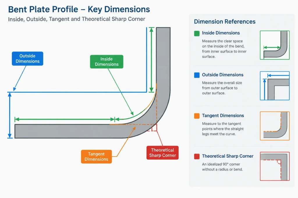
A major source of bent plate errors is an unclear dimension reference. A leg may be measured to an outside corner, an inside corner, a theoretical sharp corner, or a tangent point. Those references do not produce the same flat development.
Outside dimensions
Outside dimensions are often convenient when the part must fit around another component or align with an exterior face. However, an outside dimension extends to the outside bend envelope, not directly to a neutral-axis tangent. The development method must account for the radius and thickness.
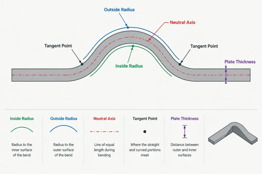
Inside dimensions
Inside dimensions can directly describe a required clear opening or fit between plate faces. They still do not, by themselves, define the flat length because the bend radius and forming assumptions remain relevant.
Tangent dimensions
Tangent dimensions locate the straight portions relative to the curved bend. They are geometrically useful for development calculations, but tangent points may be less convenient for field fit-up or connection layout. When tangent dimensions are used, the drawing should show the bend radius and make the reference points visually clear.
A detail should use a consistent dimensioning strategy whenever possible. Mixing inside, outside, and theoretical-corner dimensions without labels makes the drawing difficult to interpret and easy to misfabricate.
Why simply adding the legs is unreliable
Suppose a bent plate has two finished legs. Adding their displayed lengths may count part of the corner twice, omit part of the bend, or assume a sharp corner that cannot physically exist. The result depends on where each leg dimension begins and ends.
In general terms, a development based on tangent lengths can be expressed as:
Flat length = straight tangent lengths + bend allowance
A commonly used bend-allowance model relates the bend angle, inside radius, plate thickness, and an assumed neutral-axis location. The neutral-axis factor is not a universal material constant. It can vary with forming method, bend severity, tooling, thickness, and shop practice. For that reason, a CAD system’s sheet-metal result should not automatically be treated as the required shop blank for structural plate.
Some shops work from bend deductions, established brake data, trial bends, or internally calibrated development tables. The important detailing principle is to avoid presenting a calculated flat length as exact unless the assumptions have been coordinated with the fabricator.
What the finished bent plate detail should show
A clear finished-part view will typically communicate the following information as applicable:
- Plate thickness and material identification required by the project documents.
- Finished leg dimensions with unambiguous inside, outside, or tangent references.
- Final included angle or other clearly defined angular requirement.
- Inside bend radius when it is controlled by design, fit, or coordination.
- Overall width and length perpendicular to the bend.
- Hole, slot, notch, and edge locations referenced from stable finished datums.
- Bend direction and part orientation.
- Relationship to supporting members, plates, welds, bolts, or concrete edges.
- Any surfaces that must align after forming.
A small section or isometric view is often more effective than adding notes to an ambiguous elevation. This is especially true for plates with multiple bends, unequal legs, non-right-angle bends, or mirrored configurations.
Hole locations near a bend
Holes and slots near a formed corner require deliberate coordination. A hole shown in the finished part may shift relative to a flat-pattern bend line depending on how the development is generated. Forming can also influence whether nearby features are practical to punch, drill, or cut before bending.
Dimension connection-critical holes from finished datums that reflect how the part must fit in the assembly. Do not rely solely on a flat-pattern edge if that edge changes position relative to the finished geometry during forming. The fabricator may prefer to create some features before bending and others afterward, depending on access, equipment, tolerance needs, and deformation risk.
The designer and detailer should also consider whether the hole, slot, weld access feature, or notch leaves enough material around the bend region. Suitability cannot be established from a generic CAD flat pattern; it requires review of the actual plate, connection forces, forming procedure, and project criteria.
CAD workflow for bent structural plates
1. Model the finished requirement first
Begin with the final installed geometry. Establish the connected faces, work points, clearances, plate thickness, and required angle. This keeps the model focused on the assembly rather than on an assumed manufacturing method.
2. Identify the controlling datums
Select stable references such as a finished plate face, member work line, support edge, or bolt line. Use those references for connection-critical dimensions. Avoid dimensioning every feature from rounded corner graphics or theoretical intersections that are not defined.
3. Confirm bend assumptions
Before generating a controlling flat pattern, confirm the intended inside radius, forming direction, and who is responsible for development. If the fabricator controls the blank, the model can still contain a representative flat pattern, but its status should be clearly identified.
4. Check the CAD system’s sheet-metal settings
Automated unfolding tools usually require rules for neutral-axis position, bend allowance, reliefs, corner treatment, and bend sequencing. Default settings may be intended for general sheet-metal work rather than thick structural plate. Review the inputs instead of accepting the result solely because the software produces a clean pattern.
5. Compare folded and unfolded feature locations
Check holes, slots, cutouts, and edges in both states. Confirm that the flat pattern has not relocated features through an incorrect face reference, bend direction, or thickness setting. For asymmetric parts, verify that the development has not been mirrored.
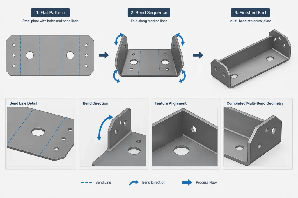
Multiple bends and bend sequence
Parts with multiple bends need more than an overall flat outline. Bend sequence can affect whether the piece can be positioned in the forming equipment and whether a completed leg interferes with a later bend. Opposing bends, narrow returns, closed shapes, and bends near wide connection plates deserve early fabricator input.
Each bend should be identifiable in the drawing or data exchanged with the shop. Bend labels can relate the flat pattern to the finished view and help prevent a bend from being made in the wrong direction. A simple formed-part isometric showing “up” and “down” relationships can resolve orientation more reliably than text alone.
Common detailing mistakes
- Treating a rounded bend as a theoretical sharp corner without defining the dimension basis.
- Adding finished leg dimensions and labeling the result as the flat length.
- Using a software-default bend rule without fabricator coordination.
- Calling out an angle without clarifying whether it is the bend angle or finished included angle.
- Locating holes only from flat blank edges when finished fit controls their position.
- Showing bend lines without arrows, labels, or a finished orientation view.
- Providing both flat and finished dimensions as controlling when small differences exist between them.
- Ignoring tooling access and bend sequence on plates with multiple returns.
- Assuming that a mirrored part can use the same bend directions and hole orientation.
A practical review checklist
Before issuing a bent plate detail, verify that the finished shape is fully defined, the dimension references are identifiable, and the bend radius responsibility is understood. Confirm that connection-critical features are dimensioned from finished datums, not merely from an automatically generated blank. Review bend direction, handedness, feature proximity, and the relationship between the flat and formed views.
Most importantly, distinguish design intent from fabrication development. The design drawing should clearly establish what the completed plate must fit and connect to. The fabricator’s forming knowledge, tooling, and verified bend data should inform how that geometry is produced from a flat plate. Keeping those roles clear results in cleaner CAD files, fewer conflicting dimensions, and more dependable shop information.