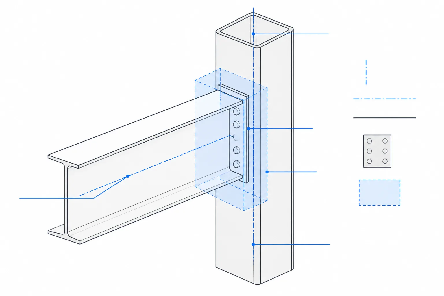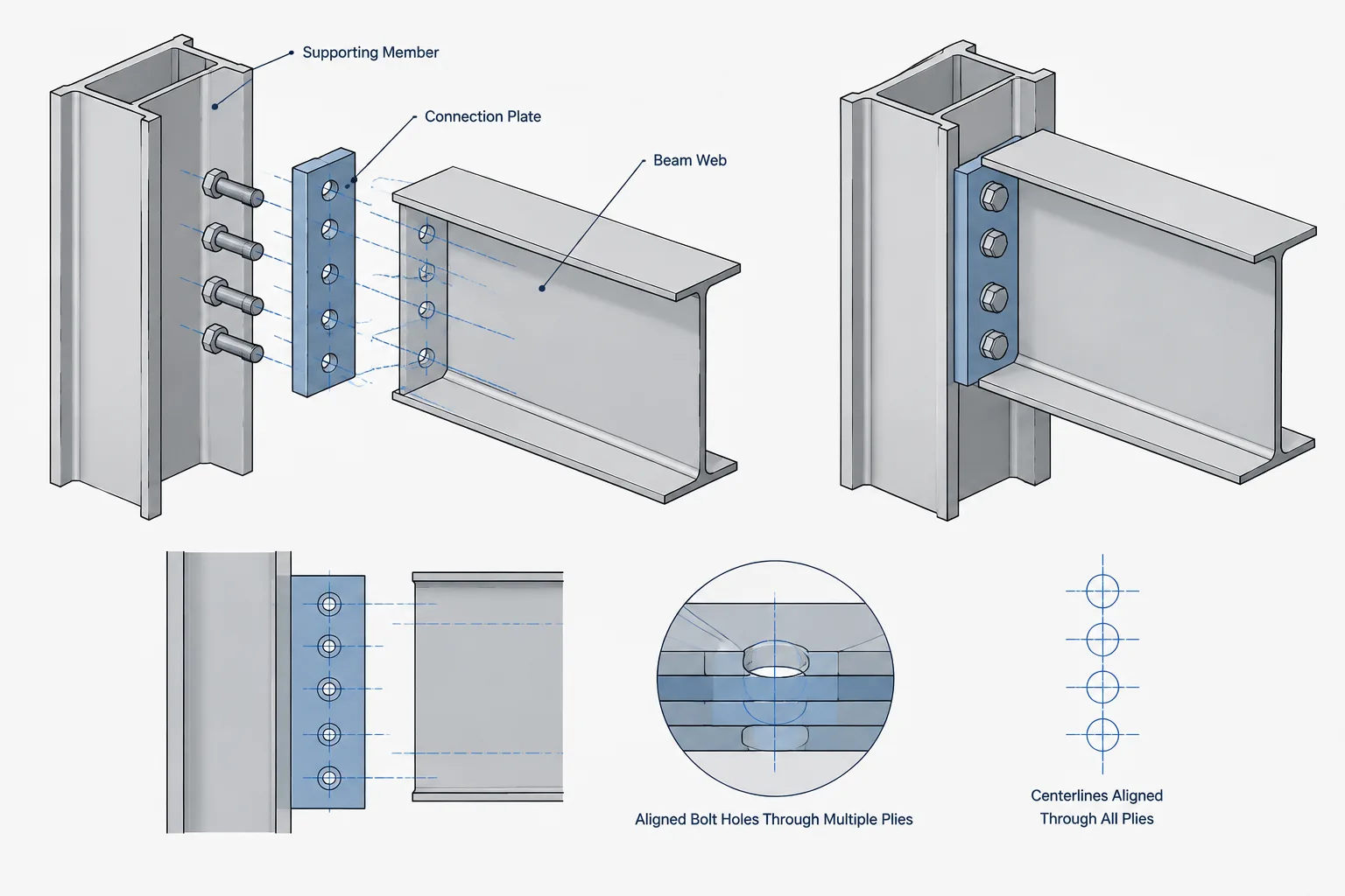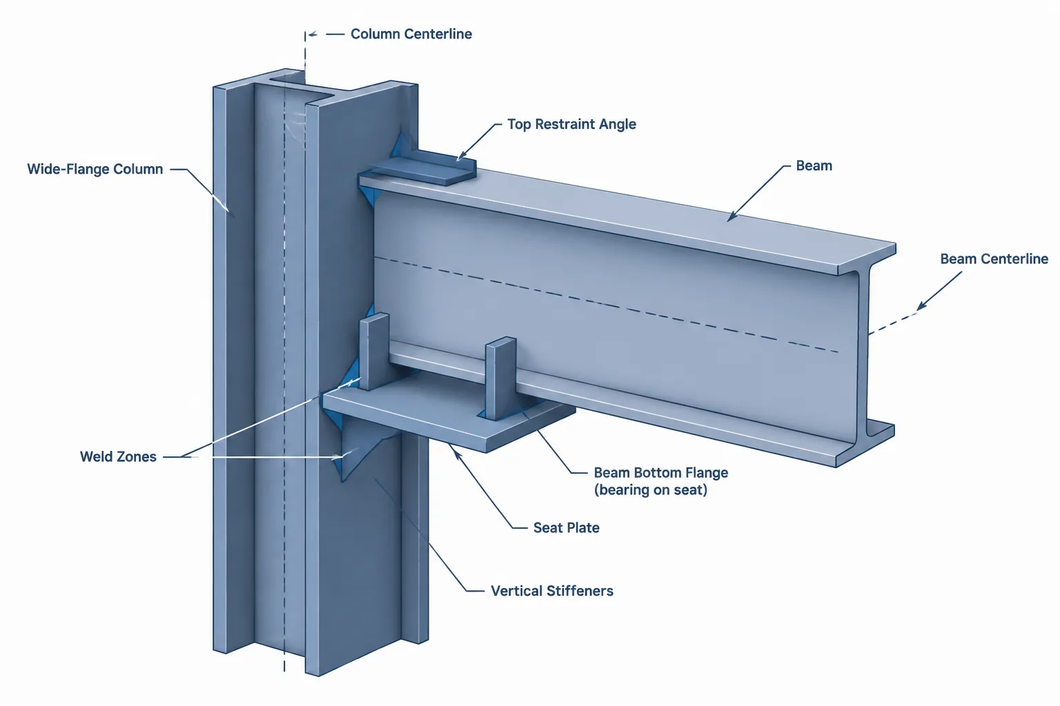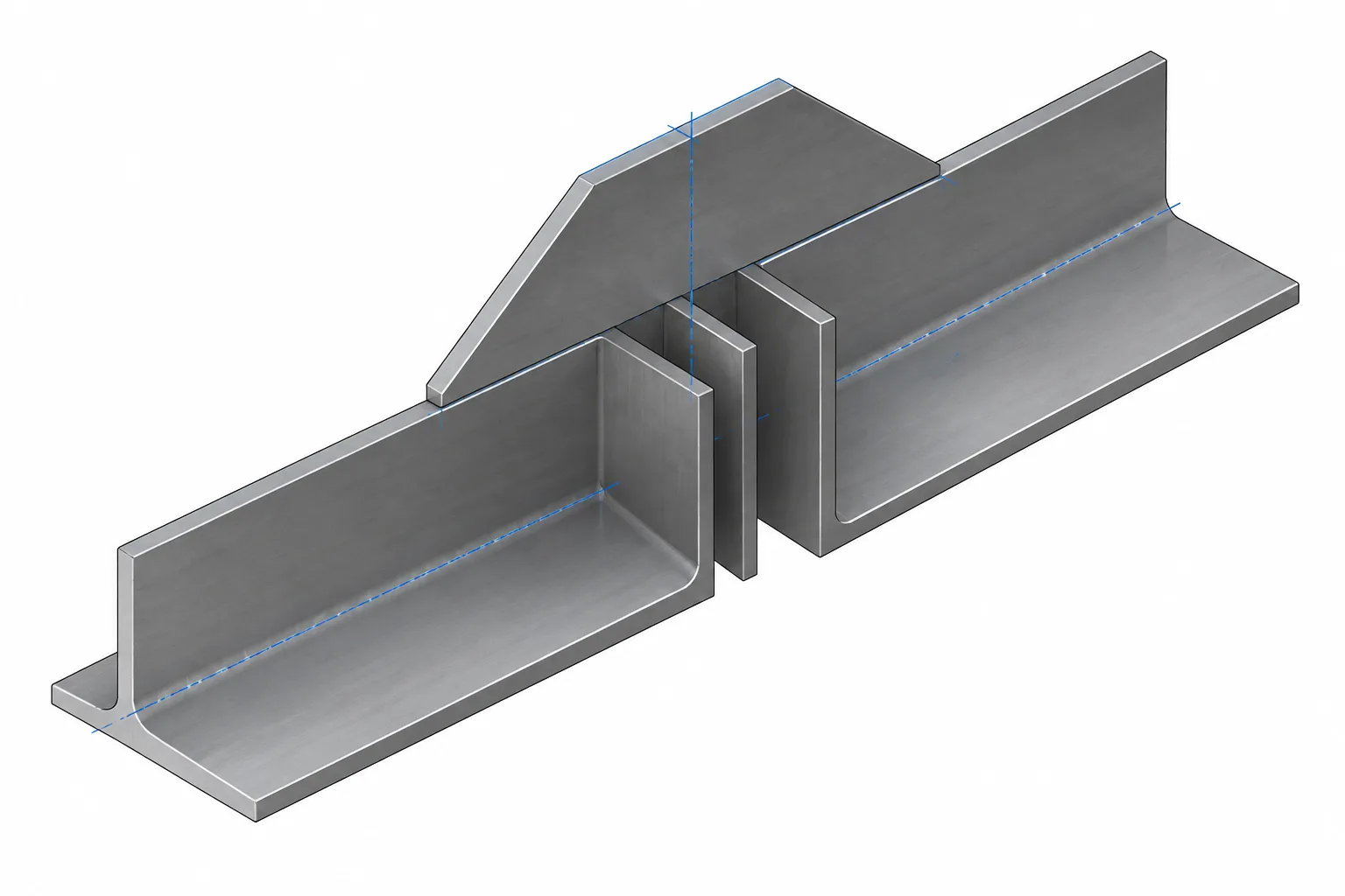
HSS branch connections occur when one hollow structural section frames into the wall of another. Common examples include truss webs meeting chords, braces connecting to columns, and secondary members joining larger HSS members. Although the finished joint may look simple, its detailing depends on several different geometric references: member centerlines, outside faces, theoretical work points, actual cut edges, and weld boundaries.
A reliable drawing or model must communicate more than the branch angle. It must establish where the members theoretically intersect, how the branch end is shaped, which member remains continuous, and whether the fabricator has enough access to cut, fit, and weld the joint. Structural design requirements still govern the connection, but clear geometry allows those requirements to be translated into usable shop information.
Chord, Branch, and Joint Terminology
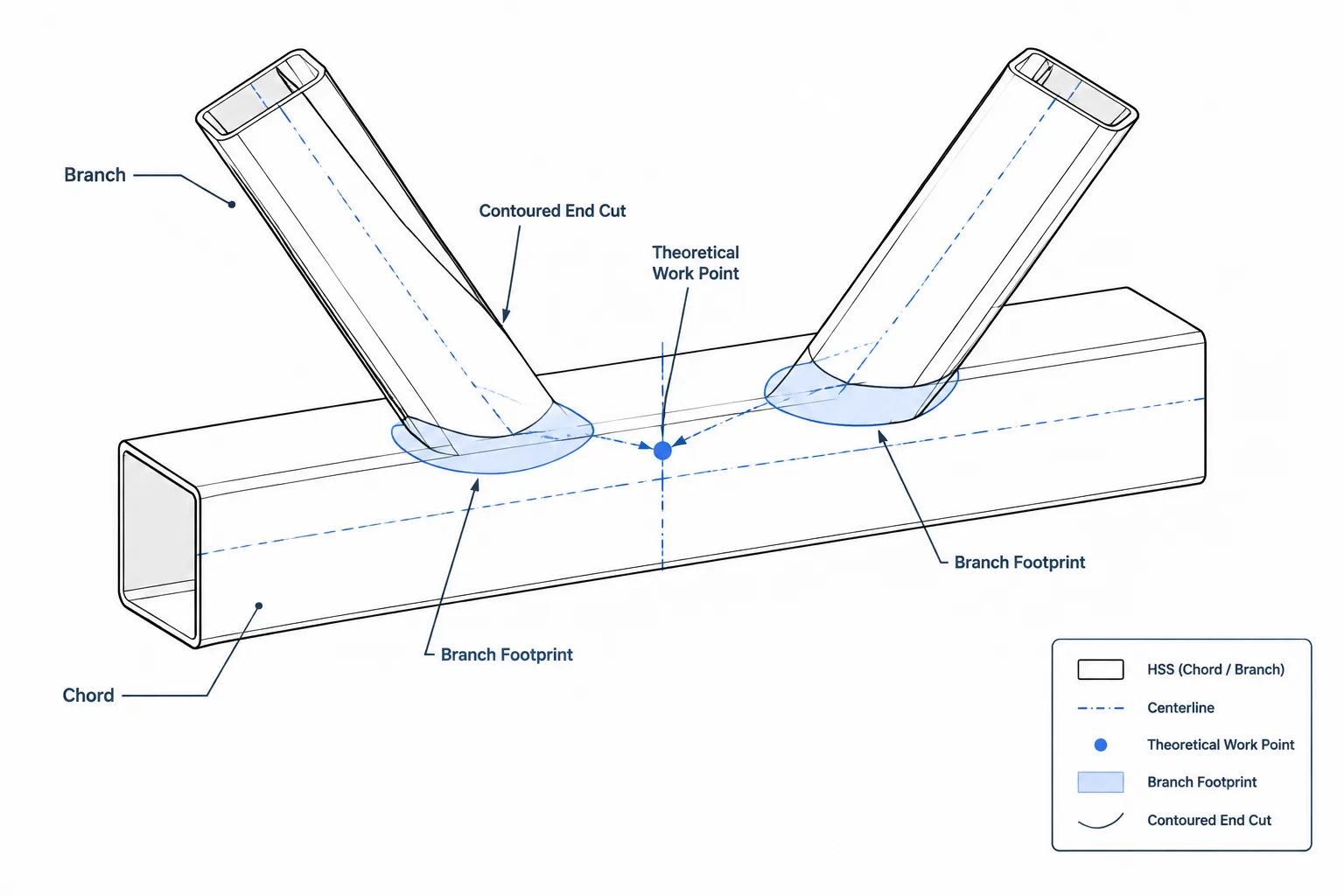
The chord is the member that generally remains continuous through the joint. The branch is the incoming HSS member terminated at the chord. In a truss, the chord may be horizontal or sloped, while the branches may be vertical, diagonal, or arranged in pairs.
The words describe the connection relationship, not necessarily the relative member sizes. A branch is often smaller than its chord, but size alone should not be used to identify the continuous member.
- Branch centerline: The longitudinal reference axis of the incoming member.
- Chord centerline: The longitudinal axis of the continuous member.
- Work point: A theoretical intersection used to control framing geometry.
- Branch footprint: The area or perimeter projected onto the chord surface by the incoming member.
- Cut profile: The actual three-dimensional edge produced at the end of the branch.
- Connection zone: The chord region affected by the branch, welds, reinforcement, and nearby attachments.
The Work Point Does Not Define the Entire Cut
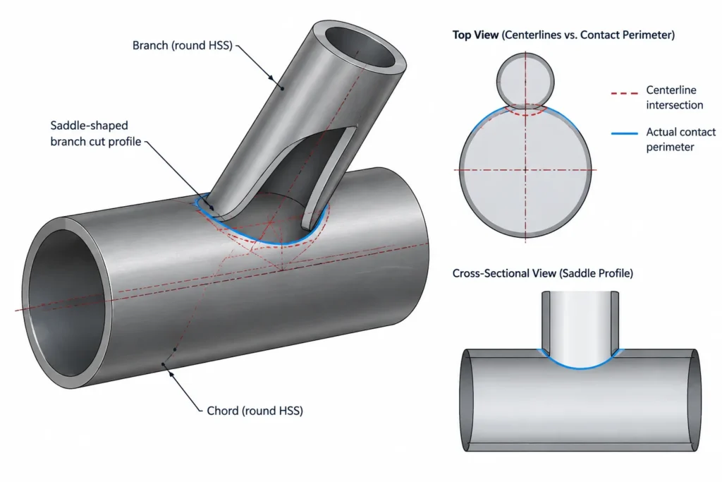
Structural framing is commonly laid out from member centerlines. Extending the branch and chord centerlines until they intersect creates a convenient work point for analysis and overall geometry. That point does not, by itself, establish the branch cut.
The cut depends on the actual outside surfaces of both members. A branch centerline passing through a work point can produce different end geometry when the chord size, branch size, section type, or orientation changes. Replacing one rectangular HSS with another may therefore alter the cut profile even if the framing centerlines remain unchanged.
Detailers should distinguish between the dimension that controls the theoretical member layout and the dimensions or model geometry that control fabrication. When a drawing gives only a centerline angle and work-point location, the fabricator may still need information about section rotation, chord face, end treatment, and fitting intent.
How Section Type Changes the Intersection
Rectangular or Square HSS into a Flat Chord Face
A rectangular or square branch framing squarely into a flat chord face may appear to require a simple planar cut. That can be true when the branch axis is normal to the face and its section is not rotated. Once the branch becomes sloped or skewed, the apparent straight cut develops different edge locations around the branch perimeter.
Corner radii also matter. HSS is not made from four perfectly sharp outside corners. A simplified CAD model may be adequate for general arrangement, but fabrication geometry should not assume sharp corners where the real product has curved regions.
Round HSS Intersections
A round branch meeting a round chord typically requires a contoured or saddle-type end profile. The profile varies continuously around the branch circumference and changes with the diameters and intersection angle. A flat end cut will not reproduce that contact condition.
Round-to-rectangular and rectangular-to-round joints combine curved and planar geometry. These connections deserve explicit model review because a familiar-looking elevation can conceal substantial variation around the joint.
Rotated Rectangular HSS
If a rectangular branch is rotated about its own longitudinal axis, its faces and corners meet the chord differently. The centerline may remain unchanged while the cut, branch footprint, weld path, and overall clearance all change. Section rotation must therefore be treated as controlling geometry rather than a graphical preference.
Gap, Abutting, and Overlap Arrangements
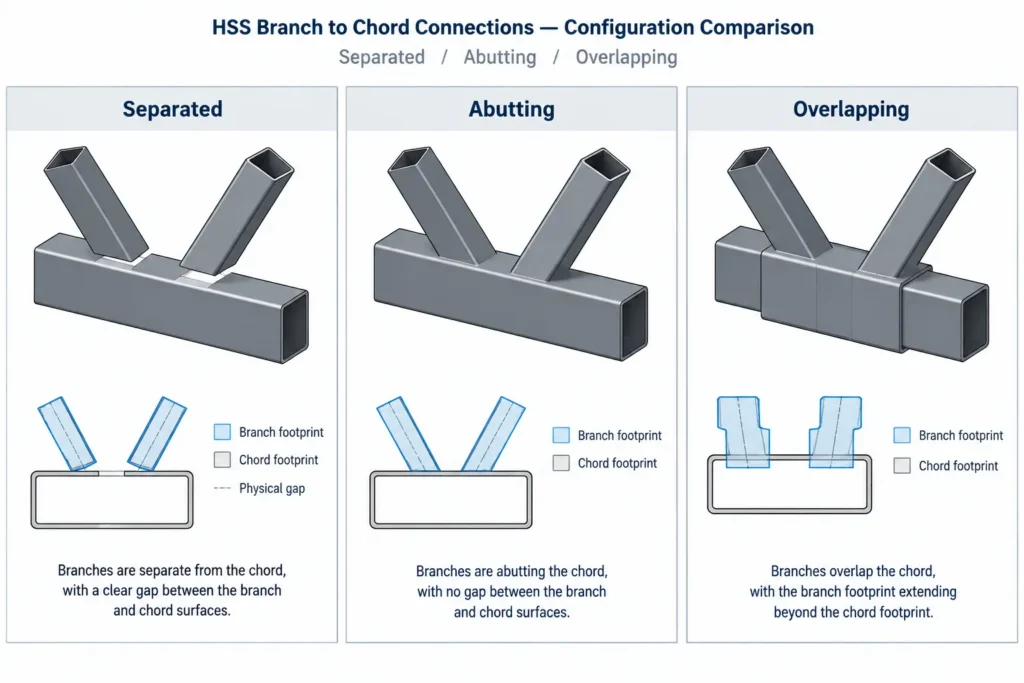
When multiple branches meet the same chord region, their relationship must be identified clearly. Three broad arrangements are useful for detailing discussions.
| Arrangement | Geometric condition | Primary detailing concern |
|---|---|---|
| Separated branches | Distinct branch footprints with chord surface between them | Clear gap definition, weld access, and chord connection-zone spacing |
| Abutting branches | Branch ends or footprints meet near a shared location | Fit sequence, intersecting weld paths, and ambiguous cut boundaries |
| Overlapping branches | One branch physically overlaps or is fitted against another near the chord | Which branch is continuous, cutting sequence, hidden contact, and weld access |
A centerline dimension between branches does not necessarily define the clear surface gap. For sloped members, the closest points may occur at corners or along projected footprints rather than along the centerline plane. The model and drawing should make clear whether a stated gap is measured between centerlines, theoretical intersection lines, branch faces, or actual cut edges.
For overlap arrangements, identify which branch is placed first and which member is cut to fit. Without that information, two visually similar drawings can imply different parts and fabrication sequences.
Branch Cut Profiles and Fabrication Data
A branch end may be represented at several levels of detail. General arrangement drawings may show only the member envelope and approximate intersection. Shop information may require an exact profile, developed cut path, machine data, or a verified fitting template.
Before generating fabrication geometry, confirm:
- The correct HSS outside dimensions and wall designation are assigned.
- The chord and branch axes use the intended work points.
- The rectangular section is rotated to the correct face orientation.
- The model accounts for relevant outside corner geometry.
- The intended fitting condition is understood rather than inferred from a visual clash.
- Any root opening, end preparation, or weld-related modification comes from approved connection information.
- The cut is associated with the correct piece mark and member end.
Automated intersection tools can create plausible geometry from incorrect inputs. A successful Boolean cut only proves that two modeled solids intersect; it does not prove that the member orientation, work point, weld condition, or connection intent is correct.
Weld Access and Visibility Around the Joint
The entire branch perimeter should be reviewed, not just the visible edges in elevation. The far side of a branch may be close to another branch, plate, chord corner, or adjacent framing member. A weld shown schematically as continuous around the branch can still present access and sequencing questions.
Useful checks include whether the welding process can reach the far side, whether an adjacent branch blocks the required approach, and whether the joint can be inspected as intended. On tightly grouped truss joints, assembly sequence may determine whether a weld remains accessible at all.
Drawings should avoid implying a weld path that disappears behind another member without explaining the joint arrangement. Sections, enlarged details, or a clear three-dimensional view can reveal conditions that are ambiguous in a single elevation.
Chord Faces, Seams, and Adjacent Features
For rectangular HSS chords, identify the face receiving the branch. Top, bottom, and side faces may have different relationships to floor framing, gusset plates, internal reinforcement, or other attachments. A section rotation error can move every branch to the wrong face even while the centerline model appears aligned.
The HSS manufacturing seam may also be relevant to connection planning and fabrication coordination. Its exact location should not be assumed solely from a generic CAD block. Where seam orientation affects a connection decision, the drawing and procurement workflow should address it explicitly.
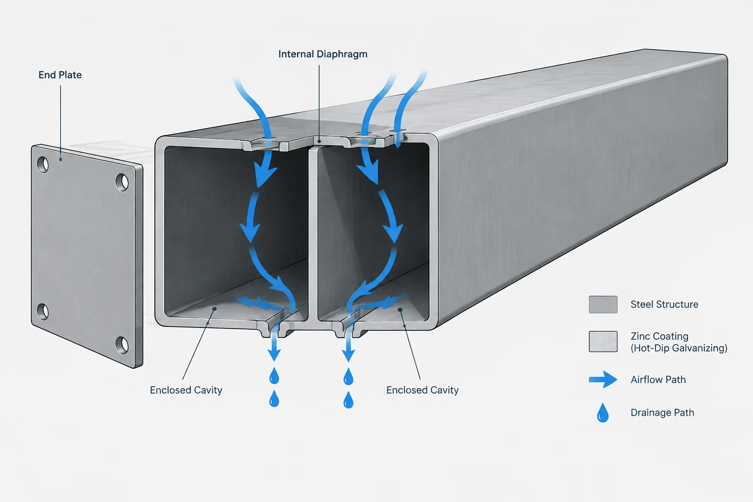
Other features within the connection zone can include cap plates, diaphragms, through-plates, slots, vent paths, drain openings, and concealed attachments. These must be coordinated as a group rather than detailed as independent items occupying the same HSS volume.
A Practical CAD and Drawing Workflow
- Lay out theoretical geometry. Establish chord and branch centerlines, work points, slopes, and plan angles.
- Assign real section orientation. Confirm which rectangular HSS face is up or connected and whether any member is rotated.
- Create the member envelopes. Use suitable section geometry for the required level of development.
- Generate branch intersections. Produce cut profiles from the verified member surfaces, not from a two-dimensional appearance.
- Review gaps and overlaps. Inspect true three-dimensional clearances between branch edges and neighboring parts.
- Add connection information. Apply approved weld, preparation, reinforcement, and access requirements without allowing the CAD tool to invent them.
- Check fabrication sequence. Determine whether all cuts and welds remain possible after adjacent parts are installed.
- Create clear views. Use elevations, sections, end views, or isometric details to show conditions that centerlines cannot communicate.
- Recheck after member changes. A section substitution can change footprints, cuts, gaps, weld lengths, and access even when work points stay fixed.
Final Coordination Checklist
- Is the continuous chord clearly distinguished from each terminated branch?
- Are work points and member centerlines consistent between plans, elevations, and the model?
- Is the connected chord face unambiguous?
- Does each branch have the correct section rotation?
- Are stated gaps tied to clearly defined physical references?
- For overlaps, is the continuous or first-installed branch identified?
- Do cut profiles reflect actual member surfaces rather than sharp-corner simplifications?
- Can the required welds be placed and accessed around the joint?
- Have nearby plates, branches, seams, openings, and internal components been coordinated?
- Will piece marks and fabrication exports preserve the correct end and orientation?
Good HSS branch detailing connects theoretical framing geometry to physical fabrication. Centerlines and work points establish the structural layout, while chord faces, branch footprints, cut profiles, and weld access define the joint that the shop must actually build. Keeping those reference systems distinct—and checking them together—reduces ambiguous cuts, inaccessible welds, and unexpected fit-up conflicts.