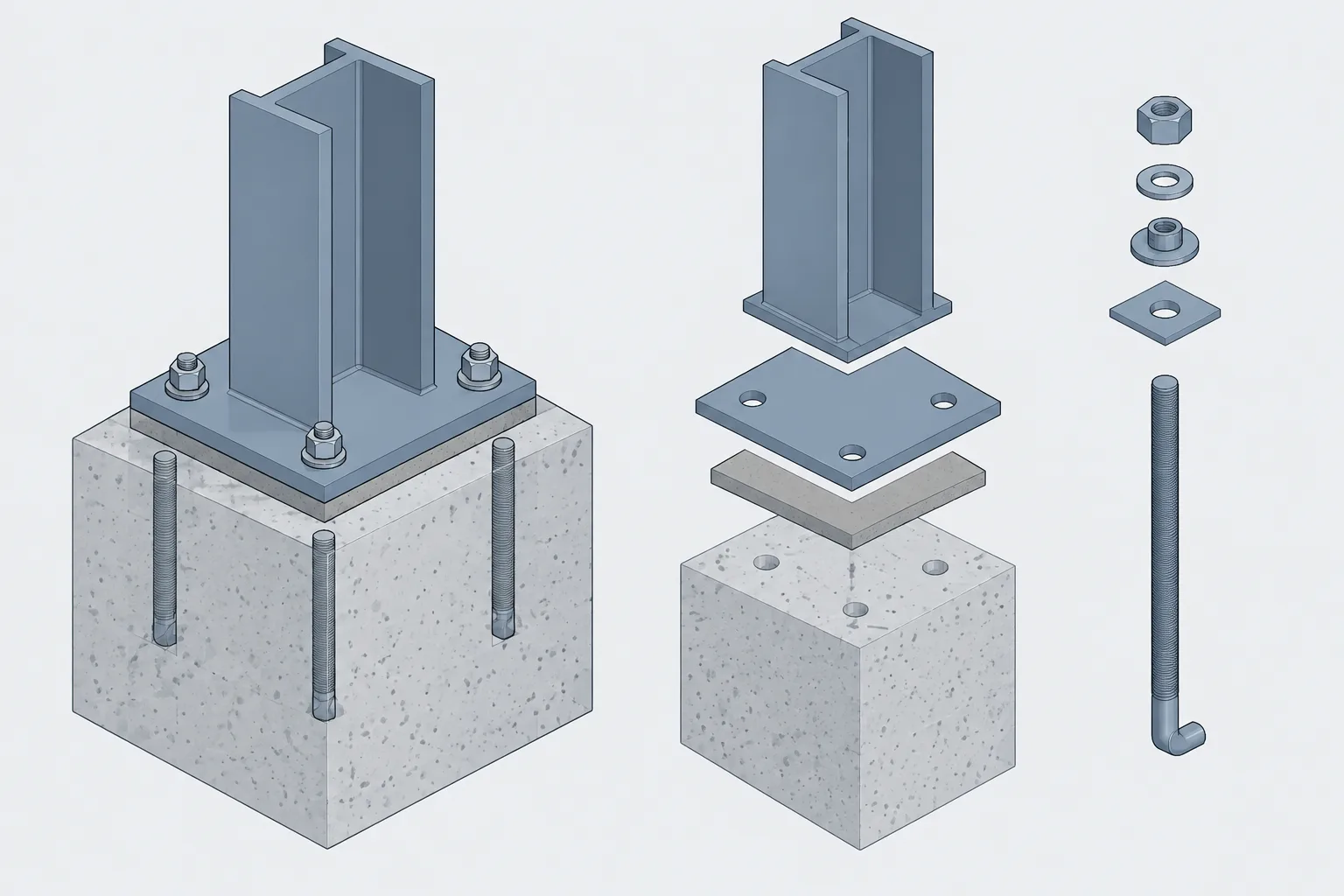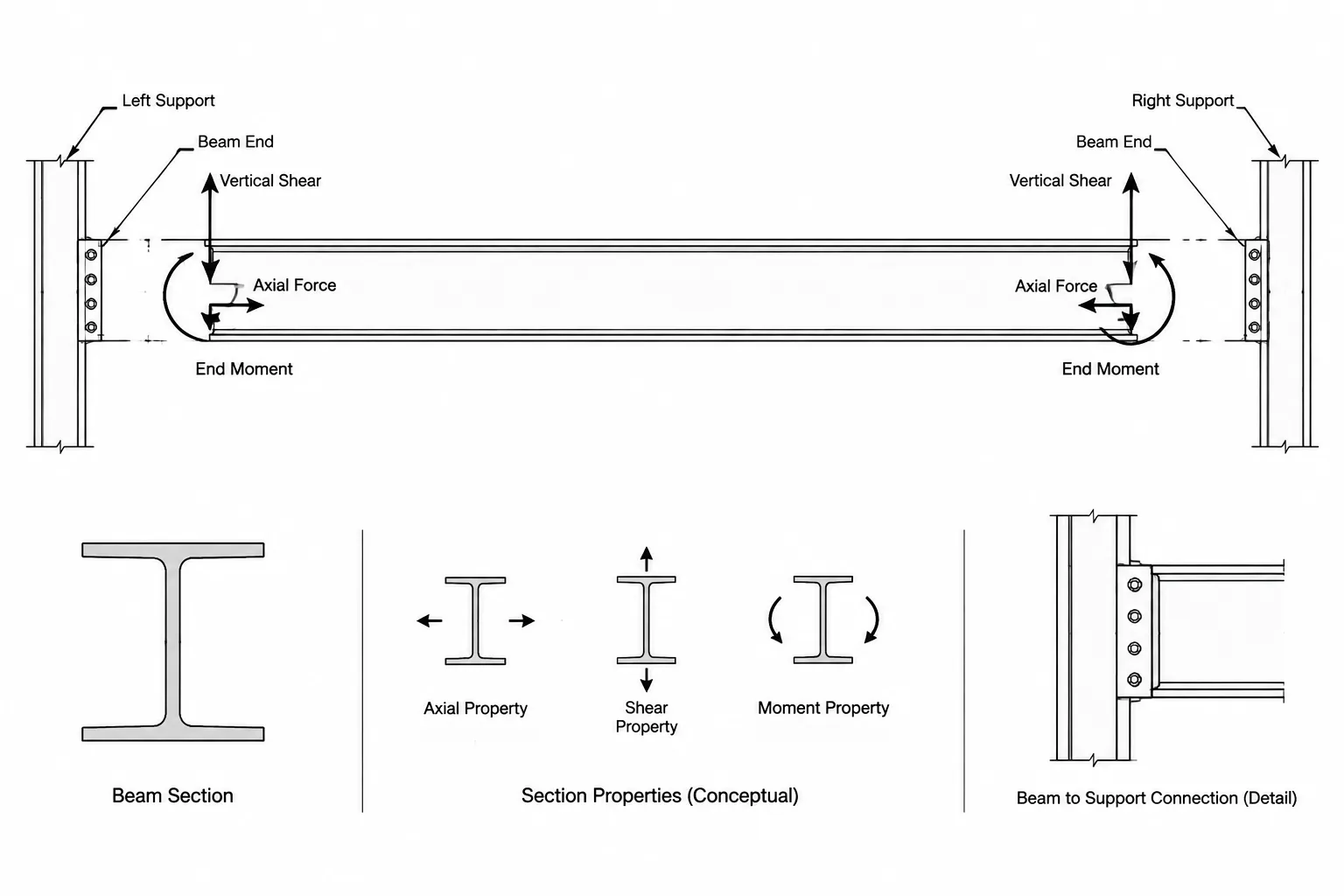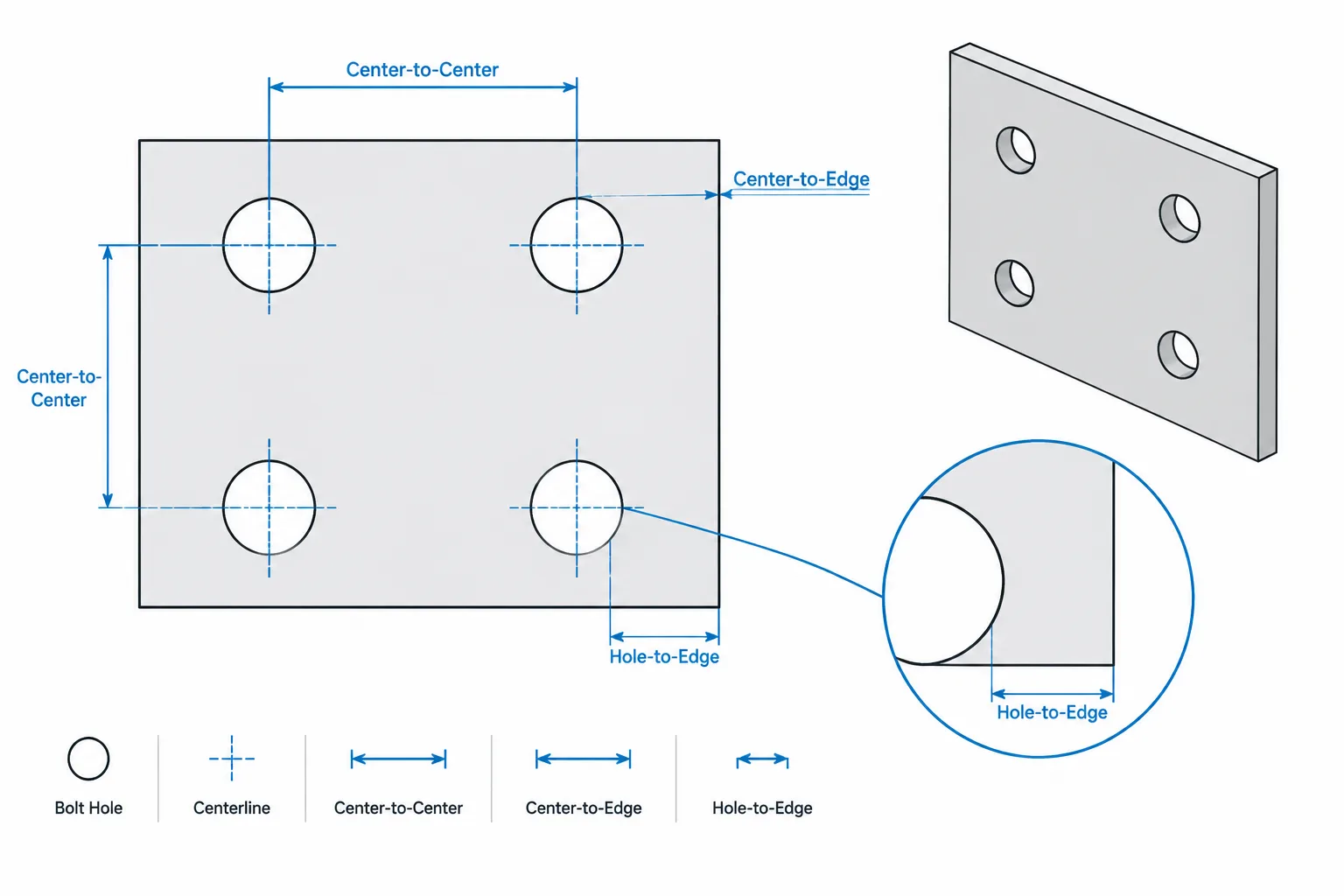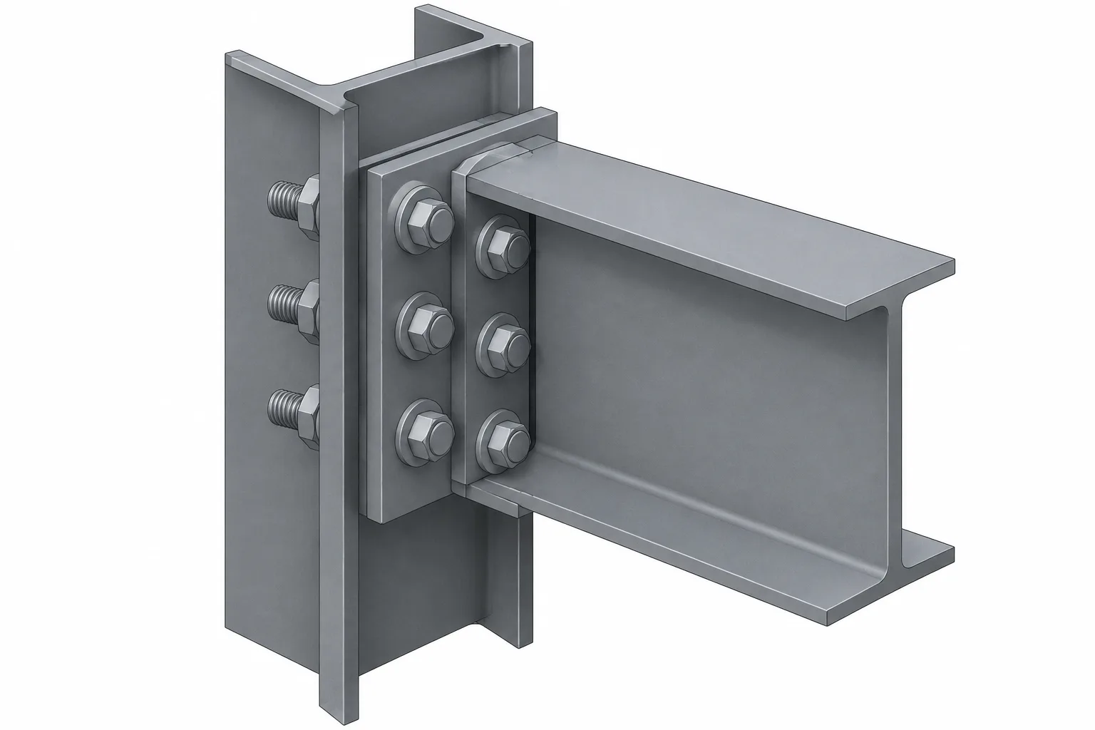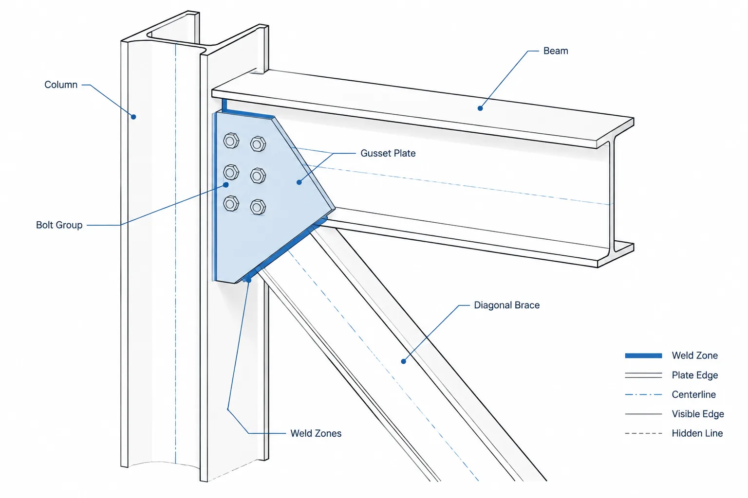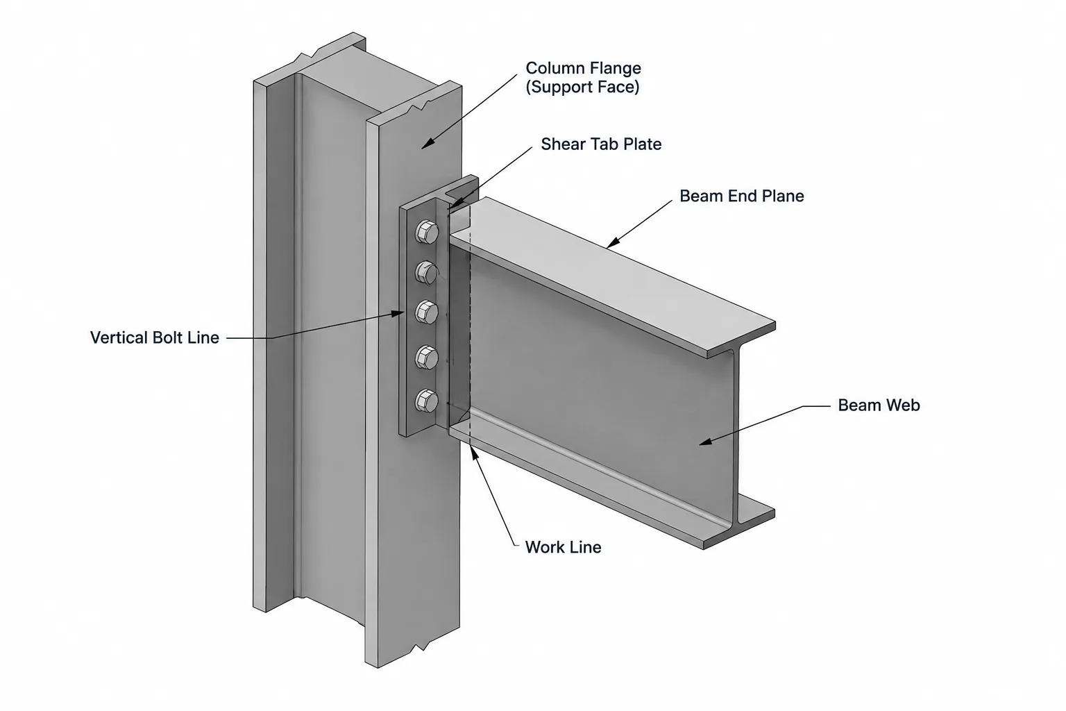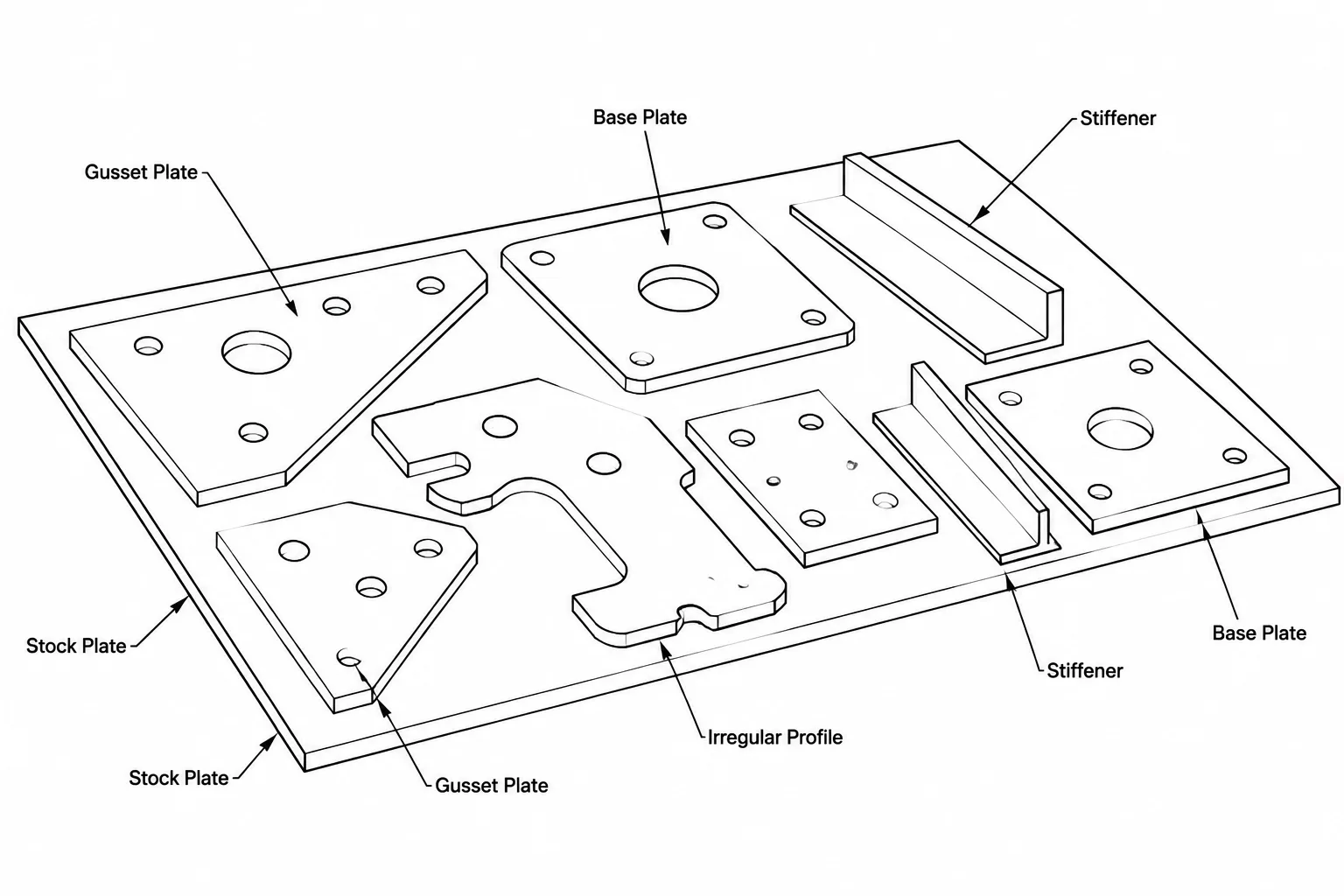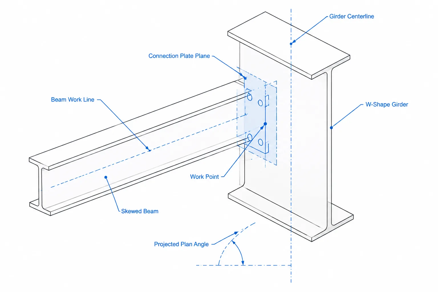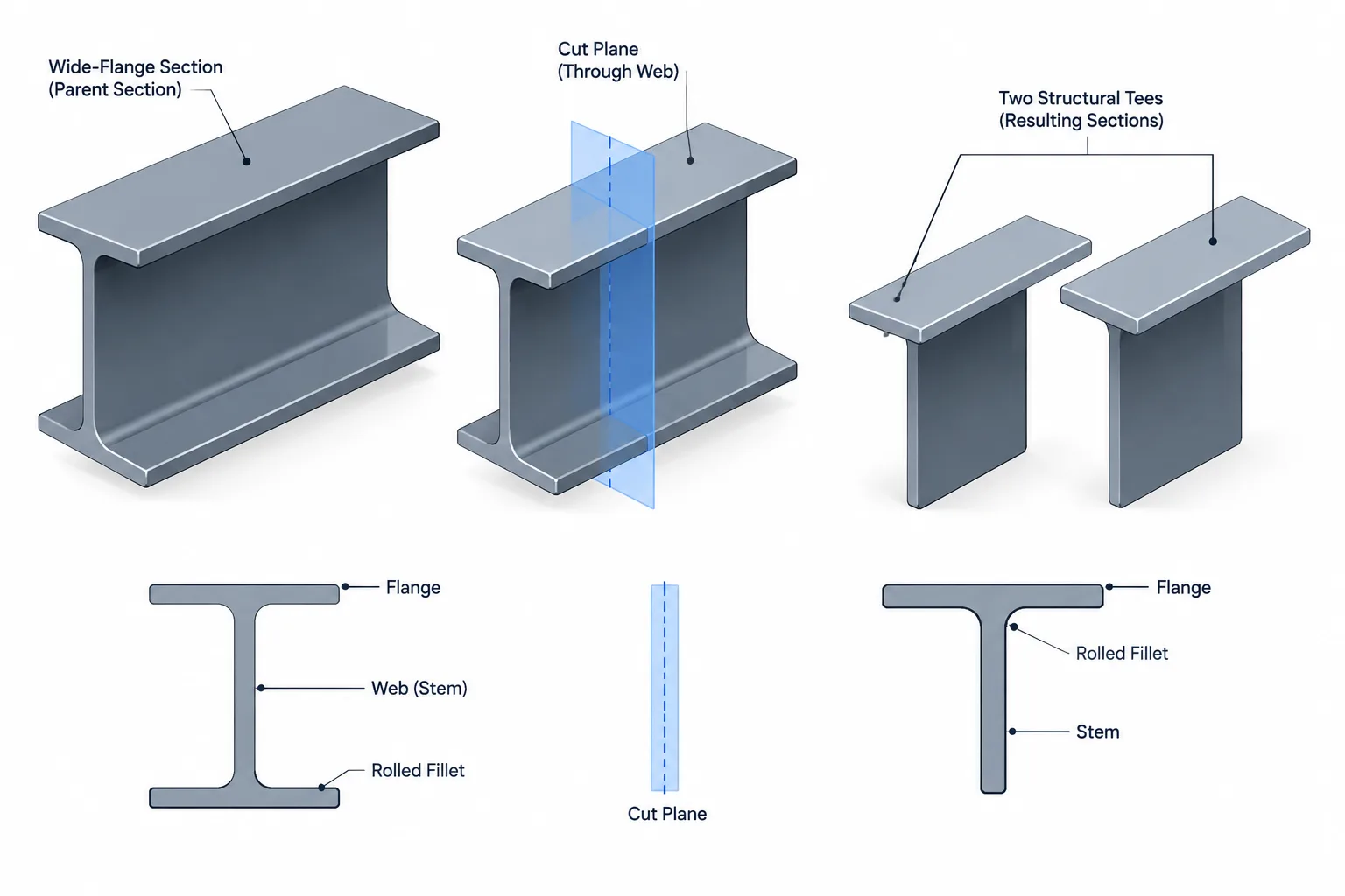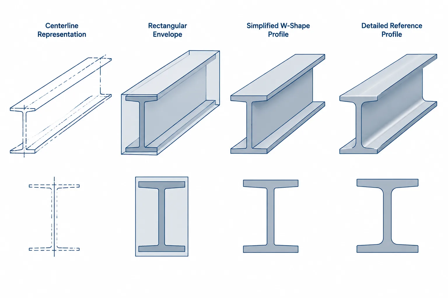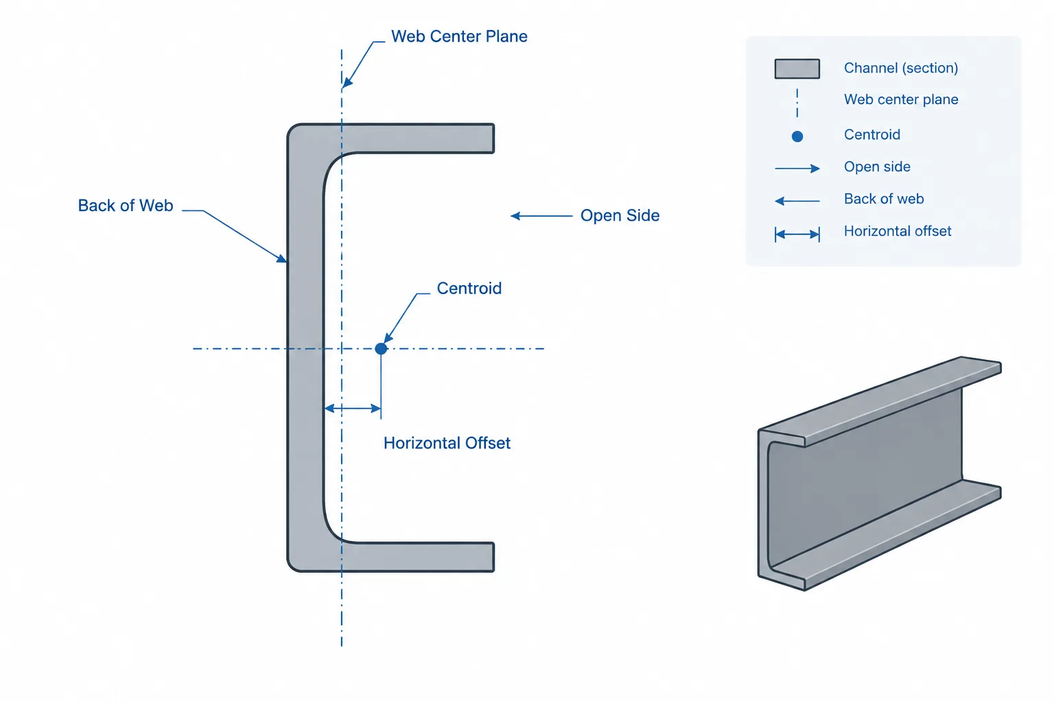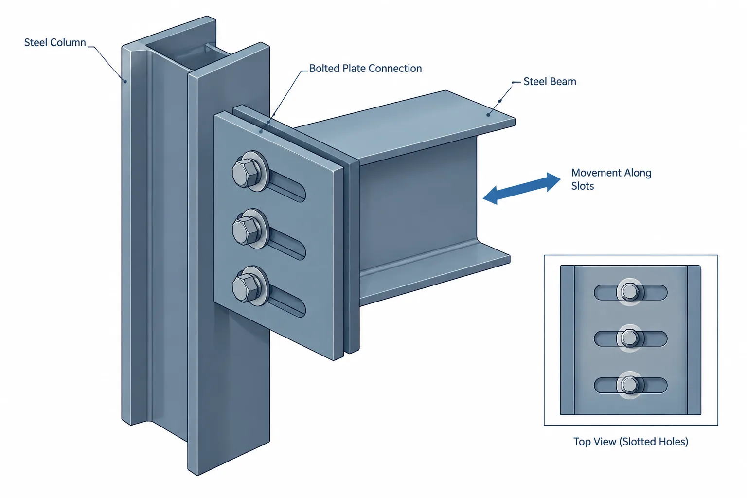
Slotted bolt holes are often shown where a structural steel connection must accommodate erection adjustment, thermal movement, differential deflection, or another defined displacement. The slot may look simple in a detail, but its behavior depends on much more than the outline of an elongated hole.
A workable detail must coordinate the direction of movement, the surfaces that may slide, the location of the bolt within the slot, the method of restraint, and the hardware covering the opening. Designers and detailers must also distinguish between a slot intended only for fit-up and one intended to remain capable of movement after installation.
This guide focuses on the drawing and coordination issues surrounding slotted bolt holes. It does not establish connection capacity, permitted hole dimensions, installation procedures, or code compliance. Those requirements must come from the governing design documents, specifications, and applicable standards.
A Slot Provides a Geometric Path, Not a Complete Movement Detail
An elongated hole provides potential travel parallel to its long axis. It does not, by itself, guarantee that the connected parts can move. Friction, bolt pretension, bearing, welds, surface coatings, interference with adjacent components, or another restrained connection may prevent the intended displacement.
When reviewing a slotted connection, separate three questions:
- What movement is expected? Identify its direction, source, and approximate range as defined by the project engineer.
- Which part is intended to move? Determine whether the beam, plate, angle, clip, support, or attached construction moves relative to another part.
- What prevents unwanted movement? A connection may permit translation along one axis while restraining translation or rotation in other directions.
The complete load path and restraint system must be considered. Adding slots to one plate does not create a functional movement joint if bolts in another connection, welded attachments, decking, cladding, piping, or finishes lock the assembly in place.
Slot Direction Must Match the Intended Relative Movement
The long axis of a slot should be read as a direction in the plane of the connected material. It is therefore important to show the slot in a view that reveals its true orientation. A plan view may clearly show longitudinal travel in a horizontal plate, while an elevation or section may be required for a slot in a vertical plate.
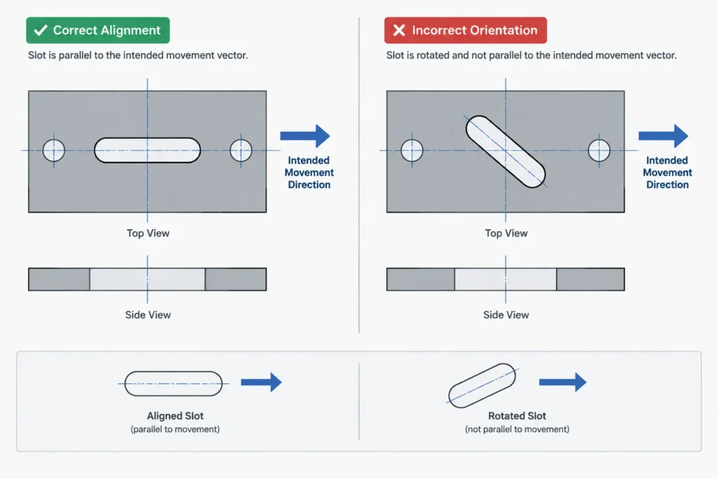
For sloped or skewed members, labels such as horizontal, vertical, or longitudinal can become ambiguous. A more reliable drawing relates the slot to a defined datum, member work line, plate edge, or local member axis. If the slot follows a sloped member, the detail should make clear whether its direction is parallel to the member, parallel to the supporting surface, or projected into a drawing view.
A projected slot can appear shorter or rotated when it is not parallel to the view plane. Detailers should model or construct the true slot geometry in the plate plane before creating orthographic views. The shop drawing should not rely on a visually stretched symbol that has no clear fabrication orientation.
Slots do not accommodate meaningful movement across their width
Travel is primarily available along the slot length. Movement perpendicular to that direction quickly brings the bolt shank toward the side of the hole. If movement has components in more than one direction, the connection concept may require a different arrangement rather than simply rotating or widening a slot without engineering review.
Fit-Up Slots and Active Movement Slots Are Different
A fit-up slot provides installation tolerance so parts can be aligned during erection. Once the connection is positioned and completed, it may be intended to act as a restrained connection. An active movement slot is intended to preserve some capacity for relative movement in service.
This difference affects the entire detail, including bolt installation, surface condition, washer arrangement, and the position of the bolt when the connection is finalized. A note that merely says “slot” does not communicate the intended function.
| Coordination issue | Fit-up or adjustment slot | Active movement slot |
|---|---|---|
| Primary purpose | Assist alignment and assembly | Accommodate defined service movement |
| Final restraint | May become fully restrained after installation | Must retain the intended movement mechanism |
| Bolt position | May be established by actual fit-up | Usually coordinated with the expected direction and range of travel |
| Interface behavior | Specified connection behavior governs after tightening | Sliding or another deliberate mechanism must remain possible |
| Drawing information | Slot geometry and erection intent | Movement direction, initial position, restraint concept, and installation condition |
The engineer responsible for the connection should define which condition applies. A fabricator or detailer should not infer that a slot is free-sliding simply because it is elongated.
Bolt Position Within the Slot Matters
The bolt may be shown at the center of a slot, but centered placement is not automatically correct. The required initial location depends on when the steel is erected, the expected direction of future movement, and the reference condition used by the design.
For example, a component expected to expand primarily in one direction may need more available travel on one side of the bolt than the other. A centered bolt provides travel in both directions, while an intentionally offset bolt reserves more slot length for movement toward one end. The required position should be communicated rather than left to visual interpretation.
Useful drawing information may include:
- The intended bolt position at installation
- The direction of anticipated movement
- The condition associated with the initial position
- Whether field adjustment is required before final tightening
- Which component contains the slot
- Whether similar-looking connections have different installation conditions
Do not dimension the bolt only from the end of the slot unless that relationship is intended to control installation. Fabrication dimensions should define the slot relative to stable plate datums, while erection instructions should separately describe the required assembled position.
Washers and Cover Plates Require Deliberate Coordination
Hardware at a slotted hole must be coordinated with the hole opening and the intended connection behavior. A conventional washer that appears adequate around a round hole may not cover an elongated opening in every bolt position. The applicable design and specification must establish whether a different washer arrangement, plate washer, or other detail is required.
Coverage should be checked at the extreme permitted bolt positions, not only with the bolt centered. The detailer should also check whether the washer or cover plate collides with a weld, rolled-shape fillet, plate bend, stiffener, HSS corner radius, or adjacent bolt.
A welded cover plate can also change behavior. If a plate washer is welded to both connected components, or if welding bridges the intended sliding interface, the detail may become restrained. Welding instructions must clearly identify what is attached to what.
Identify the Sliding Interface
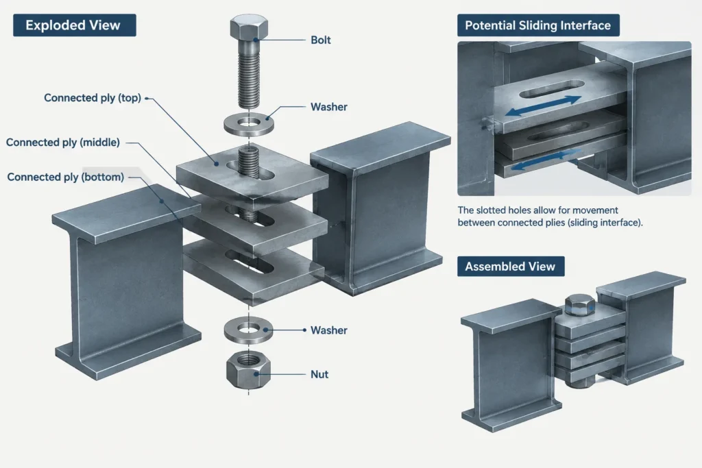
A movement connection needs a clearly understood interface between the parts. If a support angle is welded to a column and bolted through slots to a beam attachment, the relative movement may occur between the angle and the attachment. In another arrangement, the slot may be in a plate while a separate bearing surface carries gravity load.
Draw the connection in section when an elevation does not explain the stack. The section should distinguish the connected plies, washers, bolt head and nut sides, gaps where applicable, and nearby surfaces that could bind. It should also reveal whether projecting bolt ends or hardware can strike another part as movement occurs.
Surface treatment requires project-specific review. Paint, galvanizing, debris, burrs, sealants, and field-applied coatings can affect the interface or reduce clearance. Detailers should flag these conditions for specification and fabrication coordination rather than assuming a particular friction or sliding performance.
Fixed Points and Sliding Points Must Work as a System
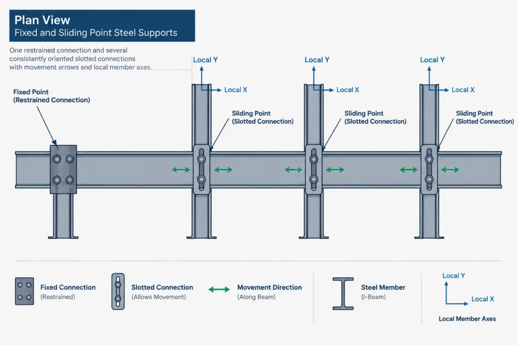
Many movement arrangements use a fixed point to establish position and one or more sliding points to accommodate displacement. Without a defined fixed point, the supported element may drift or have an uncertain reference location. With too many fixed points, the system may be over-restrained.
The relevant points may occur in separate connections or even at opposite ends of a member. Reviewing a single detail in isolation can therefore be misleading. Plans, elevations, and connection schedules should use consistent terminology to identify fixed and movable locations.
A useful coordination review asks:
- Where is the assembly positively located?
- Which connections permit movement?
- Are all slots aligned with the same intended movement path?
- Does another framing element unintentionally brace or lock the moving component?
- Can attached architectural or mechanical work tolerate the same movement?
- Is the erection sequence compatible with the specified initial bolt position?
Recommended CAD and Shop-Drawing Workflow
- Establish the movement vector. Represent the required direction in the plate plane using a construction line or local axis.
- Model the true hole geometry. Create the slot in the actual part rather than drawing a symbolic outline only in a sheet view.
- Locate it from fabrication datums. Dimension the slot centerline or end geometry from stable edges, centerlines, or work points.
- Show the assembled bolt position separately. Do not confuse the fabricated hole location with the required field position of the bolt.
- Check all movement extremes. Review washer coverage, edge clearance, bolt access, clashes, and remaining travel at each limiting position.
- Create a section through the ply stack. Confirm which surfaces contact, which may slide, and where hardware is placed.
- Coordinate notes and symbols. The model, detail, connection schedule, and erection notes should describe the same intent.
- Request clarification when behavior is undefined. Do not choose active-sliding behavior, tightening requirements, or installation position based only on a generic slot symbol.
Common Detailing Failures
- Slot rotated in the wrong view: The drawn long axis follows the sheet rather than the actual movement direction.
- Bolt always shown centered: The graphic convention masks a required offset installation position.
- Washer checked only at center: Coverage or clearance fails when the bolt moves toward a slot end.
- Unidentified slotted ply: Shop personnel cannot tell which plate or angle receives the slot.
- Conflicting restraints: A weld, second bolt group, brace, deck attachment, or adjacent connection prevents movement.
- No fixed reference point: Multiple slotted connections leave the assembly location uncertain.
- Movement note without a true direction: Terms such as longitudinal or horizontal are unclear on skewed or sloped framing.
- Symbolic CAD geometry: A simplified slot representation does not match the actual part orientation or fabrication data.
Final Review Principle
A successful slotted connection communicates more than hole shape. It identifies what moves, where it moves, how far it is intended to move, what remains restrained, and how the connection is installed in its initial condition. Slot orientation, bolt position, hardware, interfaces, and adjacent construction must all support the same concept.
When those items are not defined by the contract documents, the correct detailing response is coordination—not assumption. The connection engineer, project engineer, fabricator, erector, and affected trades may each hold information needed to turn an elongated hole into a reliable movement detail.