Gusset plates connect braces and other structural members at locations where several centerlines, fastener groups, welds, and material edges must be coordinated. Although a finished gusset may look like a simple polygon, its geometry is usually the result of several overlapping requirements.
Effective gusset plate detailing begins with the structural work points and member axes—not with an arbitrary plate outline. The connection designer establishes the required plate thickness, connection forces, fastener or weld requirements, and applicable limit states. The detailer then translates that information into coordinated geometry that can be fabricated, assembled, erected, and inspected.
What Controls Gusset Plate Geometry?
A gusset plate outline is influenced by more than the members visible in one elevation. Common geometric controls include:
- brace, beam, and column work lines;
- the theoretical intersection of member centerlines;
- bolt-group locations and required connection lengths;
- welded attachment lengths and weld access;
- brace end cuts, setbacks, and end clearances;
- beam flanges, column flanges, webs, stiffeners, and other connection material;
- tool access for drilling, bolting, welding, and inspection;
- erection paths and temporary positioning needs;
- plate free-edge shape and corner treatment; and
- the structural behavior assumed by the connection design.
These controls should be resolved together. Moving a bolt group to improve edge clearance, for example, may change the brace setback, plate size, connection eccentricity, or access for another connection component.
Start with Work Points and Member Centerlines
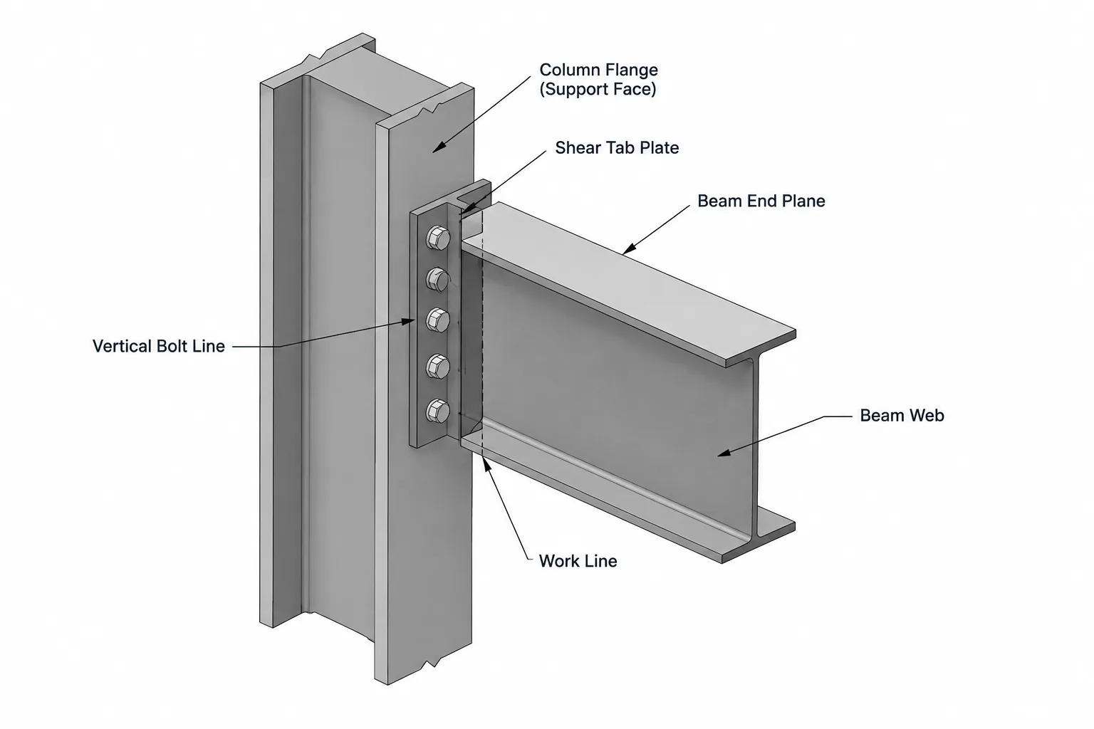
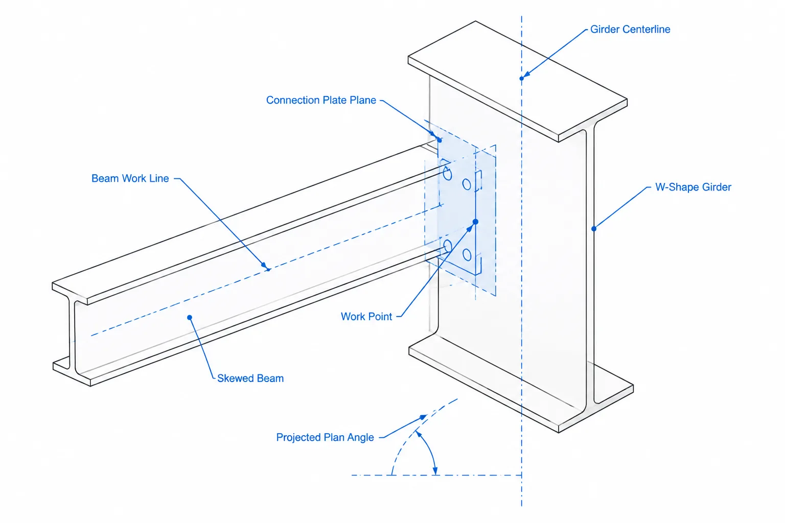
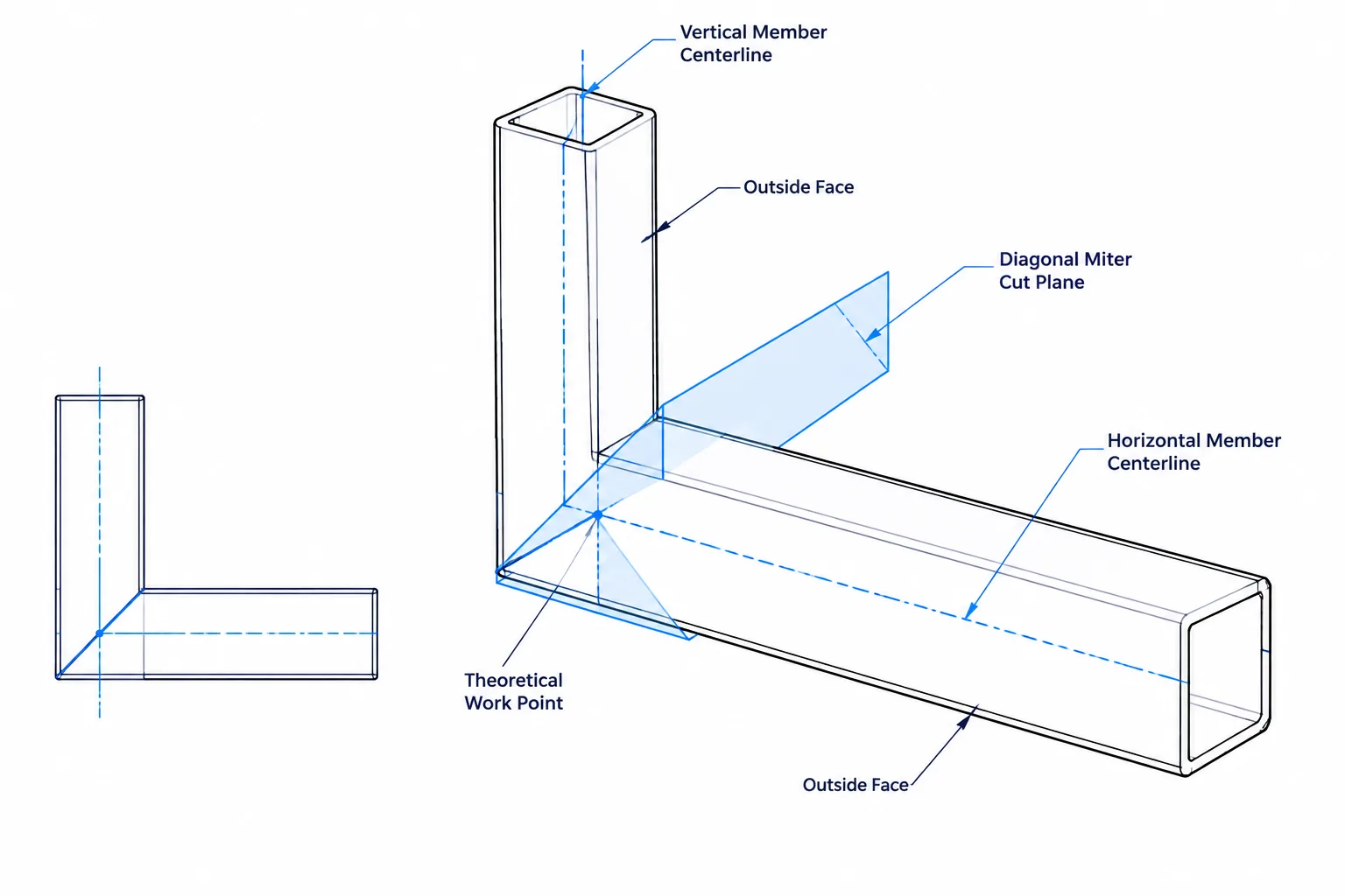
A brace is commonly laid out from a work line representing its structural axis. At a braced-frame joint, that line may intersect a beam centerline, column centerline, or another designated reference line. The intersection is the work point used to coordinate the framing geometry.
The work point is not necessarily a physical point on the gusset plate. It may fall inside a column, beyond a member end, or outside the final plate boundary. Its purpose is to preserve the intended relationship among member axes.
Before drawing the plate perimeter, a CAD model should identify:
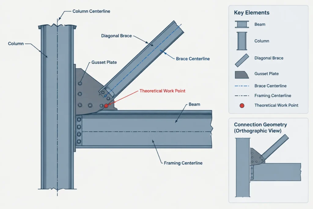
- the controlling work point;
- the brace work line and member orientation;
- the beam and column reference lines;
- the plane in which the gusset is located; and
- any offsets between member centerlines and actual connection planes.
Keeping these construction lines on a dedicated layer helps prevent the final plate outline from becoming the de facto reference. If the brace angle or framing elevation changes, the connection can then be rebuilt from its original datums rather than adjusted by eye.
Separate the Connection Zones
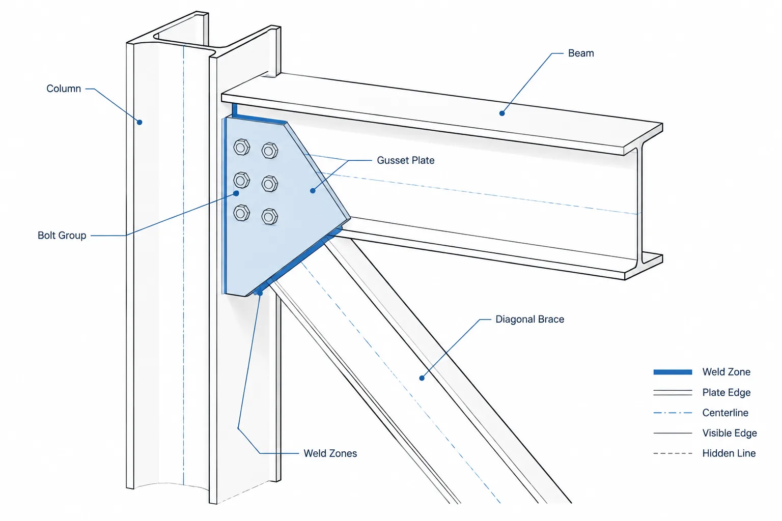
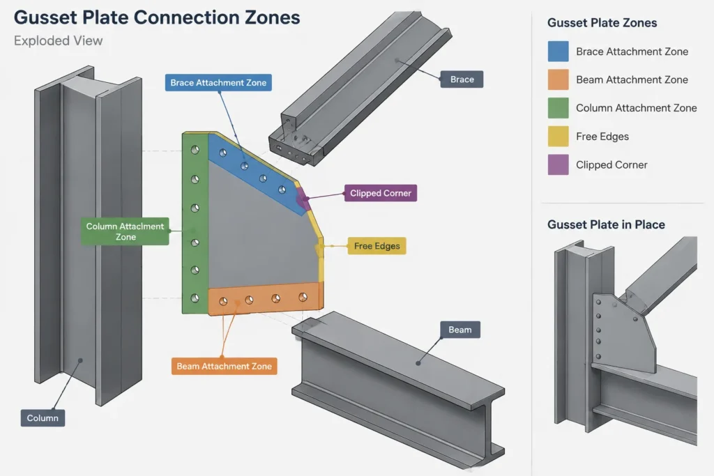
A useful way to understand a gusset is to divide it into connection zones. A typical brace gusset may have a brace connection zone, a beam attachment zone, and a column attachment zone. Other configurations may connect only to a beam, only to a column, or to additional plates and framing members.
Brace connection zone
This zone contains the bolts, welds, or intermediate connection elements that transfer force between the brace and the gusset. Its geometry may be affected by the brace shape. An HSS brace, double-angle brace, single-angle brace, channel, or wide-flange brace does not approach the plate in the same way.
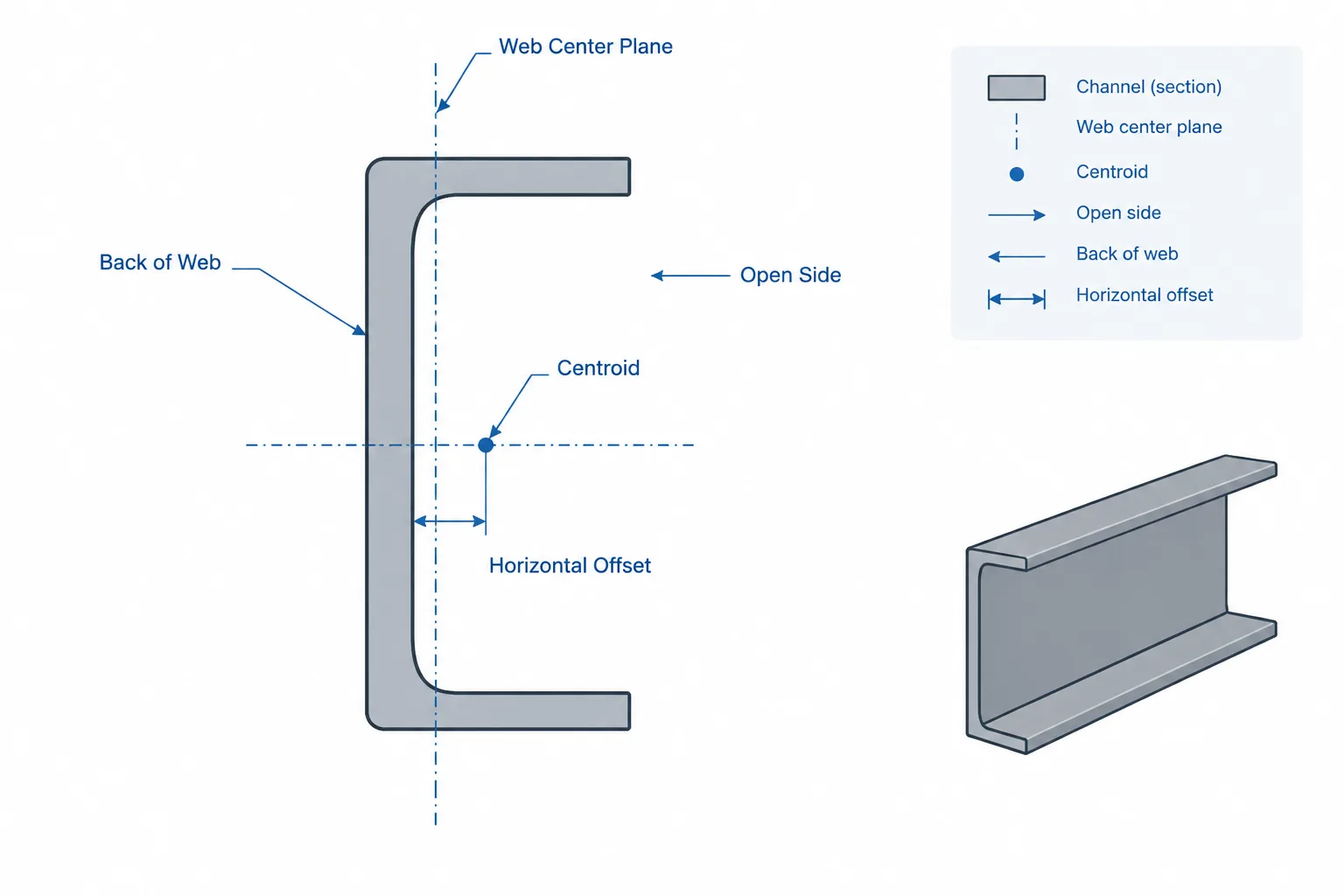
The detailer should distinguish the brace work line from the actual contacting face or connection plane. For unsymmetric shapes, these may not coincide. Connection eccentricity should not be removed merely to make the drawing appear centered; it must agree with the engineered connection arrangement.
Beam and column attachment zones
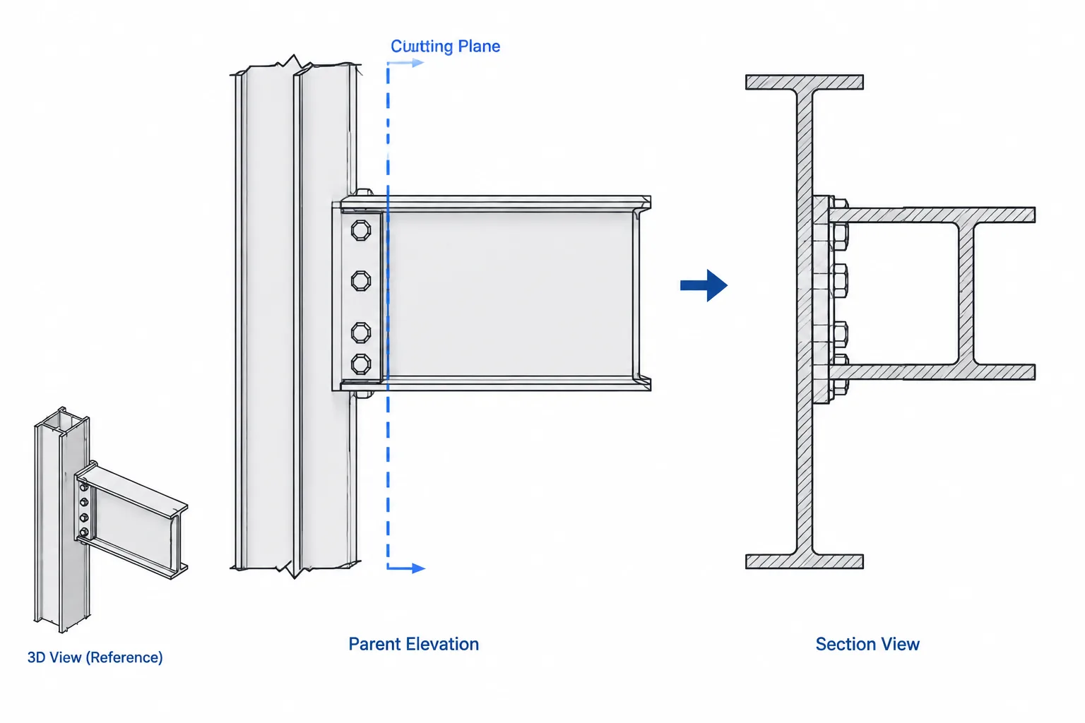
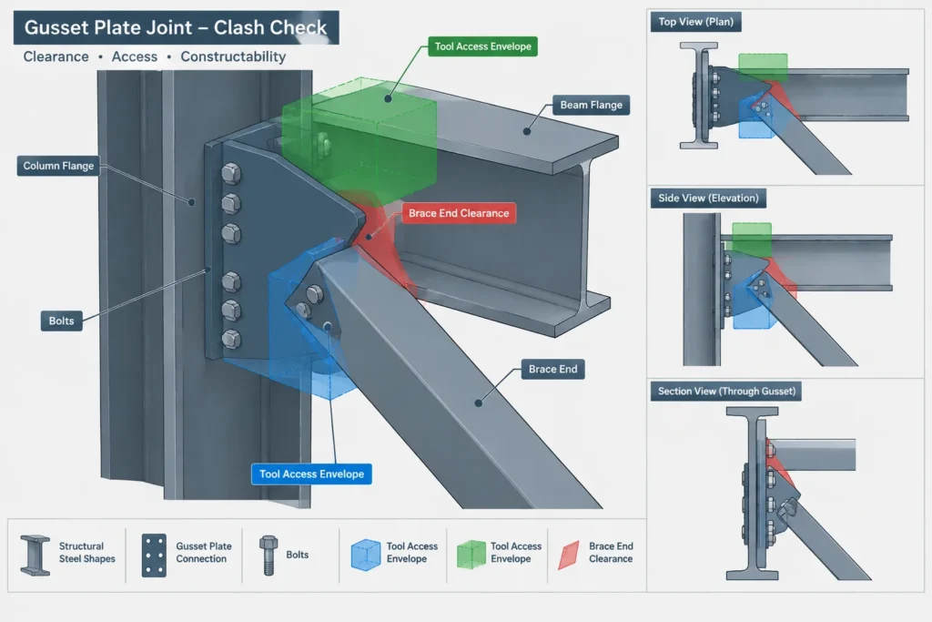
These zones transfer force from the gusset into the supporting framing. Their usable lengths may be limited by beam flanges, column geometry, existing connection plates, stiffeners, access holes, or other attachments. A gusset shown in a single elevation can conceal interference occurring perpendicular to the drawing plane, so sections or a three-dimensional review are often necessary.
Weld terminations also deserve explicit coordination. A drawn plate edge does not by itself communicate where a weld begins, ends, returns, or must stop because of an obstruction. Weld information should follow the approved connection design and project detailing practice.
Develop the Plate Outline After Locating the Connections
The plate perimeter should generally be developed after the required connection regions are established. Starting with a visually convenient triangle and forcing the bolt and weld layouts inside it can create avoidable clearance problems.
A practical sequence is:
- Establish the joint work point and all member centerlines.
- Place the supporting members using verified section geometry and orientation.
- Locate the brace and its connection plane.
- Lay out the engineered bolt groups, weld zones, or connecting elements.
- Add required clearances around member edges, fillets, fasteners, welds, and tools.
- Construct the plate perimeter around those controlling regions.
- Review the resulting free edges and corners for fabrication and structural implications.
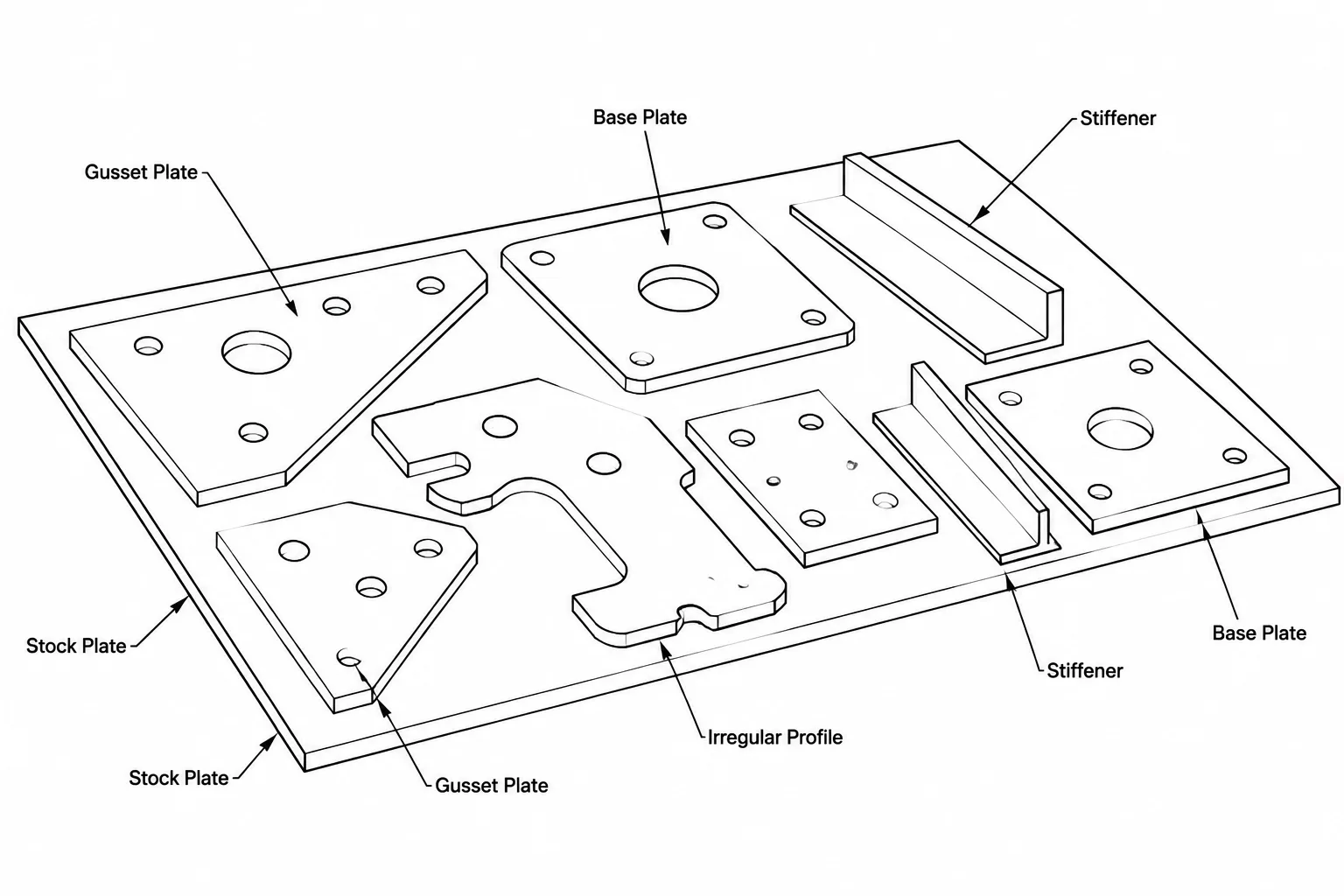
Plate corners may be square, clipped, radiused, or otherwise shaped, depending on the design and fabrication requirements. A cosmetic corner modification should never be assumed to be structurally neutral. Trimming a corner can affect available edge distance, net area, force paths, or the space needed for welding and handling.
Brace End Setback and Fit-Up
The brace end must be coordinated with both the gusset and the surrounding frame. Its setback may be referenced from a work point, a supporting-member face, a plate edge, or another defined datum. The drawing should make that reference unmistakable.
Brace setback is not the same as the visible gap in every drawing view. For a diagonal member, projected distances can differ from dimensions measured along the brace axis. A reliable CAD workflow constructs the end plane in the correct orientation and verifies the resulting true clearance.
The brace must also avoid unintended contact with beam flanges, column corners, welds, bolts, and adjacent plates. At complex joints, checking only the brace centerline can miss collisions involving the full section envelope.
Bolted Gusset Plate Details
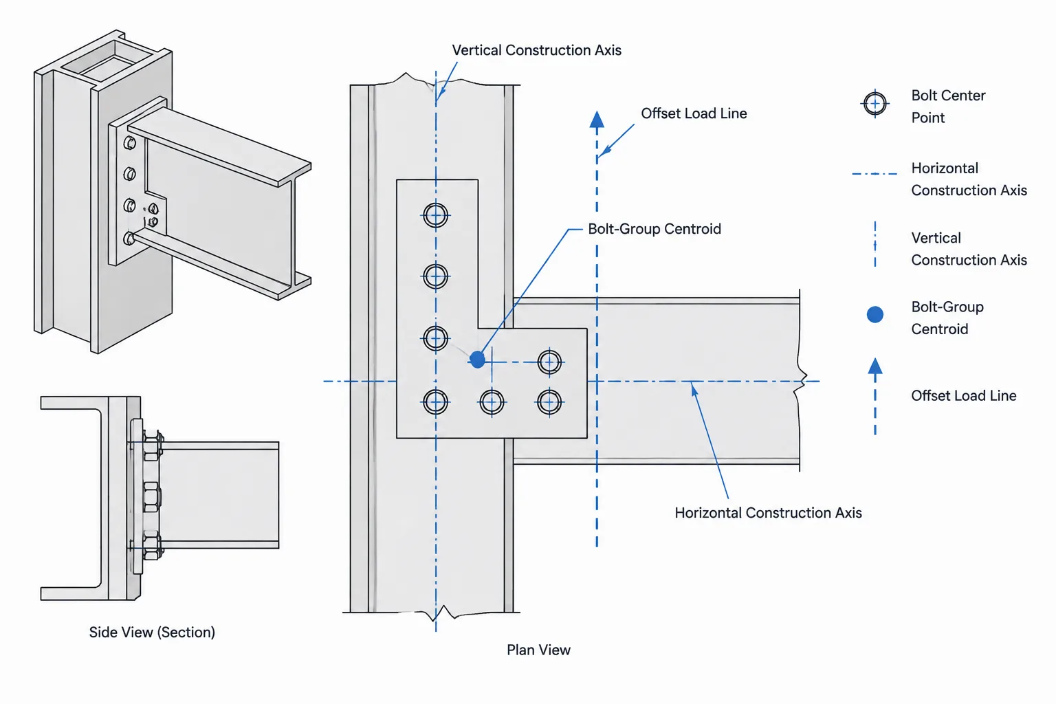
For a bolted brace connection, hole locations should be controlled from clear datums. Dimensions may be organized from the brace end, brace work line, plate edge, bolt-group centerline, or another project-defined reference. The selected method should support fabrication without requiring the shop to reconstruct design geometry.
Check the complete hole pattern rather than only the first and last holes. Useful reviews include:
- hole-center locations relative to the brace axis;
- pitch, gage, and stagger where applicable;
- clearance from plate edges and clipped corners;
- clearance from brace toes, heels, webs, flanges, or HSS walls;
- bolt-head and nut access on both sides of the connection;
- interference with welds and supporting members; and
- consistency between part drawings, assembly drawings, and CNC data.
Required hole types and minimum detailing distances depend on the connection design and governing project criteria. They should be taken from verified contract and connection information rather than inferred from a generic CAD detail.
Welded Gusset Plate Details
Welded gussets require coordination of weld length, plate contact, edge preparation when specified, access, and sequencing. A weld symbol communicates design intent, but the modeled geometry must still provide a practical location for the weld.
Potential conflicts include a gusset pushed too close to a rolled-shape fillet, a weld terminating where another plate blocks access, or intersecting welds concentrated at a congested corner. The drawing should clearly distinguish shop welds from field welds and show which component is attached to which face.
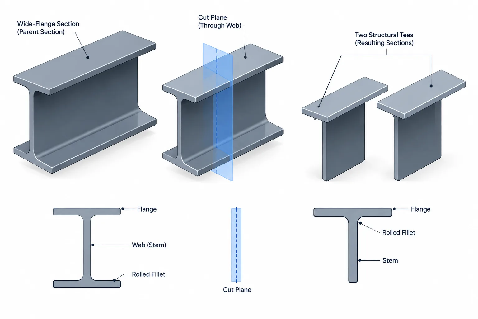
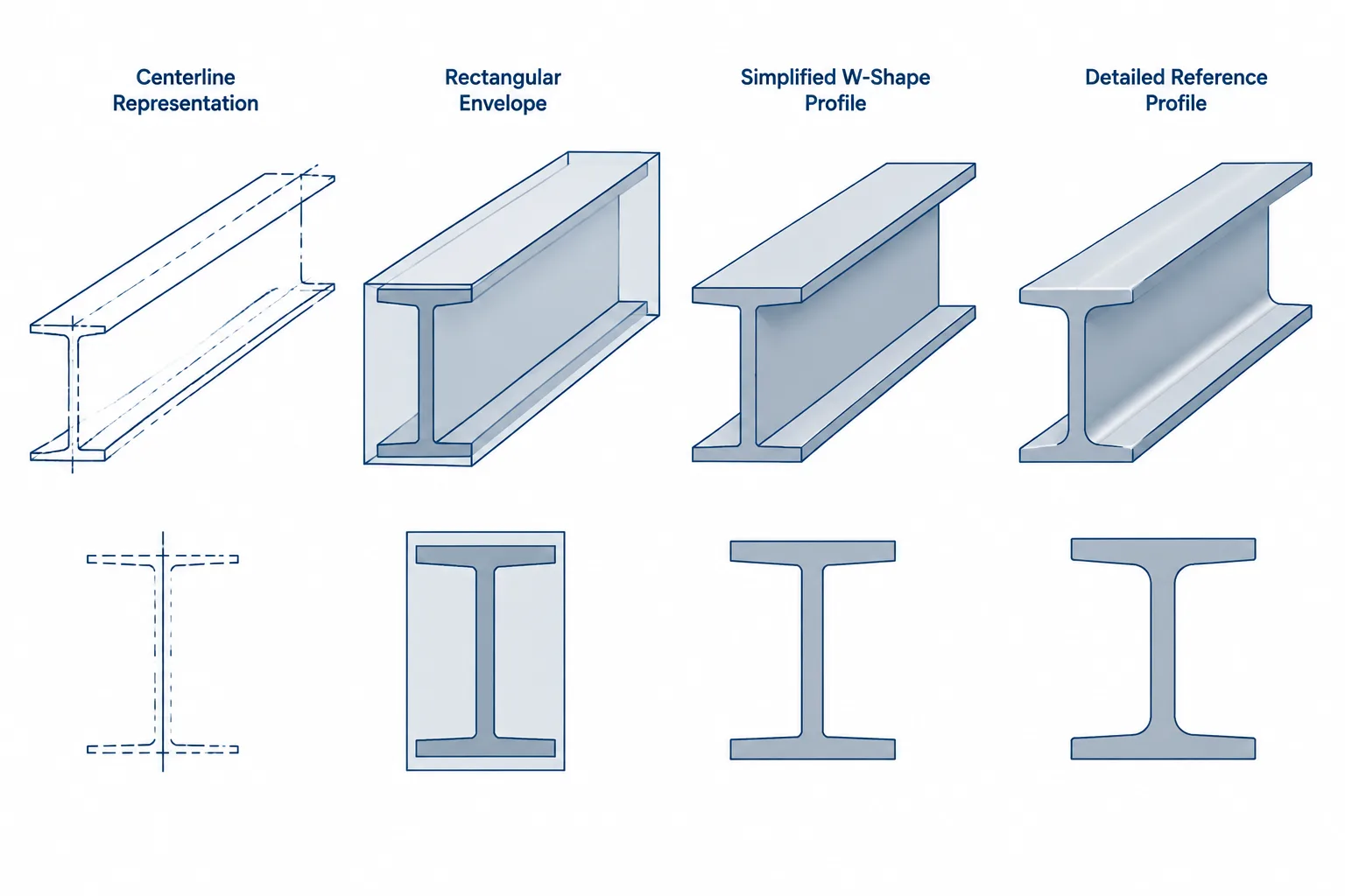
Where a gusset passes near a curved rolled-shape region, simplified sharp-corner CAD geometry can be misleading. Verified shape dimensions and required detailing clearances should be used when assessing fit.
Free Edges, Plate Stability, and Assumed Behavior
The unsupported edges of a gusset are not merely leftover geometry. Their location affects plate proportions, clearance, and potentially the behavior considered by the connection designer. Some bracing systems also require room for expected deformation or rotation at the joint.
Detailers should not independently trim, extend, or stiffen a gusset solely to improve appearance. If the proposed outline differs from the connection design, the change should be referred for engineering review. The same principle applies to adding edge stiffeners, changing attachment lengths, relocating bolt groups, or altering the relationship between the brace and work point.
Recommended CAD Review Workflow
| Review stage | Primary check | Common problem found |
|---|---|---|
| Reference setup | Work points, axes, elevations, and connection planes | Brace laid out from the wrong centerline or face |
| Member placement | Actual section orientation and envelope | Flange, toe, or HSS wall interference |
| Connection layout | Bolt groups, weld zones, and setbacks | Connection shifted to fit an arbitrary plate outline |
| Plate development | Edges, clips, corners, and attachment lengths | Insufficient room near a free edge or support |
| Access review | Bolting, welding, inspection, and erection access | Geometry fits digitally but cannot be assembled |
| Document comparison | Plans, elevations, sections, models, and part details | Mirrored, rotated, or mismatched hole patterns |
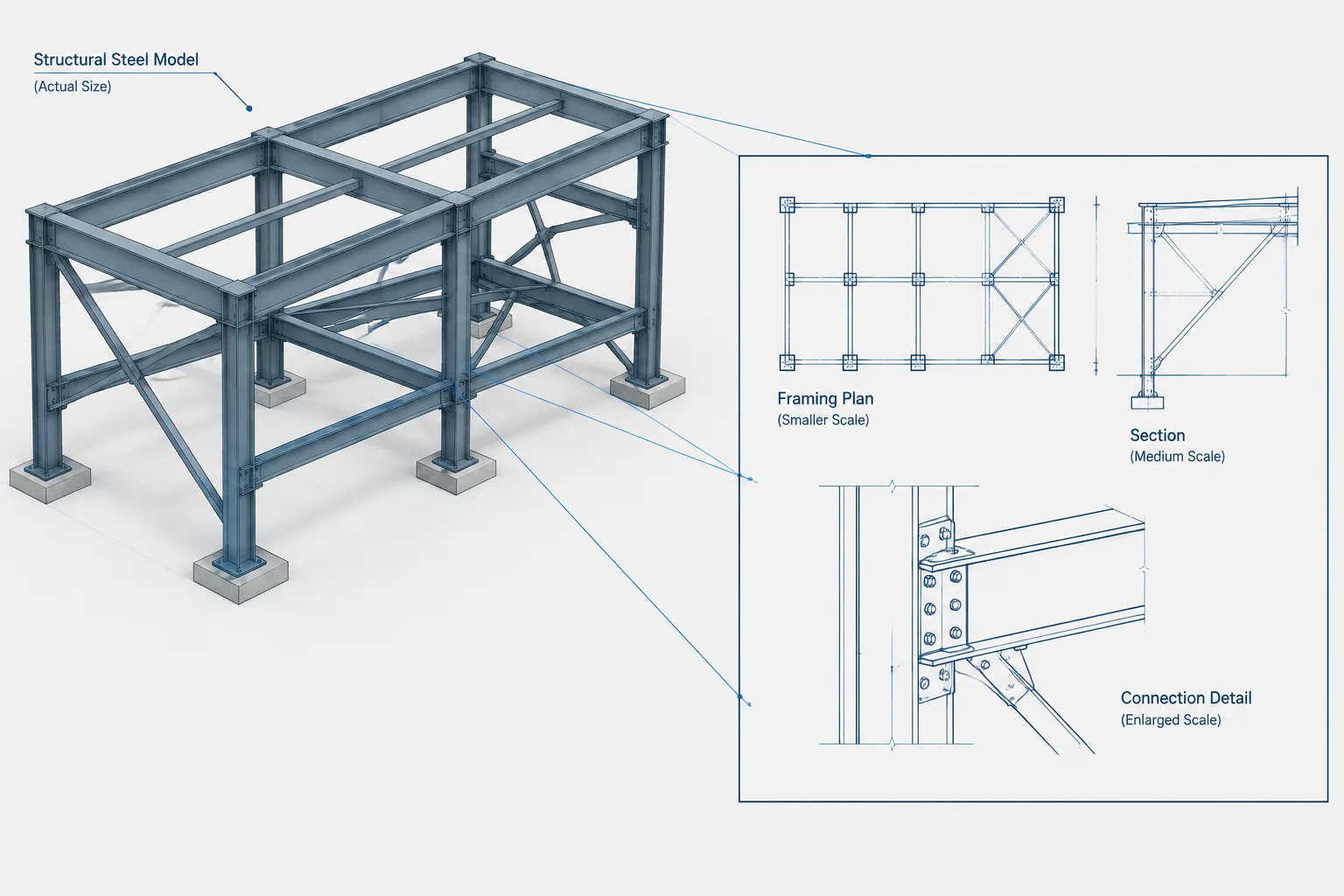
A three-dimensional model is valuable for clash detection, but it does not replace dimension and datum checks. Model components can appear aligned while being controlled from unrelated reference points. Final shop information should communicate the geometry without depending on visual measurement from the model.
Final Gusset Plate Detailing Checklist
- Confirm the controlling work point and member axes.
- Verify the gusset plane and any offsets from framing centerlines.
- Use the correct brace shape, orientation, and connection face.
- Coordinate brace setback with the actual end plane.
- Check complete bolt groups and weld zones against plate edges.
- Review rolled fillets, HSS corners, and other non-square shape geometry.
- Provide access for installation, welding, tightening, and inspection.
- Check the joint in section or three dimensions, not only in elevation.
- Keep plate outline changes consistent with the engineered force path.
- Ensure part, assembly, erection, and model information agree.
Good gusset plate detailing makes the connection intent traceable. When work points, member axes, connection zones, and fabrication clearances are established before the plate perimeter, the resulting detail is easier to verify and less likely to require field correction.