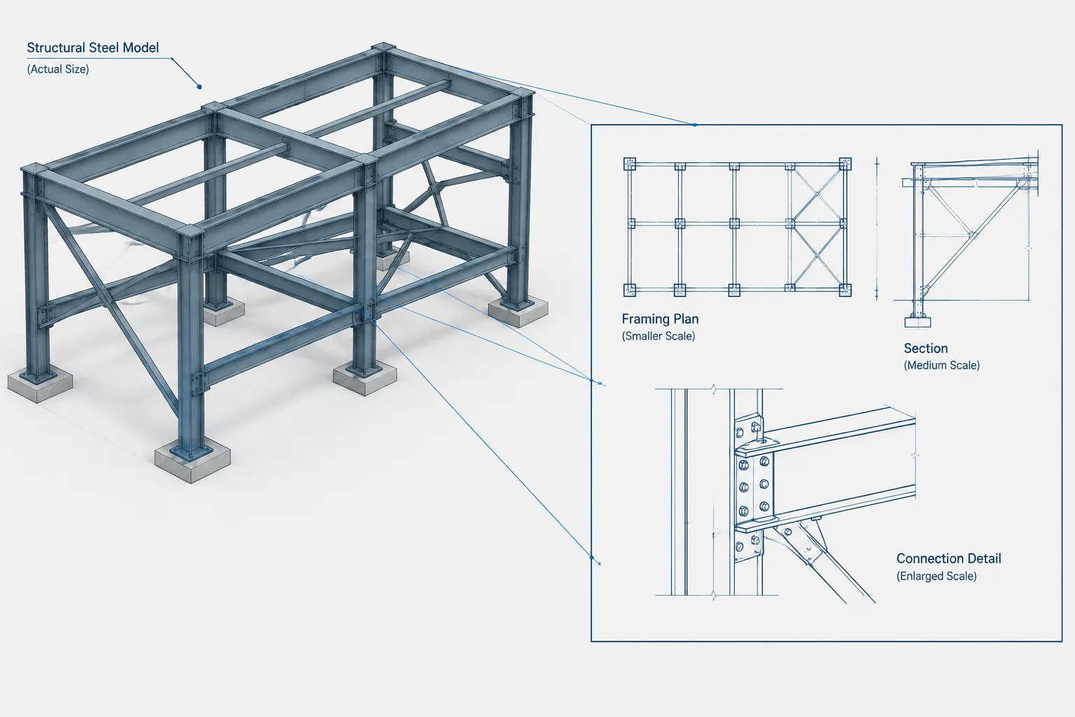
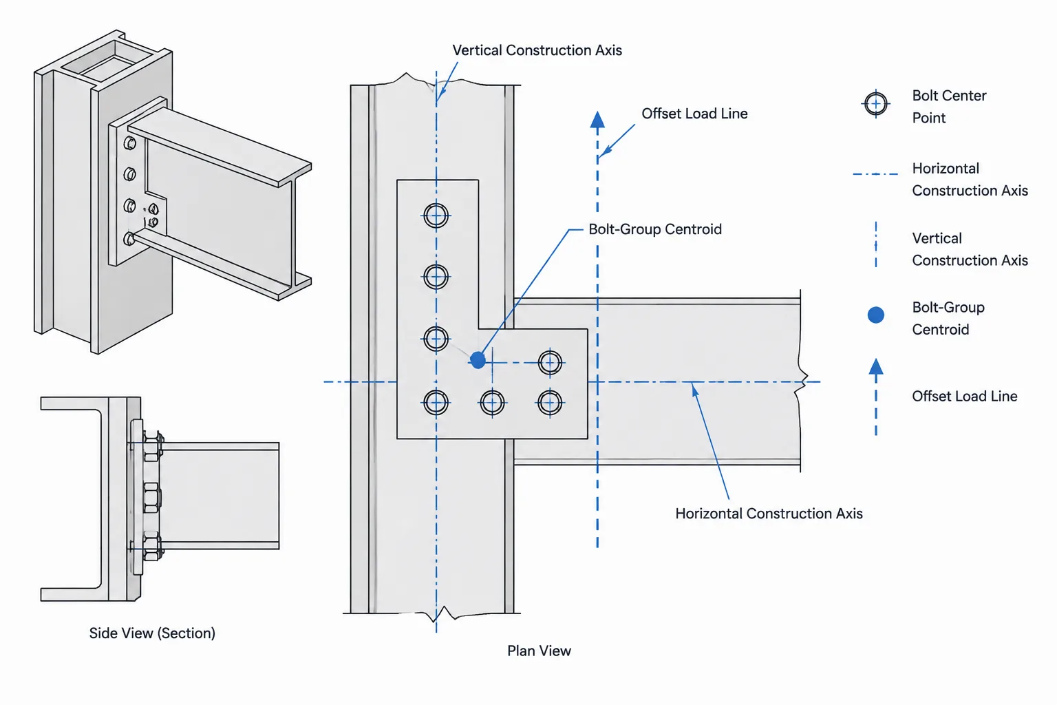
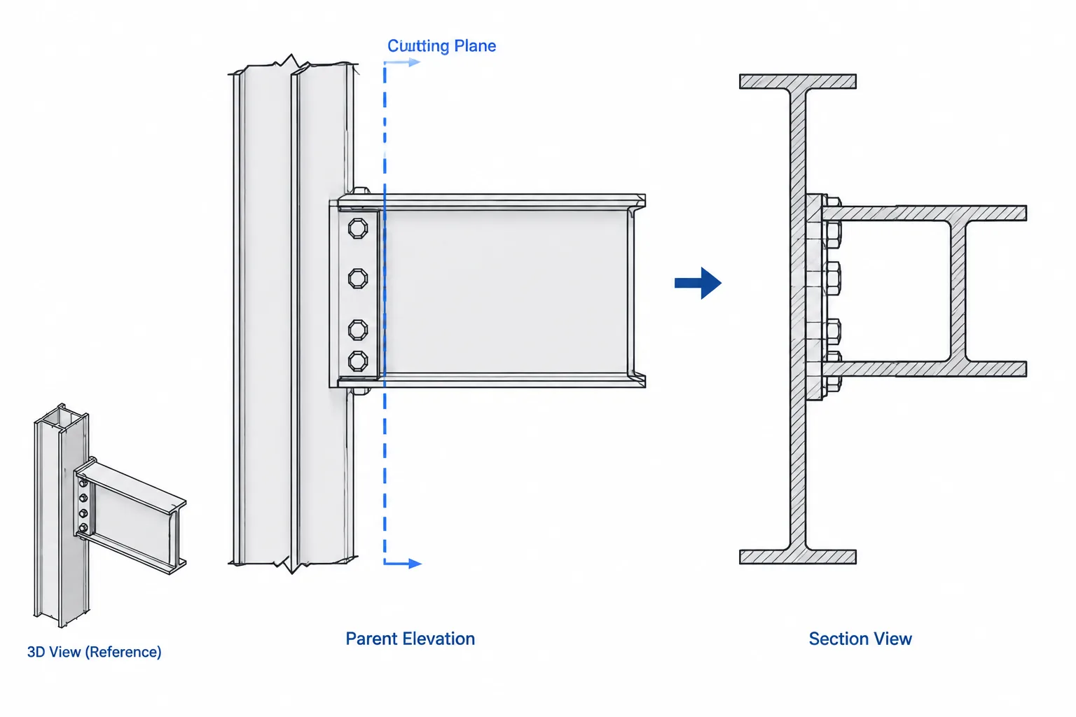
Structural bolt projection beyond the nut is a small geometric detail with practical consequences. Too little visible thread may raise questions about nut engagement, while excessive projection can interfere with plates, stiffeners, finishes, tools, or adjacent members. The detail is especially easy to overlook when a connection is modeled as flat plates with symbolic bolts rather than as a complete stack of steel, washers, nuts, and bolt ends.
Bolt projection is not a stand-alone dimension selected by appearance. It results from the specified bolt length, the total connected grip, the washer arrangement, the nut, and the characteristics of the selected fastener assembly. Designers and detailers should therefore coordinate the complete assembly rather than assigning an arbitrary stick-out value. Acceptance requirements must come from the governing project documents, applicable standards, and the approved fastener installation procedure.
What Is Bolt Stick-Out?
Bolt stick-out, also called bolt projection, is the portion of the bolt that extends beyond the outer face of the installed nut. In a simplified side view, it is the visible threaded end on the far side of the connection.
This projection should not be confused with several related dimensions:
- Bolt length is the designated length of the bolt measured according to the convention for that bolt type.
- Grip is the total thickness of the connected plies contained between the bolt head and nut, with the treatment of washers considered separately in the assembly selection process.
- Threaded length is the portion of the shank carrying threads.
- Nut engagement describes how the nut engages the available threads.
- Head-side clearance and nut-side clearance are the spaces needed around each end for installation, tightening, and inspection.
These terms describe different parts of the same assembly. A bolt can have adequate overall length yet still create an undesirable thread location or excessive projection if the connection stack changes.
Why Projection Changes
Connected-ply thickness
The starting point is the actual stack of connected material. A beam web connection might include the web and one or more connection plates. A splice can include main material, splice plates, fillers, and shims. Coatings or compressible materials generally should not be treated casually as structural plies; their effect must be addressed by the project requirements and connection design.
If any steel thickness changes during detailing, the bolt assembly needs to be reviewed. Replacing a plate, adding a filler, or changing a member size can alter the grip even when the hole pattern remains unchanged.
Washers and installation components
The washer arrangement affects the total assembled thickness and available projection. Washers may occur under the head, under the nut, or in another specified arrangement. Some fastener systems also use installation or verification components that occupy space in the assembly.
A CAD model that shows only a bolt head and nut can therefore underestimate the real stack. Detailers should model or schedule the intended washer arrangement when clearance is tight, even if washers are omitted from less detailed general views.
Bolt length increments
Structural bolts are selected from available manufactured lengths rather than cut to a unique length for every connection. The selected bolt may consequently produce more projection than a purely geometric minimum would suggest. The goal is not to make every bolt end visually flush; it is to select a compliant assembly that fits the connection and can be installed as intended.
Thread location
Projection beyond the nut does not reveal where the threads lie inside the connected material. The thread runout and threaded portion must also be considered. When thread position is important to connection behavior or is controlled by the design, checking only the exposed end is insufficient.
Projection Is Also a Clearance Issue
In open framing, extra bolt projection may appear harmless. In compact connections, however, the protruding end can clash with surrounding steel or obstruct field work. Common conflict zones include:
- Column flange-to-web corners and rolled-shape fillet regions
- Opposing bolts installed from the other side of a narrow member
- Stiffener, doubler, continuity, and diaphragm plates
- HSS faces where internal access or concealed components are limited
- Beam end plates positioned close to another connection
- Deck, wall systems, cladding supports, and architectural finishes
- Protective enclosures, fireproofing boundaries, and equipment clearances
- Edges where tools must pass around the nut during tightening
A clash check based only on the nut envelope misses the bolt end. Conversely, a model that uses an excessively long generic bolt may report false clashes. The modeled projection should be realistic enough for the coordination purpose, while final selection remains tied to the approved fastener assembly.
Head Side and Nut Side Must Be Identified
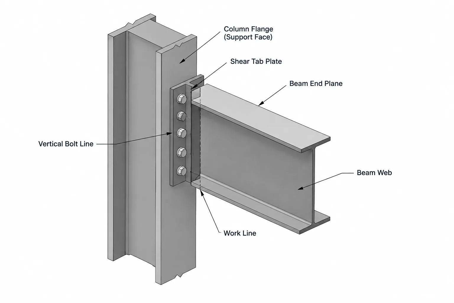
Bolt orientation is often treated as interchangeable in schematic drawings, but it can matter during fabrication and erection. Reversing a bolt moves the projecting end, nut, and associated tightening activity to the opposite side of the connection. That may solve one clash while creating another.
When orientation is important, the drawing should communicate it consistently in the relevant view or note. Useful considerations include:
- Which side is accessible for insertion?
- Which side provides room for tightening equipment?
- Will the bolt head pass behind an adjacent plate or flange?
- Does the nut side remain visible for inspection?
- Will projection interfere with another trade or finish?
- Can the bolt be replaced later if access is blocked?
Do not rely on a generic bolt symbol to control orientation when the physical direction is essential to fit-up.
A Practical Connection Stack-Up Check
A simple stack-up review can catch most projection problems before shop drawings are released.
| Check item | Question to answer | Common oversight |
|---|---|---|
| Connected plies | What steel and filler thicknesses are captured by the bolt? | A shim or reinforcing plate is omitted. |
| Washer arrangement | Which components occur under the head and nut? | CAD hardware shows no washers. |
| Bolt selection | Is the selected length available and appropriate for the complete stack? | A theoretical length is scheduled without assembly review. |
| Thread location | Where do the threads and runout fall relative to the plies? | Only exposed stick-out is checked. |
| Nut-side envelope | Is there room for the nut, projection, tool, and inspection? | Clearance is measured only to the nut face. |
| Head-side envelope | Can the bolt be inserted and held during tightening? | An adjacent plate blocks insertion. |
| Orientation | Does reversing the bolt change access or interference? | Plan and section views imply different directions. |
CAD Modeling Approaches
The appropriate bolt representation depends on the drawing and coordination objective.
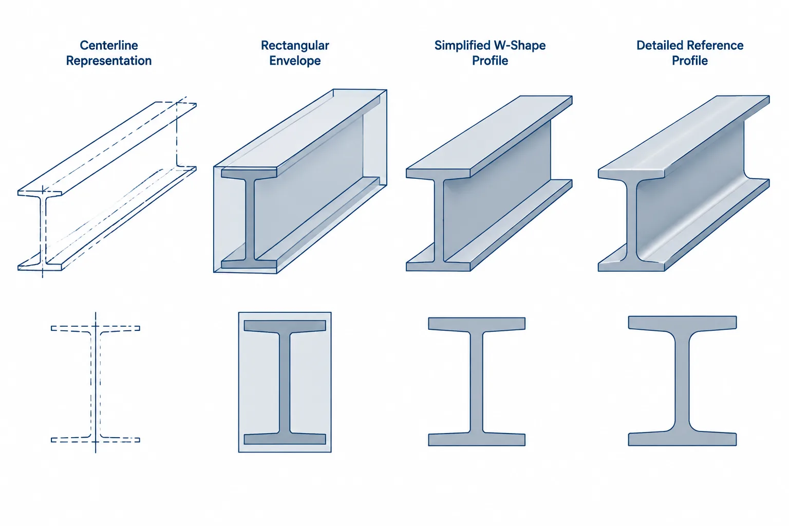
Symbolic representation
For plans, elevations, and connection diagrams at small scale, a centerline or simplified bolt symbol may be sufficient. The bolt schedule or connection note then carries the assembly information. This keeps drawings readable but is not reliable for close-clearance studies.
Simplified solid representation
A simplified solid with a head, shank, nut, washers, and projected end is useful for most three-dimensional clash reviews. Threads generally do not need to be modeled as helical geometry. The important features are the assembly length and realistic external envelopes.
Detailed connection representation
Higher-detail hardware may be justified around congested nodes, specialty equipment, or architectural interfaces. Even then, the model should not imply that a generic fastener object has verified the final bolt length. Model metadata, schedules, and shop information must remain coordinated.
Common Detailing Mistakes
- Using one bolt length throughout a connection: Different plate stacks within the same joint may require separate assembly selections.
- Ignoring fillers and shims: Small stack changes can affect projection and thread position.
- Checking only the bolt centerline: A clear hole axis does not prove that the nut, head, or tool envelope fits.
- Assuming more projection is always safer: Additional length can create clashes and does not replace a proper engagement and thread-location check.
- Showing inconsistent orientation: A plan may place nuts on one side while a section suggests the opposite arrangement.
- Treating the model as the specification: Generic CAD hardware should not override project requirements or approved installation information.
Coordination Before Release
Before issuing connection details, compare the bolt schedule, plate stack, washer arrangement, orientation, and surrounding geometry. Review sections through the most congested bolt rows rather than relying only on an elevation. Where access is questionable, show the connection from both sides or create a local section that includes the full hardware envelope.
Structural bolt projection beyond the nut is ultimately the visible result of several coordinated decisions. Treating it as part of the complete connection stack—rather than as an isolated cosmetic dimension—helps prevent hardware clashes, inaccessible nuts, inconsistent drawings, and avoidable field questions.