Hollow structural sections require more end-condition coordination than their simple exterior geometry suggests. An HSS member may terminate with an open end, a welded cap, a flush closure, a bolted end plate, a base plate, or a concealed connection component. Each option affects fabrication, welding, coating, drainage, inspection, appearance, and the dimensions shown on shop drawings.
The first detailing question should not be “What plate closes the tube?” It should be “What must this end condition do?” A plate intended only to close an opening is different from a plate that transfers a connection force. Likewise, a sealed-looking detail is not necessarily watertight, and a vent hole provided for fabrication may not function as a service-life drain.
Common HSS End Conditions
| End condition | Primary purpose | Key coordination issue |
|---|---|---|
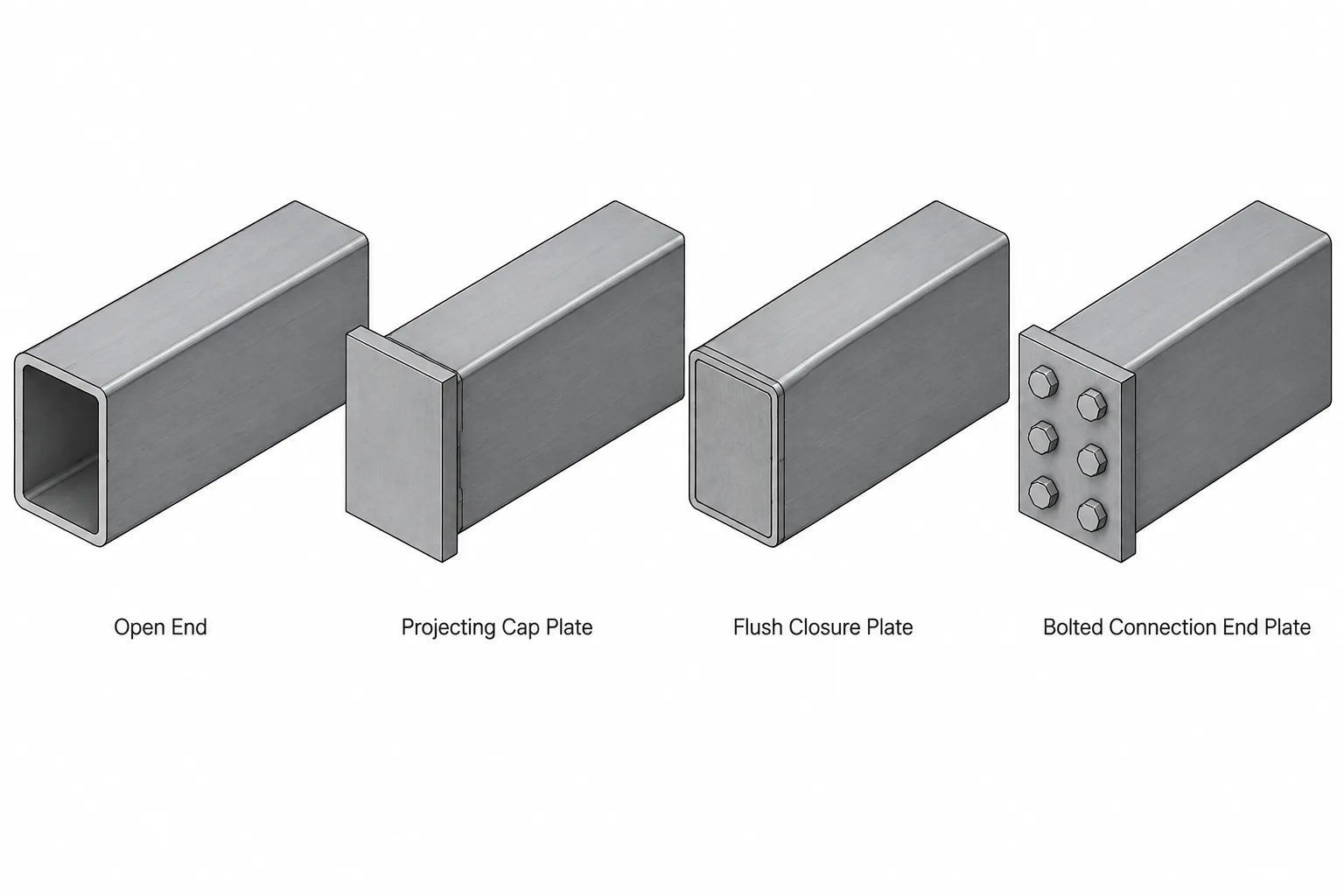
| Open end | Leaves the HSS interior accessible or unobstructed | Exposure, drainage, debris, coating, and appearance |
| Cap plate | Covers the open end with a plate over the HSS perimeter | Plate projection, weld profile, drainage, and architectural finish |
| Flush closure plate | Closes the end while keeping the termination visually compact | Fit-up, weld access, plate position, and finished surface |
| Connection end plate | Transfers force through bolts, welds, or attached framing | Structural load path, bolt access, plate deformation, and weld design |
| Base or bearing plate | Transfers load to supporting steel, concrete, masonry, or another component | Bearing, anchors, grout, leveling, drainage, and erection access |
| Special insert or knife plate | Creates a concealed or partially concealed connection | Interior access, slots, welding sequence, and corrosion protection |
Open Ends Are Still a Designed Condition
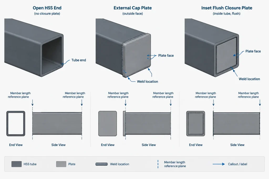
An open HSS end may be intentional. It can provide access for welding, bolting, cleaning, coating, or later installation of another component. It may also allow water to leave a member rather than trapping it behind a closure.
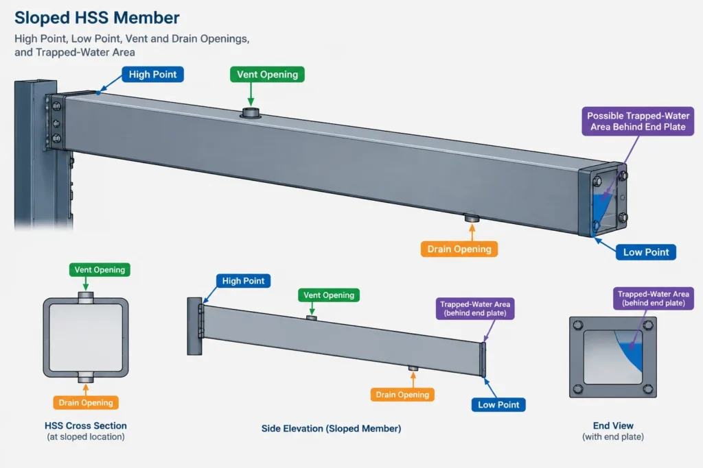
Open ends require deliberate treatment when they are exposed to weather or visible in the finished structure. The drawings may need to address edge preparation, burr removal, coating continuity, screening, orientation, or protection from debris. For sloped and exterior members, the lowest point of the actual cavity matters more than the apparent end location in a simplified elevation.
A model should not receive a cap merely because an open tube looks unfinished on screen. Adding an undocumented closure can change member length, interfere with another part, block drainage, and create unreviewed welding.
Cap Plates and Flush Closure Plates
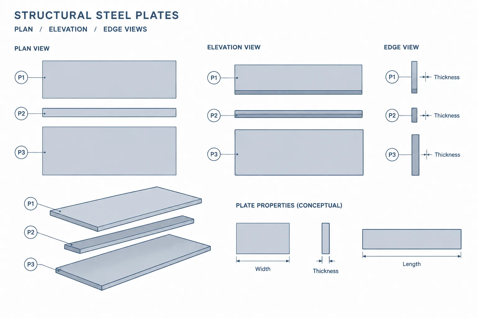
A cap plate typically sits over the HSS end and covers its perimeter. Its outline may match the HSS exterior, project beyond it, or follow another geometry defined by the design. The plate can be architectural, protective, structural, or a combination of these functions.
A flush closure plate is commonly placed within or near the end profile so that the finished termination remains close to the HSS outline. This can produce a cleaner appearance, but it also makes fit-up and weld access more sensitive. The detail must clearly establish whether the plate face is flush with the HSS end, recessed, or offset beyond it.
For either configuration, the drafter should avoid assuming that a generic rectangular outline accurately represents the finished plate. Rectangular and square HSS have rounded exterior corners, while round HSS requires a circular interface. Whether the plate follows those corners, uses a simpler cut profile, or projects beyond them should be shown rather than inferred.
A closure is not automatically watertight
A continuous-looking weld symbol or rendered model does not by itself establish a verified watertight assembly. Weld termination, porosity, distortion, coating damage, and connections added later can all affect water entry. If water exclusion is a project requirement, it should be explicitly coordinated with the responsible designer, fabricator, coating provider, and inspection requirements.
Connection End Plates Are Not Just Caps
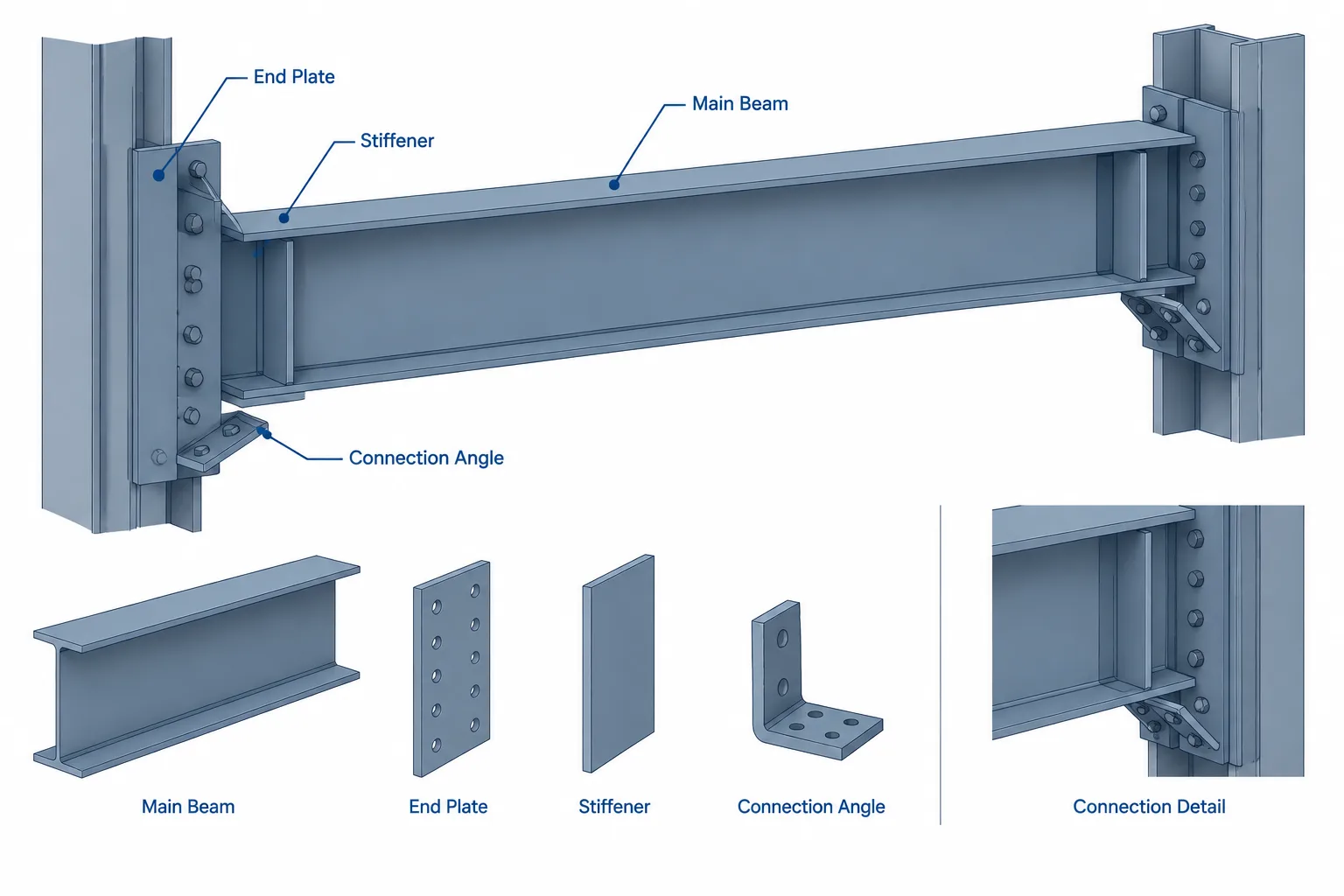
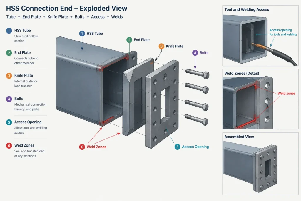
An HSS connection end plate may close the section, but its primary role is usually force transfer. It can participate in axial, shear, bending, or combined-force behavior. Plate thickness, bolt layout, weld configuration, and the HSS wall response must therefore come from the connection design rather than from a typical closure detail.
The distinction is important in both the model and bill of materials. Calling every terminal plate a “cap plate” can hide its structural function. A useful part description identifies the plate consistently, while the connection detail shows how it attaches and what other members or fasteners it engages.
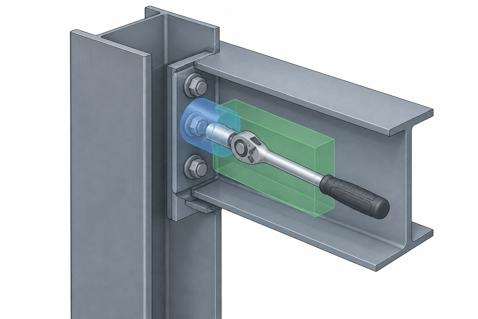
Interior access is another major concern. Unlike a W-shape, an HSS does not normally provide open access to both sides of its wall. Nuts, backing, internal welds, and concealed plates may require access openings, installation sequencing, or proprietary connection components selected by the project team. A visually plausible CAD assembly may still be impossible to fabricate or tighten.
Vent, Drain, Weep, and Access Openings
Small openings in HSS details can serve very different purposes. Their function should be identified instead of leaving the shop to interpret an unlabeled circle or slot.
- Vent openings allow air, gases, or process fluids to move during fabrication or coating operations.
- Drain openings allow liquid to leave the member during processing or service.
- Weep openings provide an exit path for incidental moisture that reaches an enclosed area.
- Access openings allow tools, fasteners, welding, inspection, or internal component installation.
One opening should not automatically be assumed to perform every function. Its location relative to the member orientation is critical. A hole near the bottom in one shop position may become the high point after the member is erected or rotated. Sloped HSS can also create isolated low points at plates, weld dams, or internal attachments.
Hot-dip galvanizing requires particular coordination because enclosed volumes need suitable paths for air and process materials. The galvanizer and fabricator should review hole locations and the member’s processing orientation. The detailer should not add, relocate, or omit these openings solely for graphical convenience.
Member Length and Plate Reference Planes
End closures often create ambiguity in HSS length dimensions. A stated overall length might refer to the cut end of the tube, the outside face of a cap plate, the face of a connection plate, or a work point beyond the physical member.
Shop details should distinguish among these references when more than one is present:
- HSS cut length from end to end;
- outside-to-outside length of attached plates;
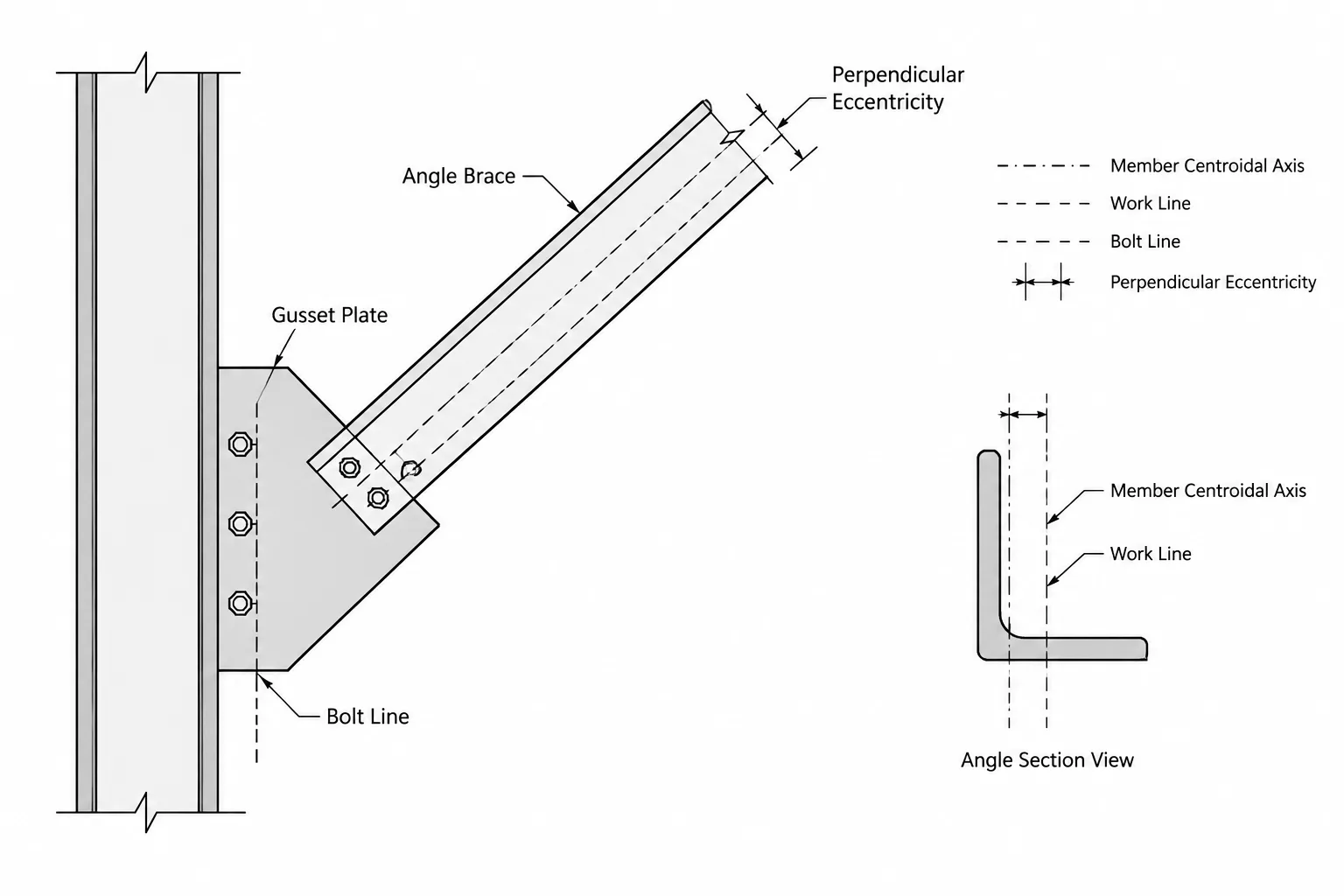
- plate face to work point or support line;
- connection setback from a grid, column line, or member centerline;
- projection of a plate beyond the HSS end.
A section or enlarged end view is often more reliable than stacking additional dimensions onto a general elevation. The reference face should also be consistent between the CAD model, shop drawing, and material list.
Weld and Fit-Up Considerations
HSS end details should be reviewed as fabricable assemblies rather than flat plate outlines. The HSS wall, rounded corners, plate edge, weld size, weld access, and anticipated welding sequence all interact. A plate fitted inside the section can be especially sensitive to actual interior geometry and wall variation.
Published shape dimensions are valuable for reference, but they do not replace fit-up allowances or fabrication judgment. Nominal wall information and simplified CAD geometry should not be treated as a guarantee that an insert will slide into every manufactured section. Fit-critical internal parts require coordinated dimensions, tolerances, and an appropriate fabrication plan.
Practical CAD and Drawing Checklist
- Identify whether the end plate is a closure, connection component, bearing component, or combination.
- Model the HSS orientation correctly, including slope and the actual high and low points.
- Show whether the tube end is open, capped, flush-closed, slotted, or fitted with an insert.
- Define the plate reference plane and distinguish tube cut length from overall assembly length.
- Use a section view where internal plate position or access cannot be understood from the elevation.
- Label vent, drain, weep, and access openings by function.
- Check tool access, bolt installation, weld access, and inspection access.
- Coordinate coating and galvanizing needs before finalizing closure welds and holes.
- Do not infer watertightness from appearance alone.
- Verify all structural plate, weld, bolt, and opening requirements with the project design information.
Why End-Condition Clarity Matters
An HSS end is a small portion of the member, but it can control whether the assembly drains, coats, fits, connects, and installs as intended. Clear drawings separate the geometry of the hollow section from the purpose of each attached plate and opening. That distinction reduces shop questions and prevents a cosmetic modeling choice from becoming an unintended fabrication instruction.