A steel angle designation identifies its leg sizes and thickness, but it does not fully describe how the angle is positioned in a structure. The same unequal-leg angle can be installed with either leg vertical, rotated into another plane, placed on the near or far side of a supporting member, or mirrored to create an opposite-hand part.
That flexibility makes steel angle orientation a frequent source of drafting and fabrication errors. Abbreviations such as LLV and SLV are useful, but only when the drawing provides enough context to make “vertical” unambiguous. A complete detail should also establish which leg is connected, where the heel and toes are located, and whether the part has a required hand.
What an Angle Designation Does—and Does Not—Tell You
An angle designation communicates the nominal leg dimensions and thickness. For an unequal-leg angle, the longer leg is commonly listed before the shorter leg in U.S. shape references. The designation describes the section, not its installed rotation.
By itself, the designation does not answer these questions:
- Is the long leg vertical or horizontal?
- Which leg connects to the beam, column, wall, plate, or other support?
- Does the angle sit on the near side or far side of the supporting element?
- Do the angle toes point inward or outward?
- Is the part left-handed or right-handed?
- Where is the member line or CAD insertion point relative to the heel?
For equal-leg angles, LLV and SLV do not apply because the legs have the same nominal size. Orientation may still matter when holes, cuts, welds, or attached components make the finished part asymmetric.
LLV and SLV Meaning
Long Leg Vertical
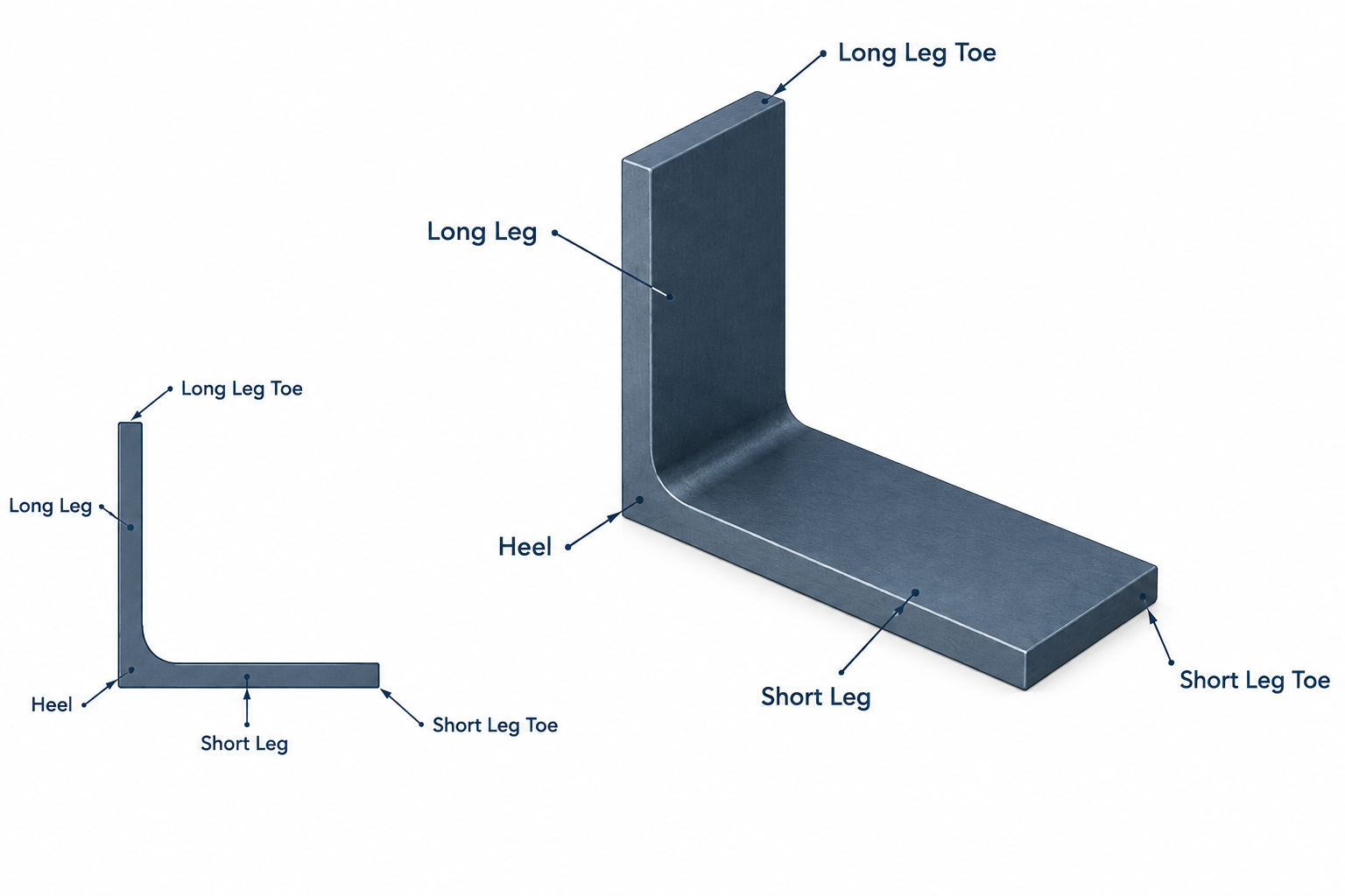
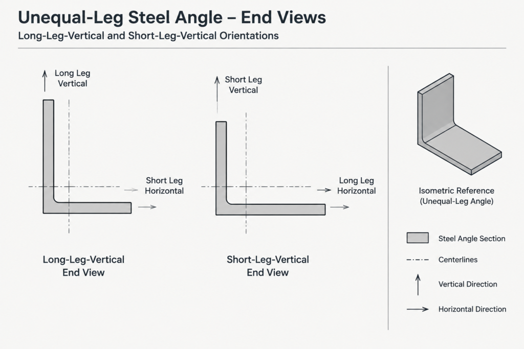
LLV means long leg vertical. In a conventional elevation or cross-section, the longer leg is shown in the vertical direction and the shorter leg extends horizontally. This description is often used for lintels, framing angles, shelf angles, and other details where one leg can clearly be identified as vertical.
Short Leg Vertical
SLV means short leg vertical. The shorter leg is oriented vertically, leaving the longer leg to extend horizontally or in the other visible direction.
These abbreviations describe rotation, not connection function. LLV does not automatically mean that the long leg is the connected leg. An angle could have its long leg vertical while its horizontal short leg bears on or connects to another component. The actual weld, bolt, or bearing detail must establish how forces and attachments are transferred.
Why “Vertical” Can Be Ambiguous
LLV and SLV work best when the angle is shown in a view with an obvious vertical direction. They can become unclear in plan views, sloped framing, skewed connections, and three-dimensional models.
For example, an angle attached along a sloped member may have a leg that is perpendicular to the member but not vertical relative to the building. Similarly, a plan detail may show an angle lying in a horizontal plane, where neither visible leg is vertical. In these cases, more direct language is usually preferable:
- Long leg against web
- Short leg against wall
- Long leg horizontal
- Outstanding leg toward grid line
- Toe facing outward
- Angle on near side of web
Project-specific abbreviations should be defined in the drawing notes or symbol legend. A familiar abbreviation should not be expected to resolve an unclear view by itself.
Connected Leg, Outstanding Leg, Heel, and Toe
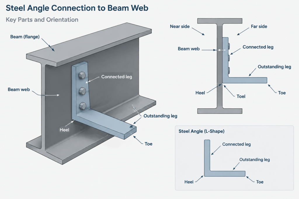
Angle orientation is easier to describe when the section terminology is used consistently.
| Term | Practical meaning | Detailing importance |
|---|---|---|
| Connected leg | The leg attached to the supporting or supported element | Controls bolt placement, weld location, gage, and fit |
| Outstanding leg | The leg projecting away from the connected surface | Affects clearance, interference, and attachment geometry |
| Heel | The outside intersection region where the two legs meet | Useful as a stable reference for locating and orienting the angle |
| Toe | The free edge of either angle leg | Important for edge distances, clearances, and directional notes |
| Inside fillet | The curved transition at the inside corner | Can interfere with plates, washers, welds, or tightly fitted parts |
Calling out the connected leg is often more useful than stating LLV or SLV alone. A note such as “long leg connected to web” directly identifies the attachment surface. The drawing can then show whether that leg is vertical, sloped, or rotated in space.
Near Side, Far Side, and Angle Hand
An angle can look correct in a section while still being placed on the wrong side of a member. Near-side and far-side information is especially important for clip angles, edge angles, and attachments to webs or HSS walls.
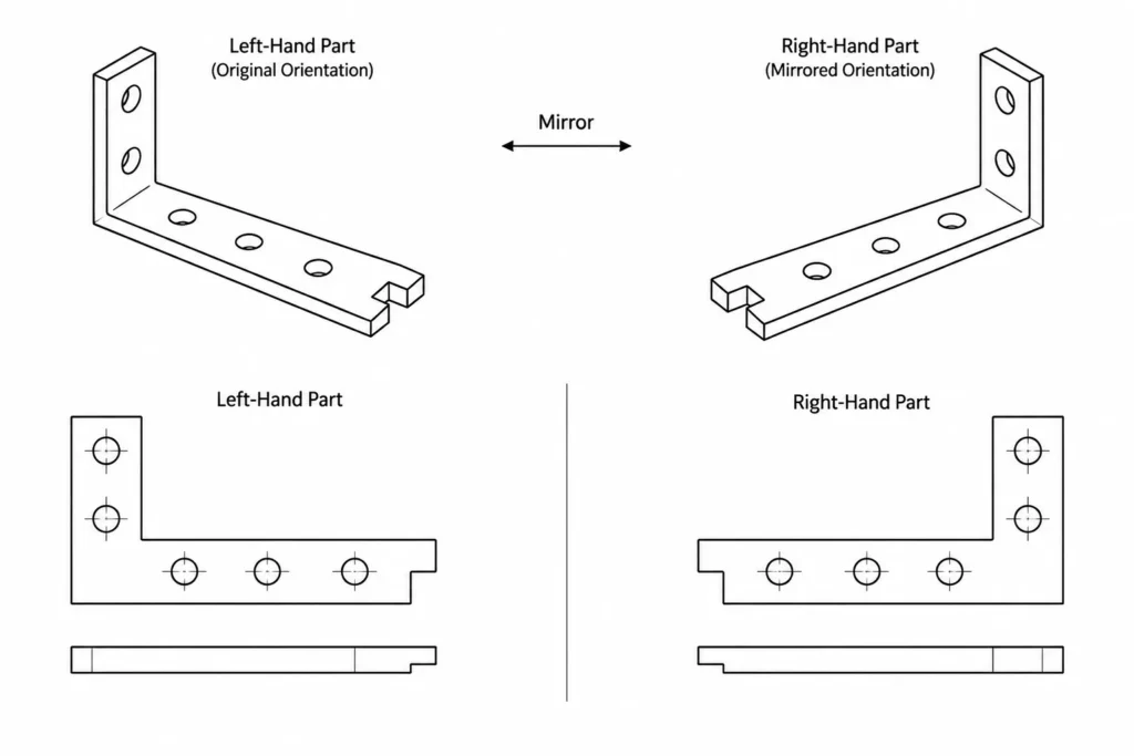
Handedness becomes significant when an angle contains a nonsymmetric hole pattern, cope, notch, bevel, welded plate, or other feature. Mirroring such a part changes the relationship between the features and the heel or toes. Two pieces cut from the same angle size may therefore be different fabricated parts.
A reliable drawing identifies handed parts explicitly or provides separate views. Depending on the project workflow, this may be done with left-hand and right-hand marks, unique piece marks, orientation sketches, or clearly dimensioned shop details. Simply mirroring a CAD block without reviewing holes and cuts can produce an incorrect opposite-hand component.
Dimensioning Angle Orientation Clearly
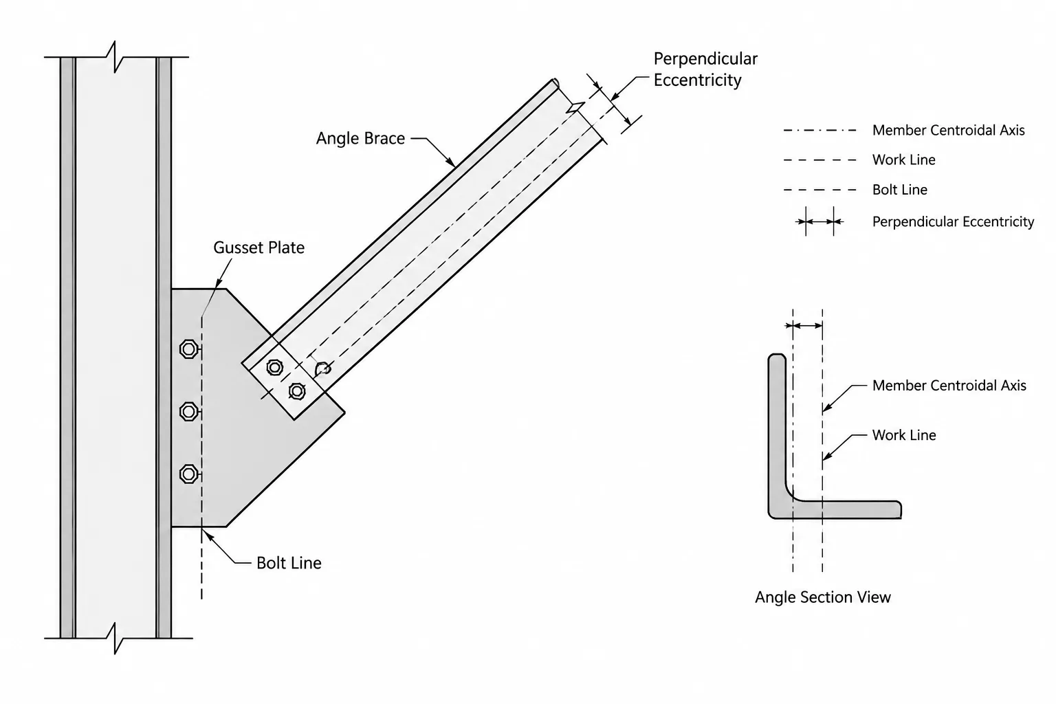
Dimensions should be taken from references that remain clear in fabrication and checking. Useful references may include the back of a leg, the heel, a member work line, the end of the angle, or the centerline of a hole group.
A practical angle detail normally establishes:
- The complete angle designation
- The connected leg and outstanding leg
- The direction of the heel and toes
- The near-side or far-side location when relevant
- The longitudinal position and end setbacks
- Hole locations and their reference faces
- Welded surfaces and weld side
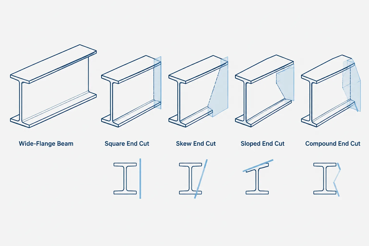
- Copes, clips, notches, and end cuts
- Required part hand
- Clearance from adjacent plates, flanges, stiffeners, or finishes
Do not rely on the apparent scale of a small section symbol. A section may be diagrammatic, and line thickness can hide which face aligns with the controlling dimension. Written orientation information and explicit dimensions should agree with the graphic.
CAD and Model Placement Workflow
Angle profiles imported from a shape library may use the centroid, heel, outside corner, or another point as the insertion origin. Rotation behavior also varies with the profile definition and modeling workflow. Before copying an angle throughout a project, confirm what the profile origin represents.
A dependable workflow is:
- Verify the angle designation against the project shape reference.
- Identify the model or drawing reference point used for placement.
- Rotate the profile to match the required connected leg.
- Check heel and toe direction in an end view.
- Confirm near-side or far-side placement in plan and section.
- Add holes, cuts, and attachments only after orientation is correct.
- Review mirrored copies for handed features.
- Check the finished part against adjacent geometry rather than relying only on centerlines.
For sloped or skewed angles, an end view normal to the member can be especially valuable. It shows the actual cross-section without projection distortion and makes the relationship between the angle and its connection surface easier to verify.
Common Orientation Errors
- Assuming the first listed leg is vertical: The designation lists section dimensions; it does not define installed direction.
- Treating LLV as a connection instruction: LLV identifies rotation but does not necessarily identify the attached leg.
- Ignoring the viewing direction: Near and far sides can reverse when the section arrow or view direction changes.
- Mirroring holes without checking hand: A geometric mirror may create a different fabricated part.
- Modeling sharp inside corners: Real rolled angles include an inside fillet that may affect close-fitting components.
- Locating the angle only by its centroid: Connection fit is usually controlled by physical faces, backs of legs, holes, and clearances.
A Practical Drawing Check
Before releasing an angle detail, imagine the loose angle being held at the connection. Identify the long leg, short leg, heel, both toes, connected surface, and viewing direction. Then compare those features with every plan, elevation, section, and shop view.
If the intended position cannot be reconstructed without guessing, the orientation information is incomplete. LLV and SLV can be efficient notes, but the most reliable details combine them with connected-leg language, directional references, clear views, and dimensions tied to physical surfaces.