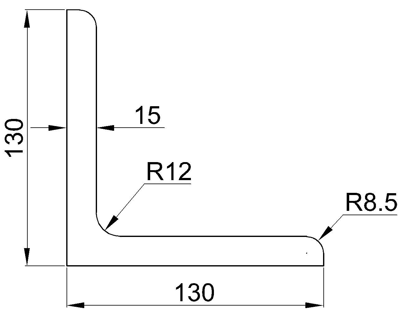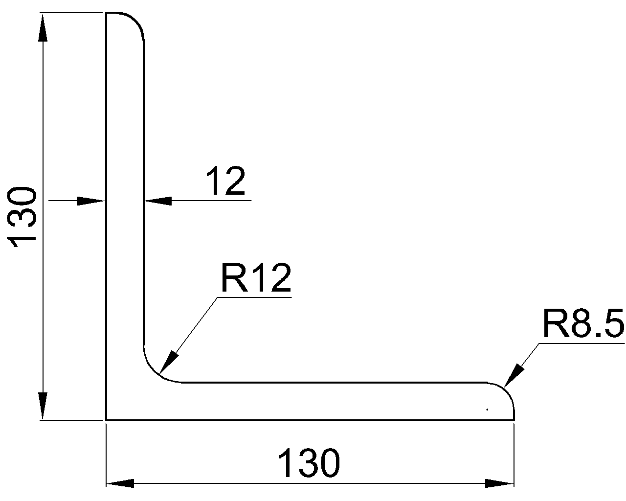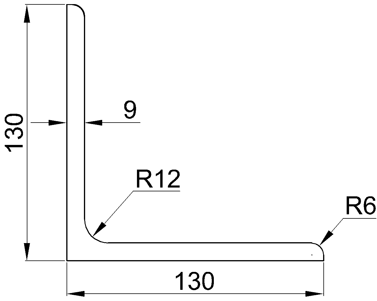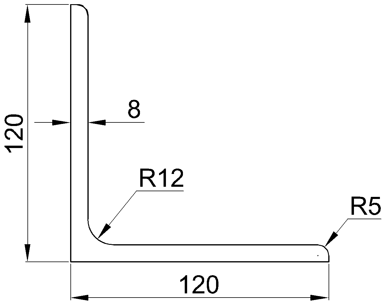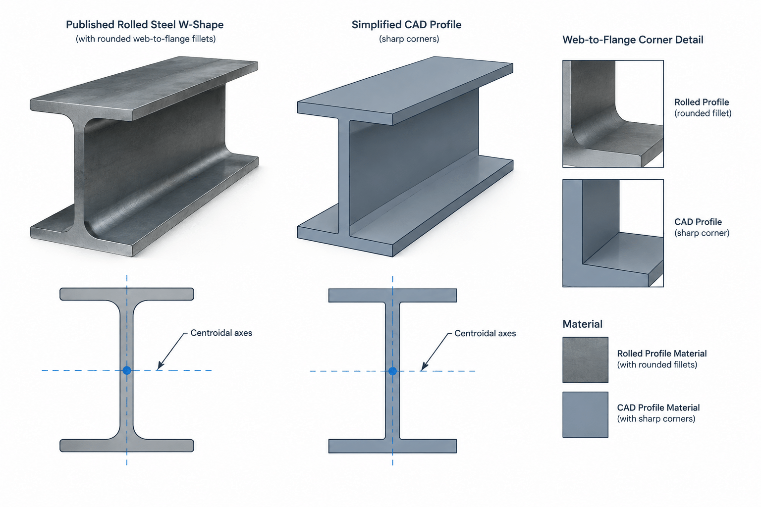
A closed steel profile in CAD can produce area, centroid, and moment-of-inertia values almost instantly. When those results do not match a published shape table, however, the difference is not automatically evidence that the table or software is wrong. It usually means the CAD profile and the tabulated section are based on different geometric assumptions.
This issue commonly appears when drafters reconstruct W-shapes, channels, angles, structural tees, or HSS from a small set of listed dimensions. A profile that looks correct on screen may omit rolled fillets, simplify rounded corners, use rounded dimensions, or place the section on different reference axes. Those apparently minor choices can affect the calculated properties.
The correct response is to identify what each dataset represents, determine which properties are sensitive to the discrepancy, and use the appropriate source for the task.
Published properties and CAD properties answer different questions
Published steel shape tables provide standardized geometric properties for recognized sections. Depending on the shape, these may include gross area, centroid location, moments of inertia, section moduli, radii of gyration, torsional properties, and other reference data. The dimensions and properties are presented with practical rounding and follow the geometric conventions used for that shape series.
A CAD program does something more literal. It calculates properties from the exact boundary selected by the user. If the boundary contains sharp inside corners, approximate arcs, omitted fillets, overlapping lines, or a slightly incorrect wall thickness, the result describes that drawn boundary—not necessarily the published section.
Both results can therefore be internally correct while representing different models.
The most common causes of disagreement
Rolled fillets are missing
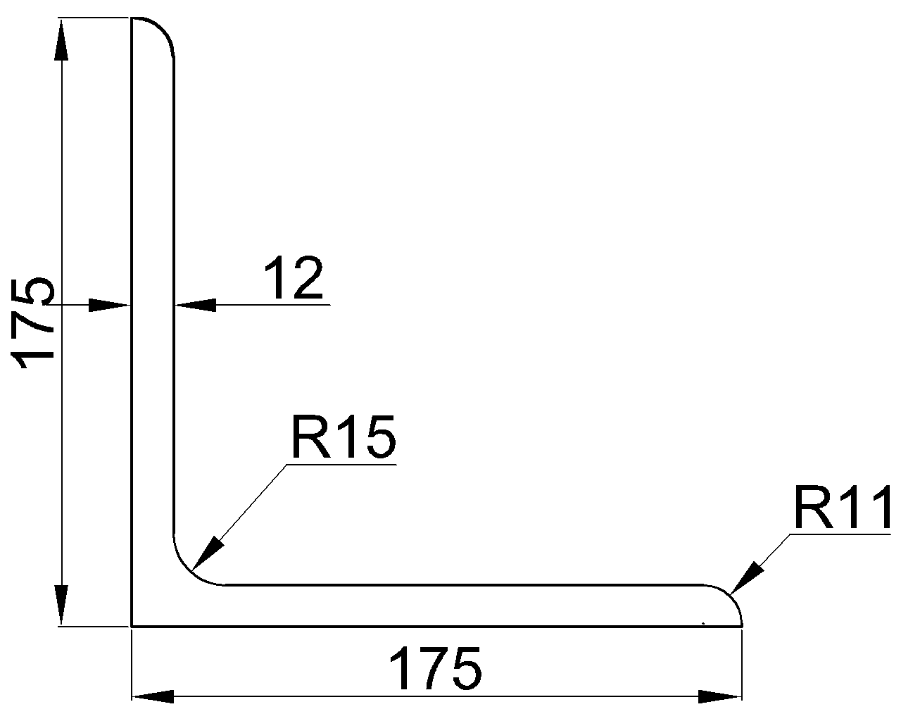
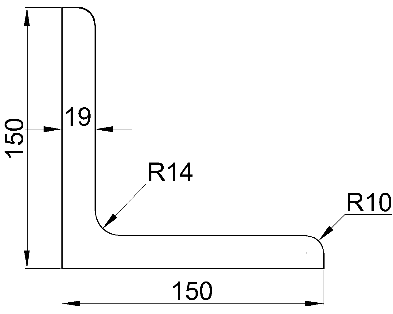
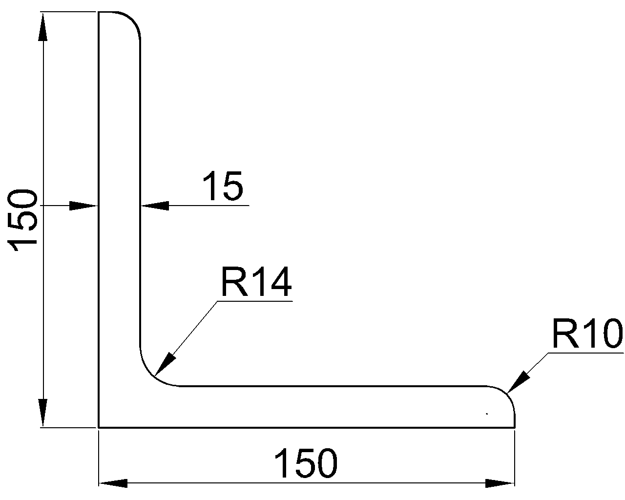
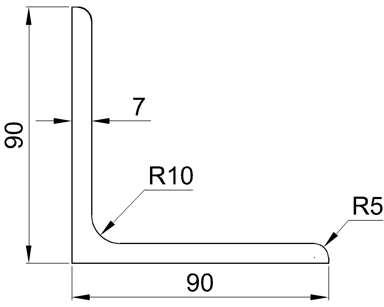
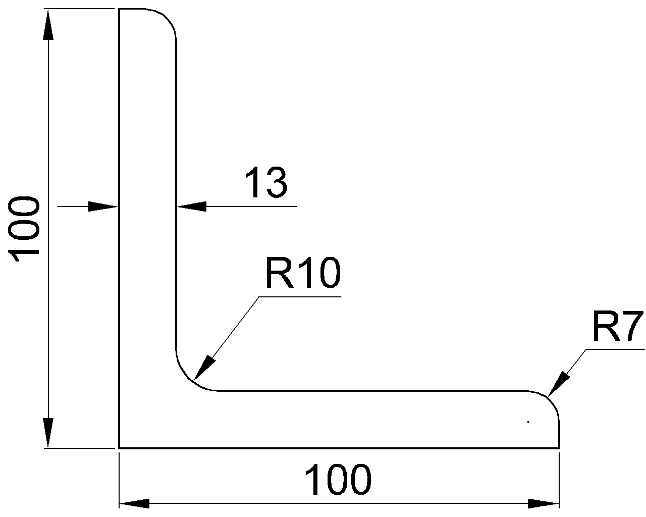
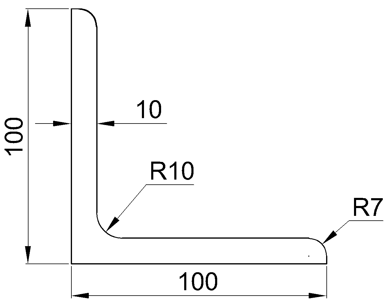
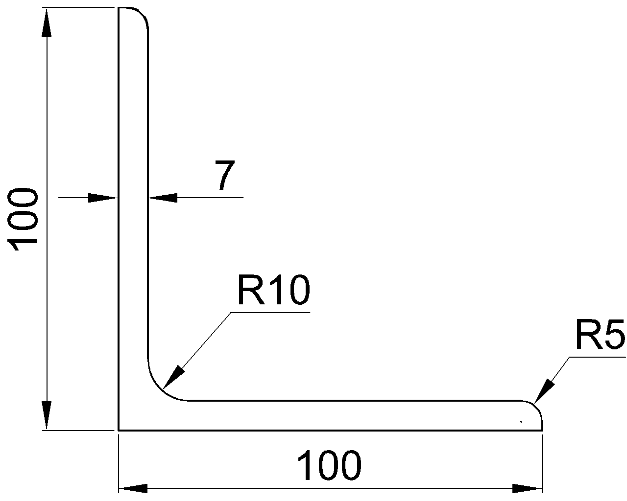
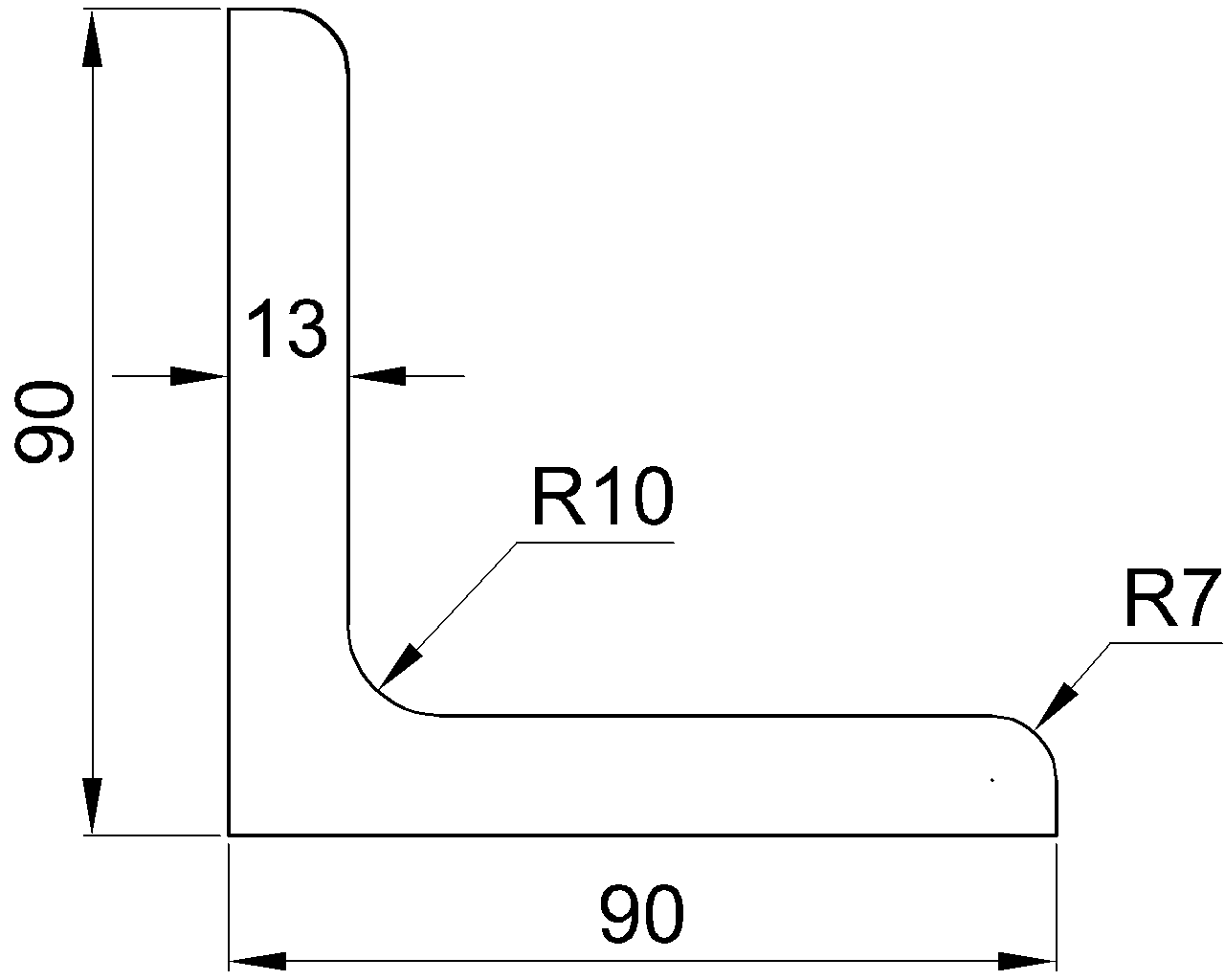
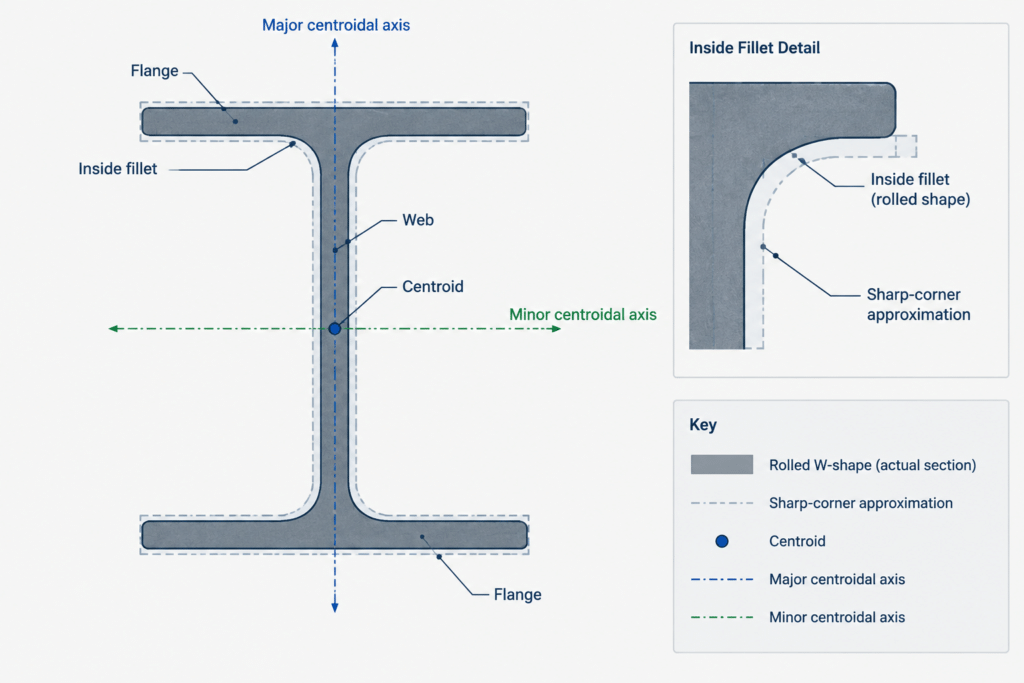
W-shapes, channels, angles, and many other rolled sections do not consist only of flat rectangular plates meeting at sharp corners. Material is present in the rolled fillet regions where adjoining elements meet. A profile assembled from simple web and flange rectangles usually omits this material.
The missing fillets affect gross area and can also affect the centroid and moments of inertia. Their influence on a major-axis inertia may appear modest for some sections, but that does not justify treating the simplified outline as an exact property model. Fillets are especially relevant near connection interfaces, cope boundaries, and other details where physical clearance matters.
Rounded dimensions are treated as exact geometry
Shape tables necessarily display dimensions to a stated level of precision. Reconstructing a profile by treating every displayed value as an infinitely precise manufacturing dimension can create a result that differs from the property basis used for the table.
Several small dimensional differences can accumulate. A slight change in flange width or thickness can noticeably change inertia because the property depends not only on area but also on how far that area lies from the reference axis.
HSS corners are simplified incorrectly
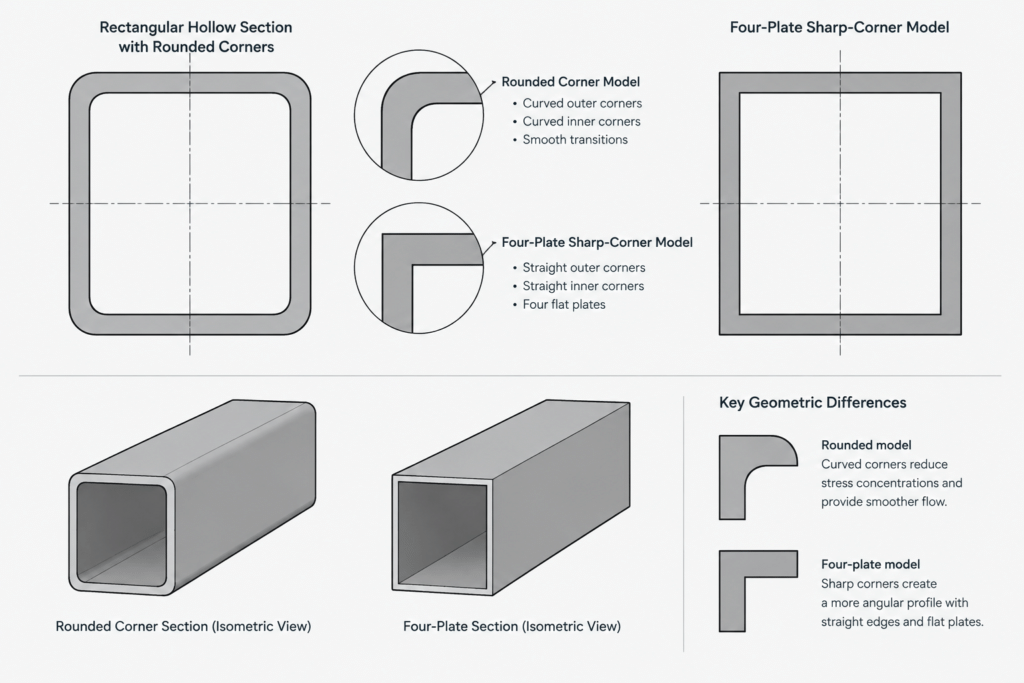
Rectangular and square HSS have rounded exterior and interior corners. A model made from four sharp-cornered plates does not reproduce the same area distribution. Likewise, assigning an arbitrary corner radius simply because the outline looks plausible does not establish a verified section.
HSS modeling also requires care regarding the dimensional and thickness conventions behind the selected reference data. A nominal designation, a listed design thickness, and a measured product are not interchangeable geometric definitions. The reference used for the CAD profile must match the reference used for the properties being checked.
The wrong axis or origin is being compared
CAD software may report properties about the drawing origin, a user coordinate system, or centroidal axes. Shape tables normally identify properties about defined section axes. A comparison is invalid if the axes do not correspond.
This is particularly important for channels, angles, and tees. Their centroid may not lie at the visual center of the bounding box. Angles also have principal axes that are rotated relative to axes parallel to the legs. A CAD result about horizontal and vertical drawing axes should not be compared directly with a property about principal axes.
The outline contains drafting defects
A profile may look closed while still containing duplicate entities, tiny gaps, self-intersections, stacked arcs, or overlapping regions. Region and mass-property tools can reject such geometry or produce unexpected results. Imported and converted files deserve particular scrutiny because splines, polylines, and arcs may have been approximated during translation.
The CAD calculation uses a different property definition
Not every listed section property can be recovered from a generic planar area command. Area, centroid, and planar moments of inertia follow directly from a valid two-dimensional region. Other values may require specialized definitions, assumptions, or analysis procedures.
For example, a polar area moment reported by CAD is not automatically the same as the torsional constant used for structural behavior. Warping properties also cannot be inferred by merely adding the two planar centroidal inertias. Similar symbols or units do not make the quantities interchangeable.
Which properties are most useful for checking a profile?
| Property | What a mismatch may indicate | Checking note |
|---|---|---|
| Gross area, A | Missing fillets, incorrect wall thickness, bad corners, or an incomplete boundary | Often the best first check because it tests the total enclosed material |
| Centroid | Asymmetry, incorrect orientation, omitted material, or the wrong reference origin | Confirm both axis directions and the datum used |
| Moment of inertia, I | Incorrect dimensions, misplaced material, or comparison about different axes | Material farther from the axis has a larger influence |
| Section modulus, S | An inertia or extreme-fiber-distance discrepancy | Check the relationship between inertia and the applicable extreme distance |
| Radius of gyration, r | An area or inertia mismatch | Because r is derived from I and A, it is not an independent geometry check |
| Torsional or warping property | Different definitions or an unsuitable CAD calculation | Use an appropriate structural reference or verified section-analysis method |
A practical validation workflow
- Identify the intended use. Decide whether the profile is for visual drafting, interference checking, connection detailing, fabrication geometry, or independent section analysis. The necessary geometric fidelity depends on that purpose.
- Confirm the designation and source. Make sure the CAD file and the table refer to the same shape, orientation, and dimensional convention. Do not select a section merely because its nominal depth appears similar.
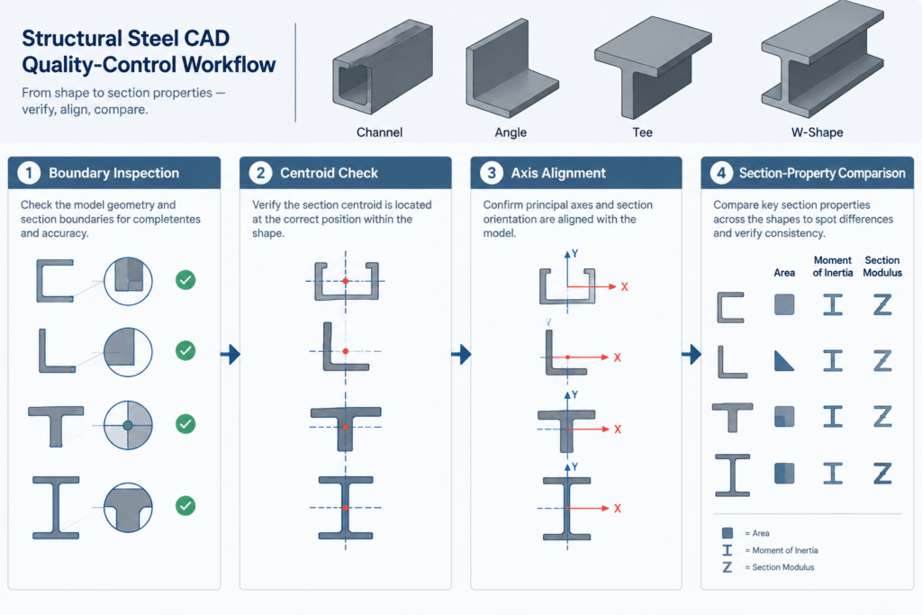
- Inspect the boundary. Check flanges, webs, legs, walls, fillets, corner radii, and open ends. Verify that there is one valid material region without accidental overlaps or voids.
- Set consistent axes. Move or transform the profile only after recording its original reference point. Compare centroidal properties about axes that correspond to those in the table.
- Compare area first. A meaningful area discrepancy usually indicates that the boundary model itself differs. Correct that issue before investigating derived properties.
- Compare centroid and inertia next. For an asymmetric section, verify the centroid in both directions. Then compare the applicable moments of inertia using matching axes.
- Review derived values. If area and inertia agree appropriately, values derived from them should be checked using consistent definitions and extreme-fiber distances.
- Document the model basis. Note whether the file is a simplified drafting profile, a dimension-based reconstruction, or a profile validated against a recognized dataset. This prevents later users from assuming greater accuracy than the file provides.
When a simplified profile is acceptable
A simplified outline can be useful for general arrangement drawings, schematic sections, member orientation diagrams, and some clash-detection tasks. It may also keep files lighter and make snapping easier. In these uses, a clean representation can be more practical than a highly detailed rolled contour.
The limitation should be explicit. A sharp-cornered W-shape assembled from rectangles should not silently become the basis for connection clearance, automated weight takeoff, or section-property calculations. A centerline stick model should not be treated as a physical envelope, and a nominal HSS outline should not be assumed to represent exact corner geometry.
When the published table should remain the governing reference
For engineering properties of a recognized structural shape, use the applicable verified shape data rather than replacing it with values from an unvalidated drawing. CAD calculations are valuable as quality-control tools, but agreement depends on reconstructing the same geometric model and using the same property definitions.
If a member is custom-built, altered, perforated, reinforced, coped, or otherwise outside the published gross-section geometry, a separate calculation may be needed. That calculation should model the actual question being investigated and should not be presented as a standard rolled-shape property.
A useful rule for CAD libraries
Every steel profile library should distinguish between representation geometry and analysis geometry. Representation geometry supports drawings and coordination. Analysis geometry is constructed and verified for property calculations. Sometimes one profile can serve both purposes, but that should be demonstrated rather than assumed.
When CAD-calculated steel section properties differ from a table, start with geometry, axes, and definitions—not decimal precision. A visually small modeling choice can explain the discrepancy, while adding more decimal places to an approximate profile only makes the approximation look more authoritative.