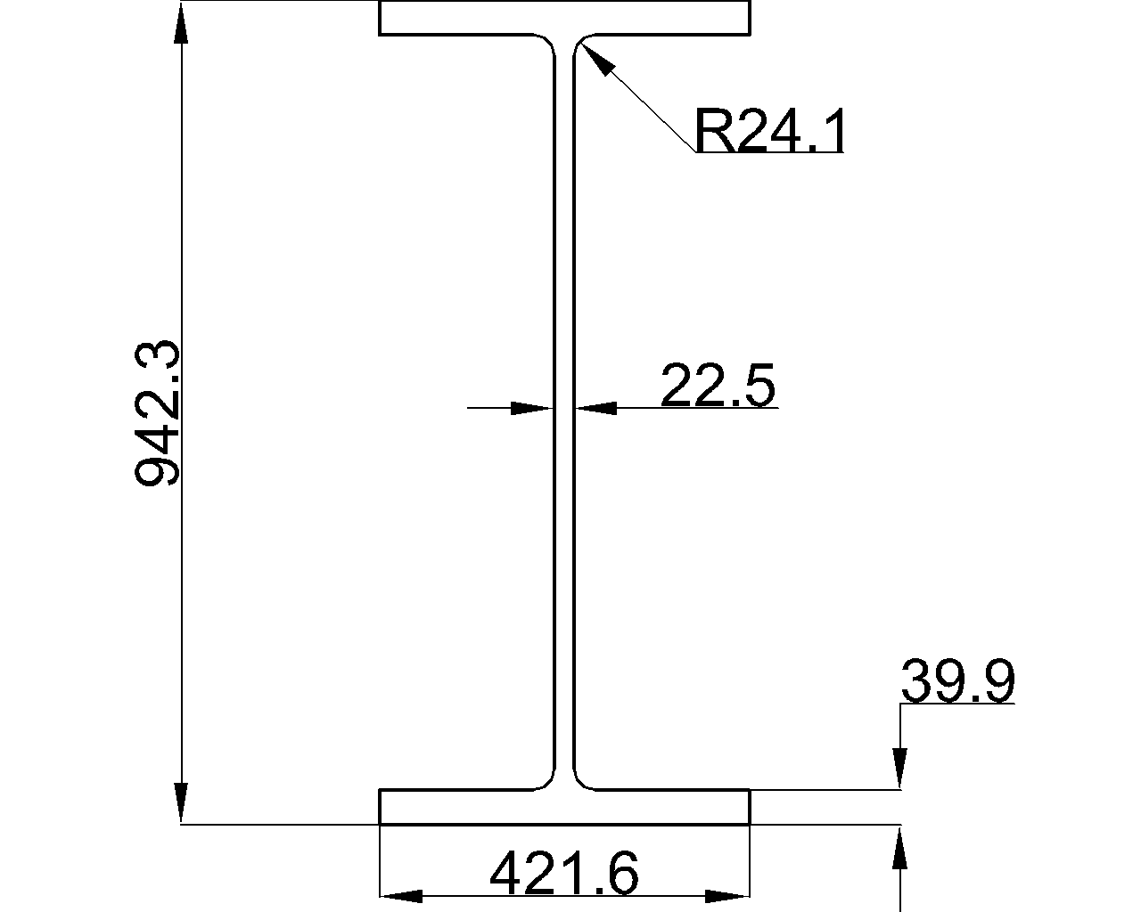
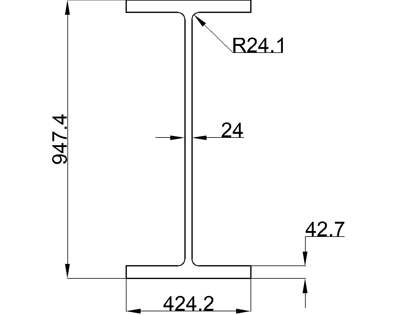
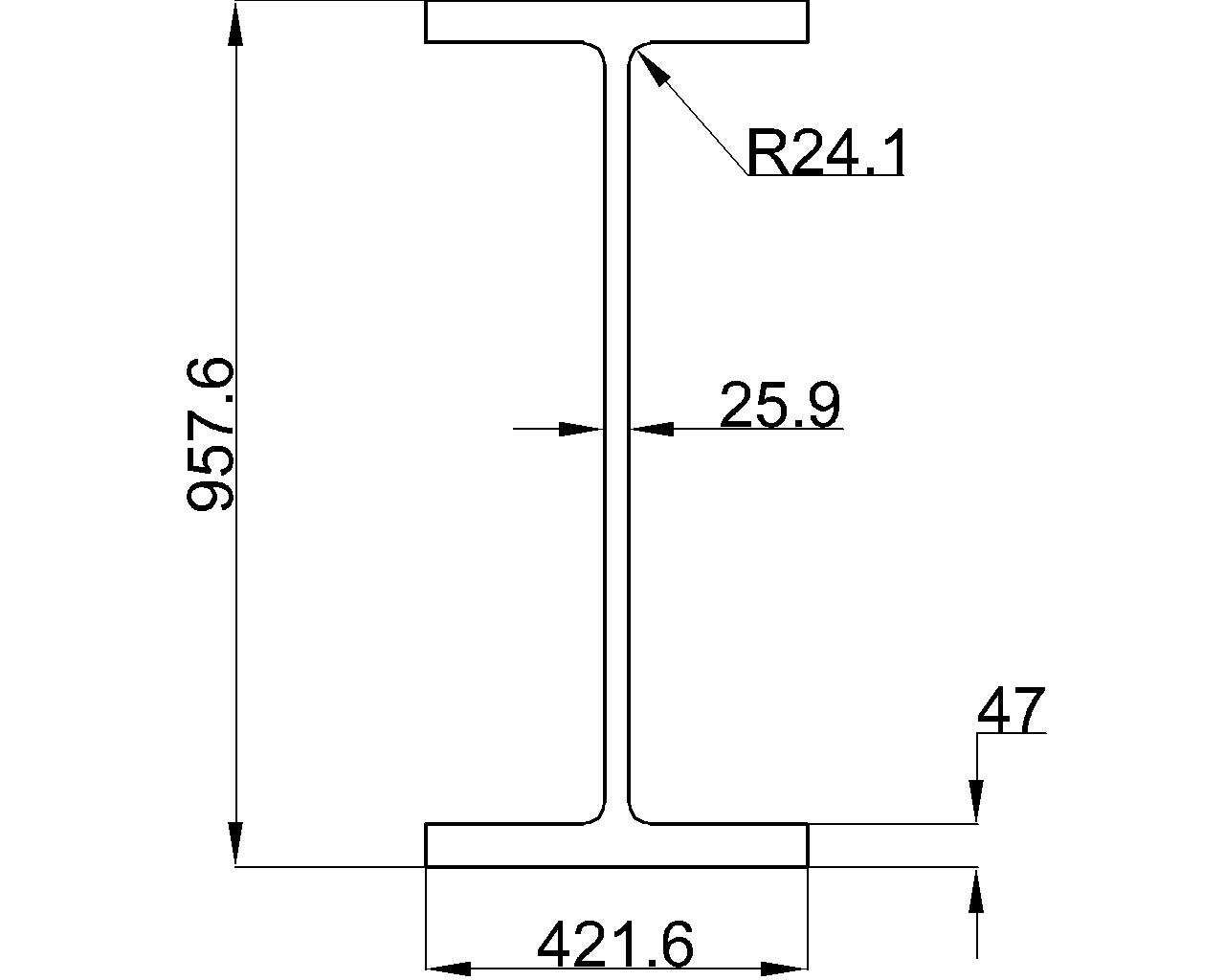
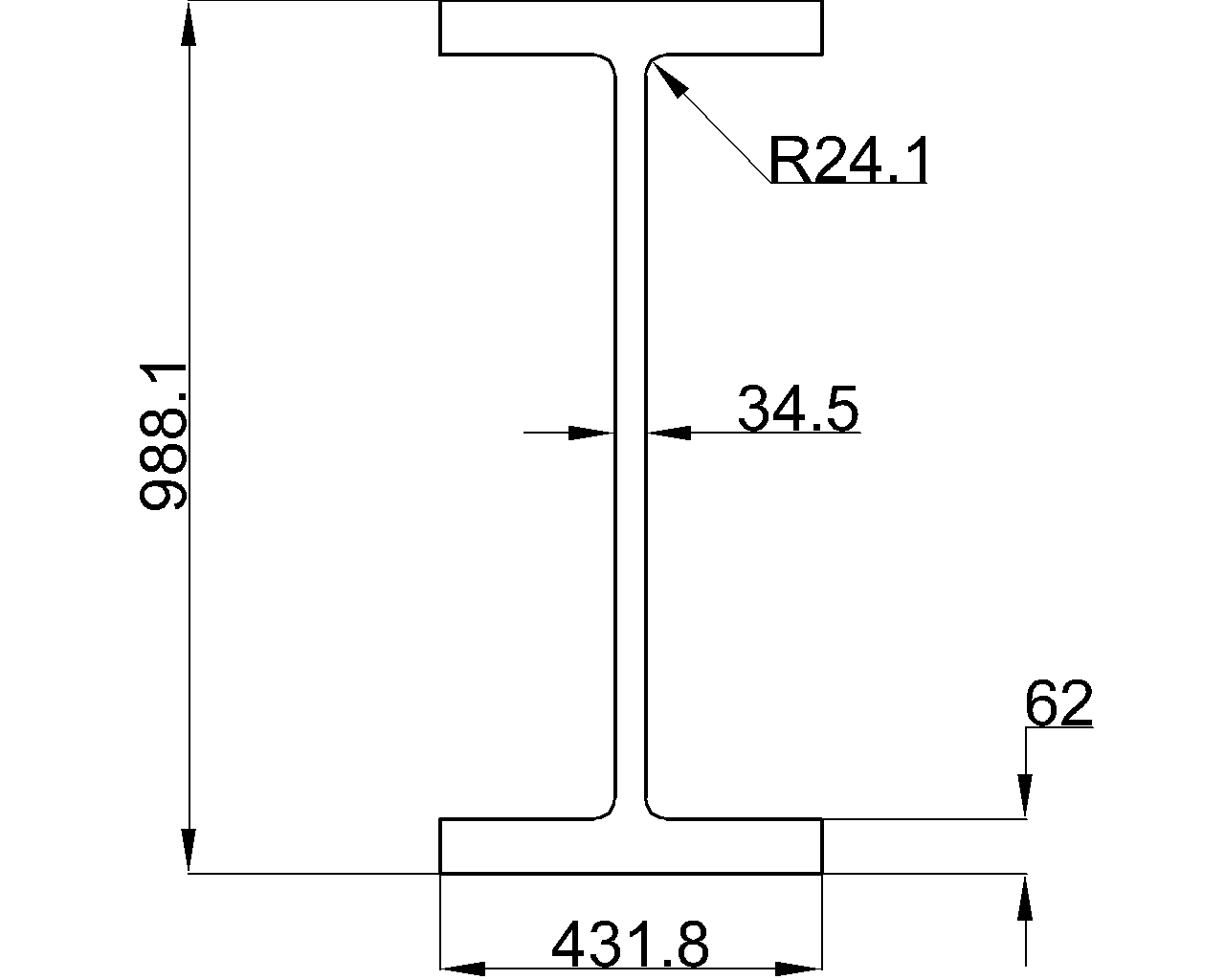
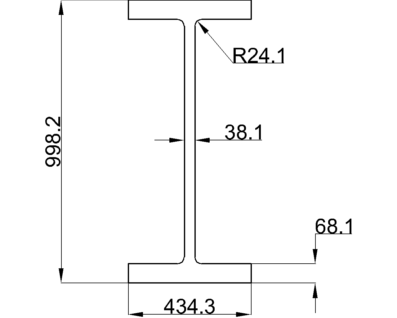
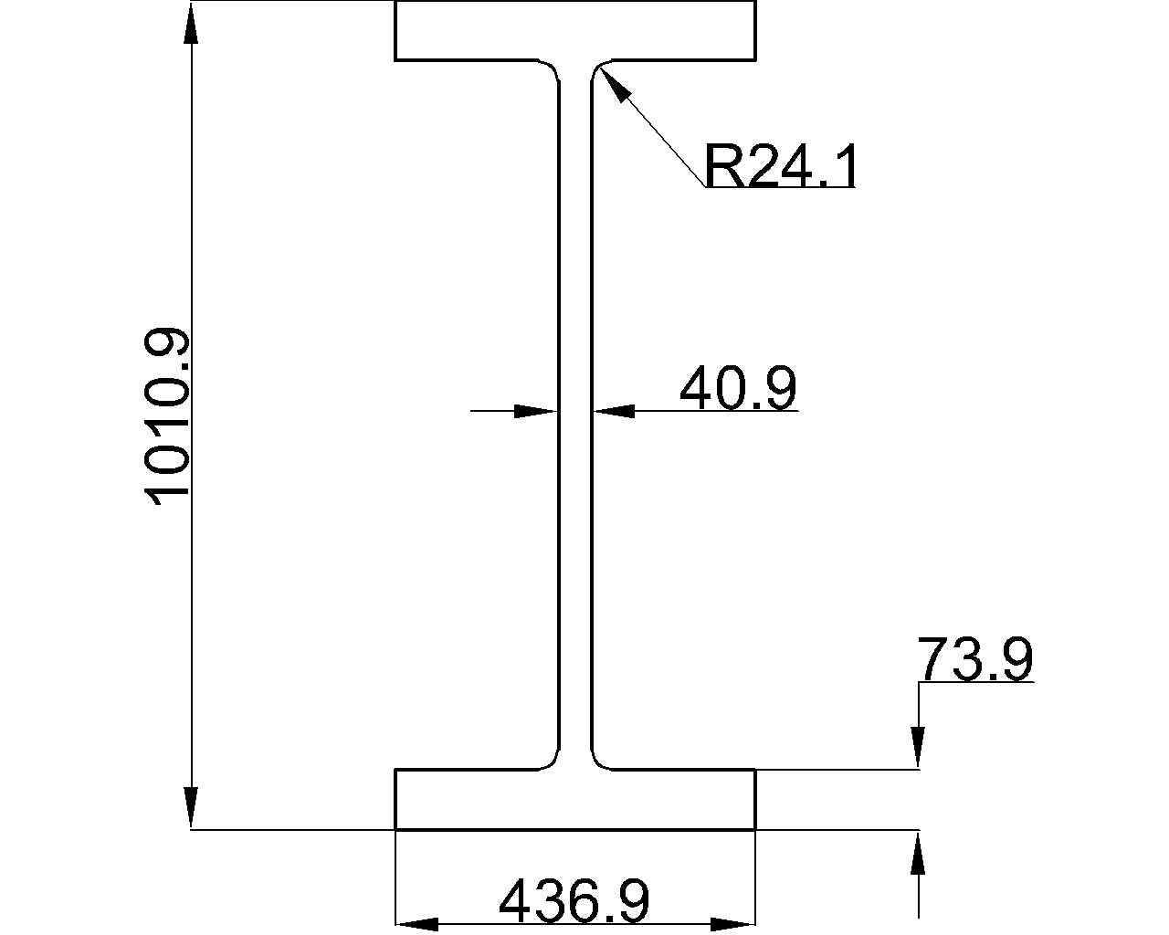
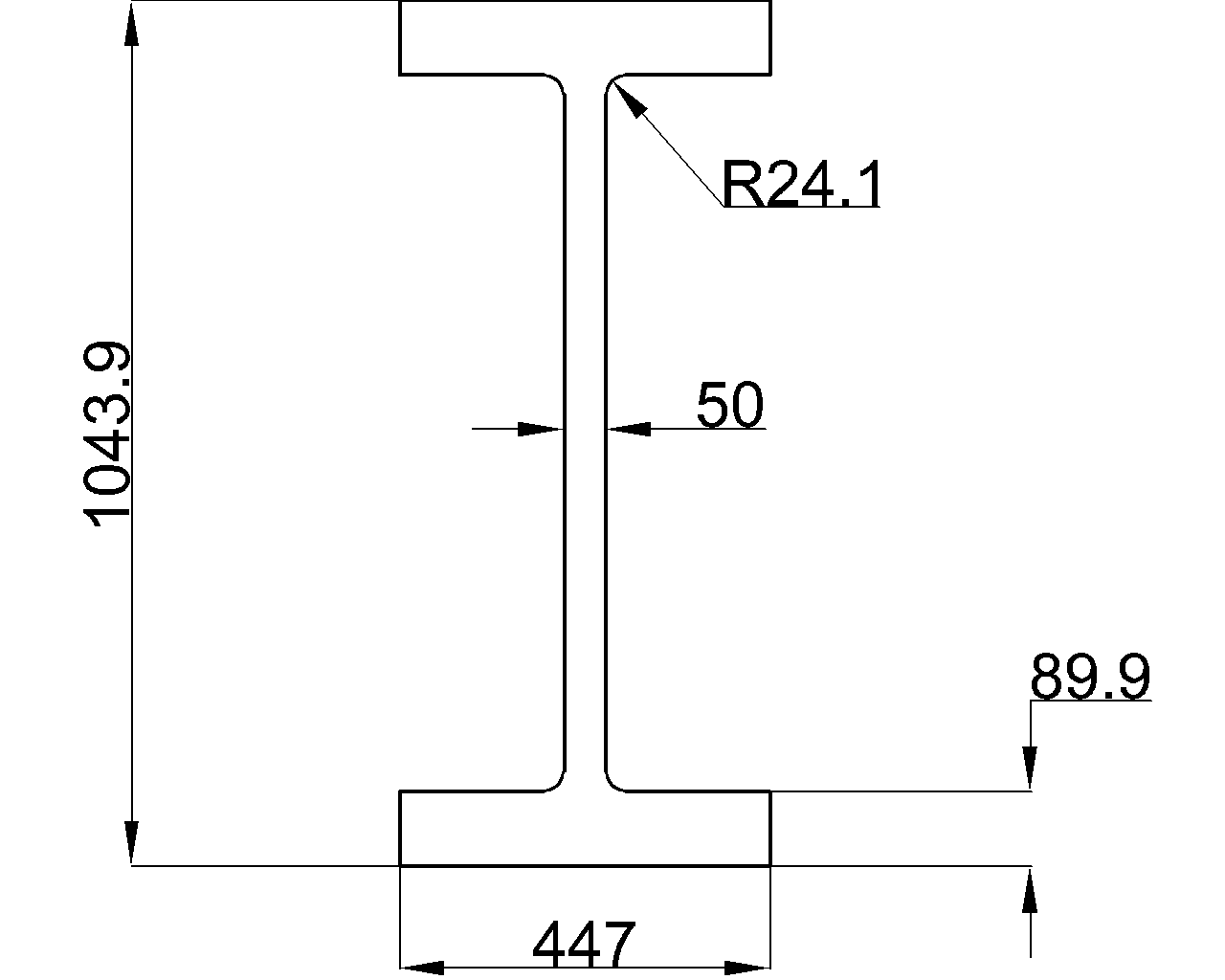
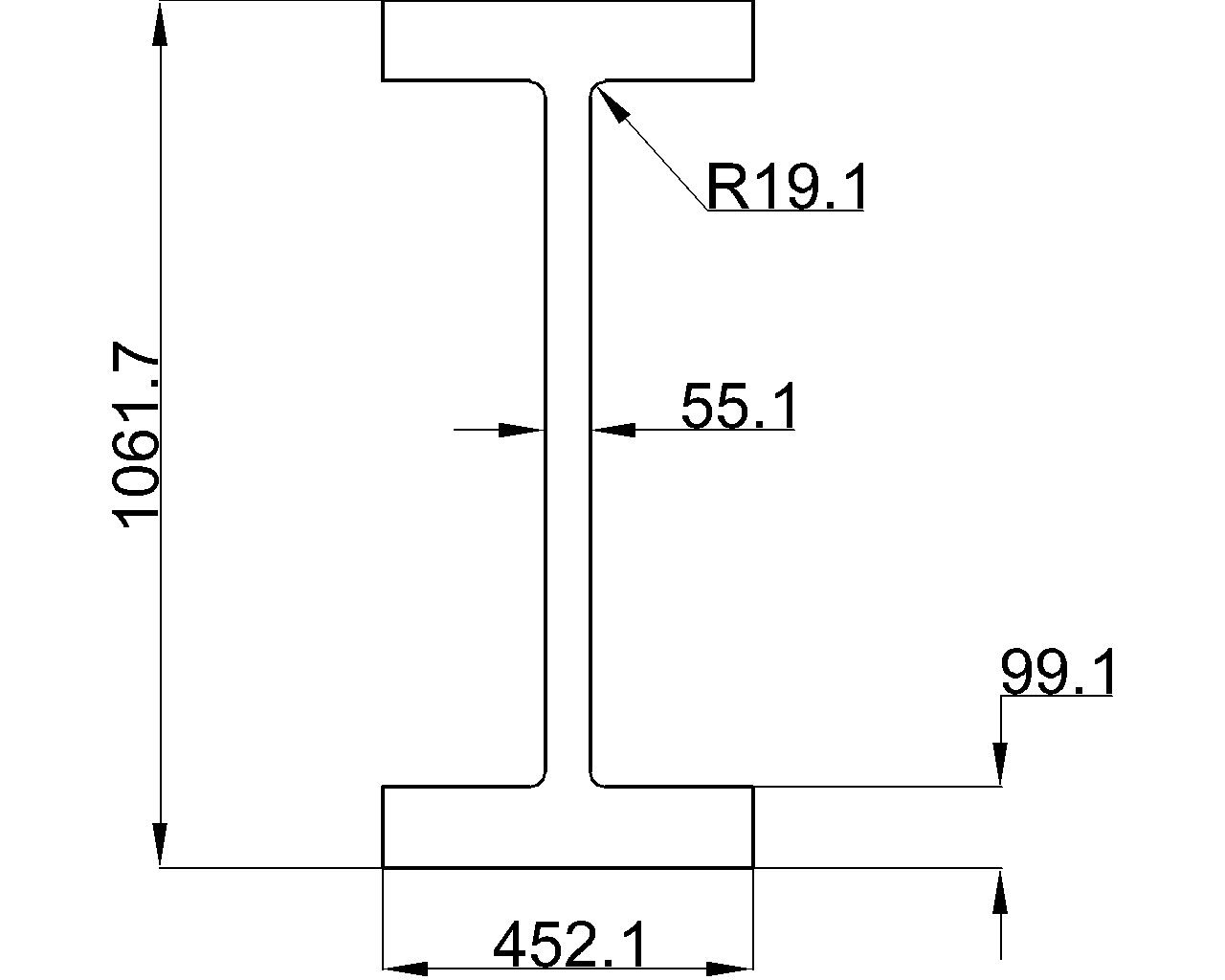
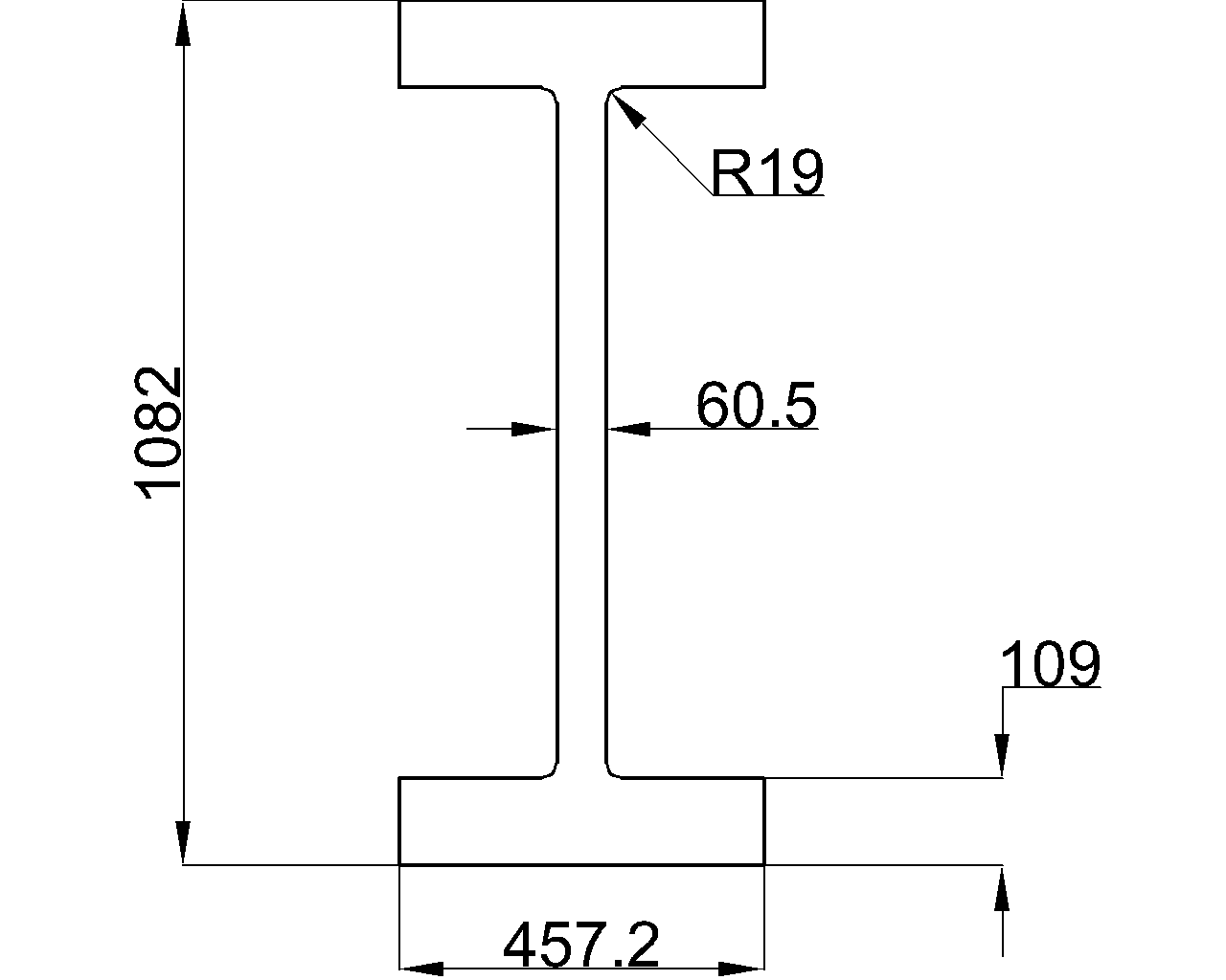
The W30x235 reference provides the published geometric and mass-related properties needed to identify this W-shape in steel design, detailing, estimating, and CAD workflows. Use the numeric information below as the controlling local reference for this page.
For broader comparison, pair this page with related resources on W-shape dimensions, steel section properties, steel connections, and CAD/DWG steel-shape references. Those topics help place an individual shape within a larger structural steel workflow without replacing project-specific engineering review.
W Beam
refer to : AISC 16
the American Institute of Steel Construction (AISC) Specification for Structural Steel Buildings (AISC 360-16), which is the 2016 edition of the AISC Specification for Structural Steel Buildings. It provides guidelines and requirements for the design, fabrication, and erection of steel structures in the United States.
Depth : 795 mm
Width : 383.5 mm
Web Thickness : 21.1 mm
Flange Thickness : 38.1 mm
Root Fillet Radius : 20.1 mm
Sectional Area : 447.1 cm2
Unit Weight : 351 kg/m
How to read the W30x235 reference
The listed dimensions describe the overall depth and width of the shape, along with the web thickness, flange thickness, and root fillet radius. These values are useful when checking clearances, modeling the section, preparing connection details, or comparing the shape with other W-shape references.
The sectional area is a geometric property of the cross-section, while the unit weight supports material takeoffs and preliminary weight estimates. Neither value should be treated as a substitute for the complete design checks required for a specific member, connection, limit state, or loading condition.
AISC reference and engineering use
This page identifies AISC 360-16 as its reference for structural steel building requirements. Designers and detailers should confirm that the governing project specification, adopted code, material requirements, fabrication provisions, and applicable edition are consistent with the project before using the section in design or documentation.
Using the W30x235 DWG file
The downloadable DWG resource can support drafting, layout, and coordination. Before inserting it into a production drawing, verify drawing units, insertion scale, layer behavior, orientation, and the file’s correspondence with the section data shown on this page. CAD geometry is a drafting aid and should be checked against the controlling engineering reference.
Related reference topics
- Compare W-shape dimensions and section-property terminology.
- Review steel connection and detailing concepts before developing fabrication drawings.
- Use CAD and DWG reference resources as starting points for coordinated project documentation.
W30x235 FAQ
What information is listed for the W30x235?
The reference lists the shape type, AISC reference, overall dimensions, web and flange thicknesses, root fillet radius, sectional area, and unit weight.
What do the depth and width values describe?
Depth describes the overall vertical extent of the section, while width describes its overall horizontal extent. These dimensions are commonly used for layout, clearance checks, and CAD representation.
Why are web thickness, flange thickness, and root fillet radius important?
They describe key parts of the cross-sectional geometry. Together, they help with accurate modeling and with coordination around connections, copes, supports, and adjoining members. The applicable design checks still require project-specific engineering.
What is the sectional area used for?
Sectional area is a geometric property used in section-property review and material-related calculations. Its appropriate application depends on the governing design method and load case.
Can the DWG file be used directly for fabrication?
Use the DWG as a drafting reference, not as an unchecked fabrication document. Confirm units, scale, geometry, project requirements, and coordination with the engineer’s design information before issuing drawings.