The W10x26 is a W beam profile used as a reference shape in structural steel detailing and design workflows. This page provides the published profile dimensions, sectional area, unit weight, and a downloadable DWG resource in one place.
Use the data below when reviewing framing layouts, comparing steel shapes, or preparing preliminary CAD details. Final member selection and connection design require project-specific engineering verification.
W Beam
refer to : AISC 16
the American Institute of Steel Construction (AISC) Specification for Structural Steel Buildings (AISC 360-16), which is the 2016 edition of the AISC Specification for Structural Steel Buildings. It provides guidelines and requirements for the design, fabrication, and erection of steel structures in the United States.
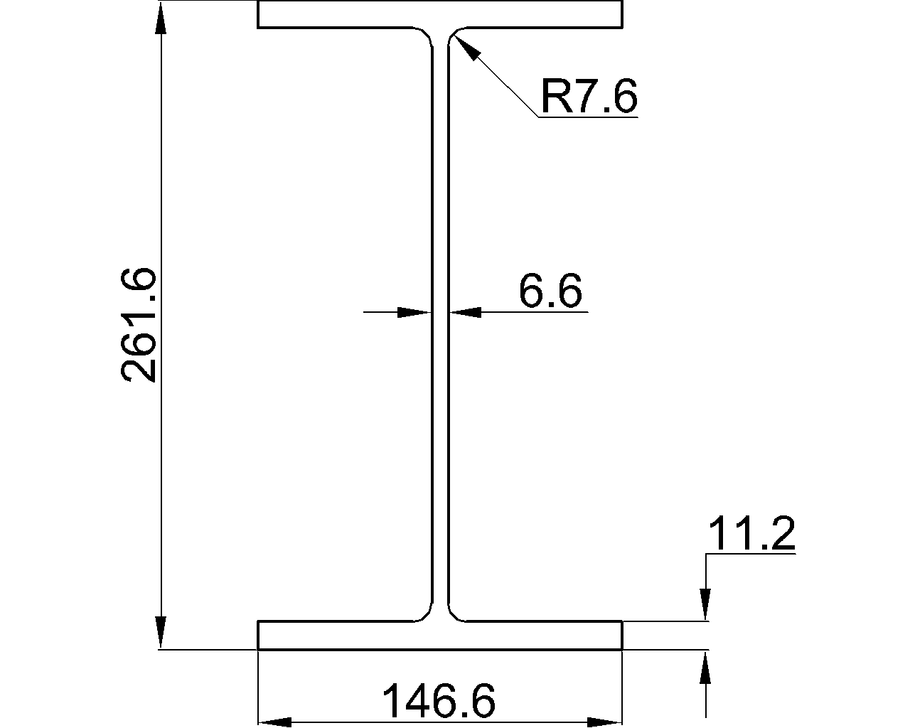
Depth : 261.6 mm
Width : 146.6 mm
Web Thickness : 6.6 mm
Flange Thickness : 11.2 mm
Root Fillet Radius : 7.6 mm
Sectional Area : 49.1 cm2
Unit Weight : 38.5 kg/m
How to read the W10x26 reference
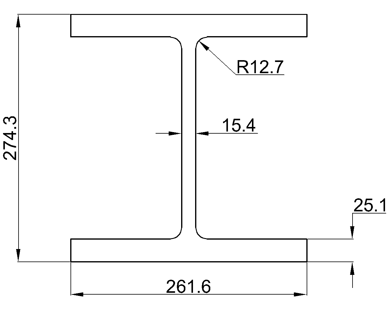
The source data identifies the overall depth and flange width, followed by the web and flange thicknesses. These dimensions help describe the cross-sectional geometry of the shape and support coordination between structural calculations, drawings, and fabrication details.
The root fillet radius describes the transition between the web and flange. This area is important when checking clearances, fitting connection components, or interpreting a CAD section. The listed sectional area and unit weight are reference properties for material quantity checks and shape comparison; they should not be treated as a substitute for the governing project design requirements.
AISC reference and design context
The page cites the American Institute of Steel Construction Specification for Structural Steel Buildings, identified in the source as AISC 360-16. That specification provides requirements related to the design, fabrication, and erection of steel structures in the United States. Engineers should confirm the applicable project specification, material requirements, load combinations, connection assumptions, and local adoption before using any shape data for design.
Using the DWG resource
The downloadable W10x26 DWG can support drafting, section-library development, layout coordination, and preliminary detailing. Confirm units, insertion scale, layer standards, and drawing orientation before incorporating the file into a production document. A CAD outline represents geometry; it does not by itself establish design capacity, connection adequacy, or fabrication tolerances.
Related steel-shape references
Readers comparing this profile may also benefit from related references covering W-shape terminology, steel section properties, structural steel connections, steel detailing practices, and DWG resources for steel shapes. These topics provide useful context when moving from a section reference to a coordinated structural drawing.
Frequently asked questions
What type of section is the W10x26?
It is identified in the source as a W beam, commonly understood as a wide-flange structural steel shape.
What information is listed for this profile?
The reference includes depth, width, web thickness, flange thickness, root fillet radius, sectional area, and unit weight.
What does the AISC reference mean?
The page references AISC 360-16, the American Institute of Steel Construction specification identified in the source for structural steel building design, fabrication, and erection requirements.
Can the DWG file be used directly for structural design?
The DWG is a drafting and geometry reference. It should be checked for units and project standards, and it does not replace engineering checks for member strength, stability, connections, or detailing.
Are the listed dimensions sufficient for member selection?
No. Member selection depends on the applicable loads, span and restraint conditions, material requirements, limit states, connections, serviceability criteria, and project specifications. A qualified engineer should verify the complete application.