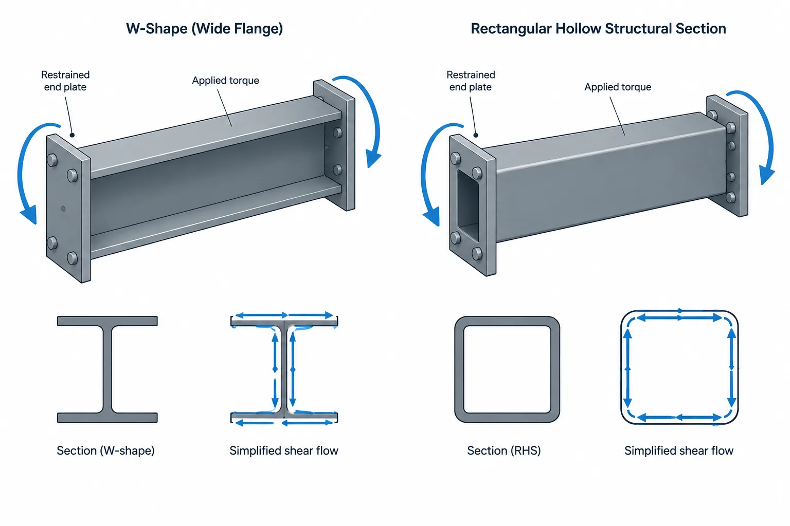
W-shapes and hollow structural sections can both carry bending, axial force, and shear, but they behave very differently when a load tends to twist the member. The difference is not simply that one shape is stronger than another. It comes from the section geometry, the location of the applied load, the freedom of the member ends to warp, and the way connections introduce or restrain torsion.
This comparison helps explain why replacing a W-shape with an HSS—or the reverse—requires more than matching area, depth, weight, or bending properties. Torsional behavior and connection load paths must also be reconsidered.
Why cross-section geometry matters in torsion
A W-shape is an open section. Its flanges and web do not form a continuous enclosure around an internal area. Rectangular, square, and round HSS are closed sections because their walls create a continuous path around the section.
That geometric distinction has a major effect on how torsional shear can flow through the member. In a closed section, shear can circulate around the perimeter. In an open section, the shear path cannot circulate in the same way and the section generally develops greater twist for a comparable torsional demand and member configuration.
This does not mean that every HSS member is automatically satisfactory for every torsional load. Wall slenderness, local connection effects, section distortion, member length, support conditions, and combined forces still matter. It does mean that closed HSS geometry is generally more efficient for resisting Saint-Venant torsion than open W-shape geometry.
Saint-Venant torsion and the torsional constant J
The torsional constant, commonly shown as J in section-property tables, is used in evaluating uniform or Saint-Venant torsion. It is a geometric property, not a torque capacity by itself. Torsional stiffness also depends on the material shear modulus and the member length.
For a member subject primarily to uniform torsion, the product commonly associated with torsional rigidity includes the shear modulus and J. A larger J generally indicates greater resistance to twist when the other relevant conditions are the same.
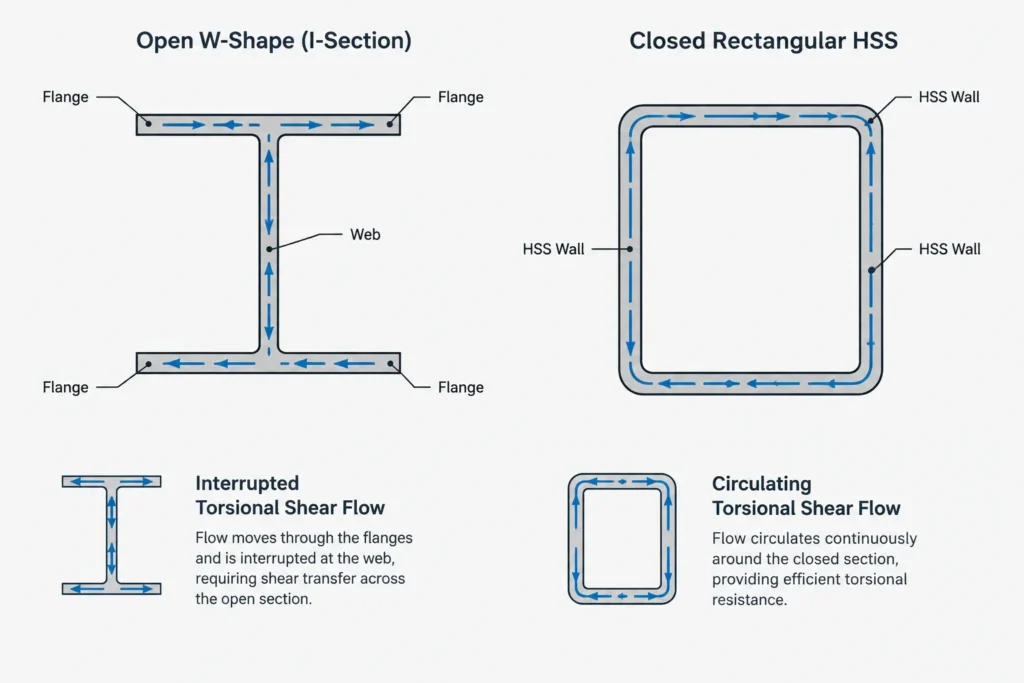
Closed HSS commonly have much more favorable Saint-Venant torsional behavior than open W-shapes of broadly comparable scale. Shape tables make this contrast visible, but table values should be compared only after confirming consistent units, axis conventions, section definitions, and data sources.
Designers and detailers should not use J as if it were a standalone allowable torque. The actual response can include warping, local wall effects, connection deformation, stress concentrations, and interaction with bending or shear.
Why warping is important for W-shapes
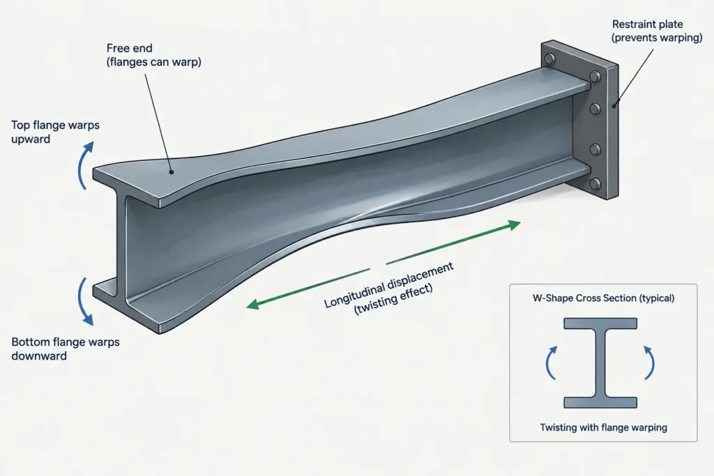
When a W-shape twists, its flanges tend to move longitudinally in opposite patterns. This behavior is called warping. If the member is free to warp, the response differs from that of a member whose flange movement is restrained by end plates, framing, diaphragms, slabs, bracing, or other attachments.
Restraining warping can generate longitudinal stresses and additional forces at the restraint. These effects are not represented by a simple torque-and-rotation check based only on J. The warping constant Cw is one of the section properties used when evaluating nonuniform torsion and warping behavior in open sections.
Warping restraint is not automatically beneficial or harmful. Restraint may reduce twist while creating forces that must be transferred through the flanges and connections. The critical issue is whether the analysis model and connection details represent the same physical restraint condition.
Common sources of unintended warping restraint
- End plates connected across both flanges and the web
- Floor systems attached to one or both flanges
- Transverse beams framing into the member
- Web stiffeners, diaphragms, or cross-frames near the member end
- Rigid attachments modeled as simple supports, or simple details modeled as fully fixed
On drawings, it may not be enough to show only a torque reaction. The receiving connection needs a recognizable load path for the associated flange forces, web forces, welds, bolts, plates, and supporting components.
How closed HSS carry torsion
In a closed HSS, torsional shear can flow around the perimeter. This makes square, rectangular, and round HSS attractive where torsion is an important part of the member behavior, such as cantilevered supports, offset framing, equipment frames, canopies, and members supporting eccentric attachments.
Round HSS have rotationally symmetric section geometry, so their basic geometric response does not depend on rotating the cross-section about its longitudinal axis. Rectangular HSS still have distinct major- and minor-axis bending properties, even though the wall forms a closed torsional path.
The closed shape also changes the connection problem. A force applied to one HSS wall must enter the section and distribute through the walls. Concentrated attachments can cause local wall bending, deformation, or distortion even when the overall member has favorable torsional stiffness. Reinforcement, diaphragms, through-plates, or other connection components may be needed when established by the project design.
Side-by-side behavior
| Topic | W-shape | HSS |
|---|---|---|
| Section type | Open | Closed |
| Uniform torsion | Often relatively flexible in twist | Generally efficient because shear can circulate around the perimeter |
| Warping | Can be a major part of member response | Usually less dominant in ordinary member-level comparisons, though local and distortional effects remain possible |
| Connection access | Flanges and web are externally accessible | Interior access may be limited or unavailable |
| Concentrated attachment effects | May create flange bending, web effects, and warping forces | May create local wall deformation and section distortion |
| Useful table properties | J, Cw, bending properties, and section dimensions | J, bending properties, wall and corner geometry, and section dimensions |
The table describes general behavior, not a substitution rule. A particular W-shape can be suitable for torsional loading when properly analyzed and detailed, while a particular HSS can be unsuitable because of local connection demands, slender walls, excessive rotation, or other governing conditions.
Load position and the shear center
Torsion can arise even when no torque is explicitly listed on the drawings. A transverse force that does not pass through the section’s shear center creates a twisting tendency.
For a doubly symmetric W-shape, the shear center coincides with the centroid in the idealized section. Loads applied above a flange, from an offset bracket, or through one side of the member can still be eccentric to that point. The resulting torque depends on both the force and its perpendicular offset.
For a symmetric HSS, the centroid and shear center also coincide in the idealized section. However, an attachment welded to one wall or positioned beyond the member face can introduce local effects and torsion before the load becomes distributed through the full section.
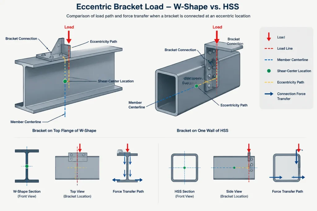
CAD and analysis models often place line members at their centroidal axes. Physical loads, plates, joists, rails, and brackets may act at member faces instead. Those offsets should not disappear simply because the analytical member is represented by a single centerline.
Connection effects that can control the choice
A section with favorable member-level torsional stiffness still needs a connection capable of delivering the torque. This is often where a W-shape-to-HSS comparison becomes project-specific.
W-shape connection considerations
- Determine whether torque is transferred through flange forces, web forces, or a combination.
- Identify whether the connection restrains warping or permits some flange movement.
- Check access for bolts, welds, stiffeners, and flange-connected components.
- Coordinate lateral bracing and attachments that change the restraint condition.
HSS connection considerations
- Identify how force enters the individual wall and spreads into the closed section.
- Check whether interior access is required for bolts, backing, or welding.
- Coordinate through-plates, diaphragms, cap plates, or local reinforcement where specified by the design.
- Do not assume that the full HSS torsional resistance is engaged immediately at a flexible wall attachment.
The connection should be evaluated as part of the torsional load path, not added after the member has been selected solely from a shape table.
CAD and analysis workflow
- Locate the real load line. Model or dimension the actual point, face, or bracket where the force acts.
- Confirm the member reference axis. Determine whether the model line represents the centroid, a face, a flange surface, or another insertion point.
- Calculate the physical eccentricity. Include offsets created by plates, seats, brackets, and framing geometry.
- Identify the section model. Verify whether the software uses open-section warping behavior, simple beam torsion, shell elements, or another idealization.
- Review end restraint. Compare modeled releases and restraints with the actual connection geometry.
- Inspect local load introduction. Member-level torsion results do not automatically capture HSS wall deformation or localized W-shape flange and web effects.
- Coordinate drawings and reactions. Show sufficient information for the connection designer and detailer to understand torque direction, load location, and restraint assumptions.
What to recheck when changing section type
Changing from a W-shape to HSS is not just a geometric cleanup, and changing from HSS to a W-shape is not just a connection-access improvement. Recheck:
- Torsional stiffness and expected rotation
- Uniform torsion versus warping-sensitive behavior
- Major- and minor-axis bending properties
- Combined axial, bending, shear, and torsional effects
- Local wall, flange, and web behavior at attachments
- Connection access, weld sequencing, and inspection access
- End restraint and bracing assumptions
- Member insertion points, face offsets, and overall envelope
- Fabrication, drainage, coating, and closure requirements for HSS
Practical takeaway
HSS generally provide an efficient closed path for torsional shear, while W-shapes require greater attention to twist, warping, and restraint. That broad distinction is useful during early member selection, but it is not a complete design conclusion.
The most reliable workflow is to trace the load from its actual point of application, identify the eccentricity to the shear center, select an analysis model that represents the section and restraints, and then detail a connection capable of transferring the resulting forces. Shape-table properties such as J and Cw support that process, but they must be interpreted together with member geometry, connections, and the physical load path.