The UB 457x152x74 is a Universal Beam reference entry for engineers, detailers, fabricators, and students working with structural steel information. This page brings together the source dimensional data, section-property information, standard reference, and downloadable CAD resource in one location.
Use the designation as a starting point when identifying the section, then use the listed dimensions and properties for drawings, schedules, connection detailing, and preliminary reference checks. Final member selection and design should be verified against the applicable project requirements and engineering calculations.
UB 457x152x74
Universal Beams
refer to : EN 10365:2017
a European standard that defines the dimensions, tolerances, and sectional properties for hot-rolled steel channels, I-beams, and H-beams used in construction and engineering. It ensures uniformity and compatibility across European structural steel products.
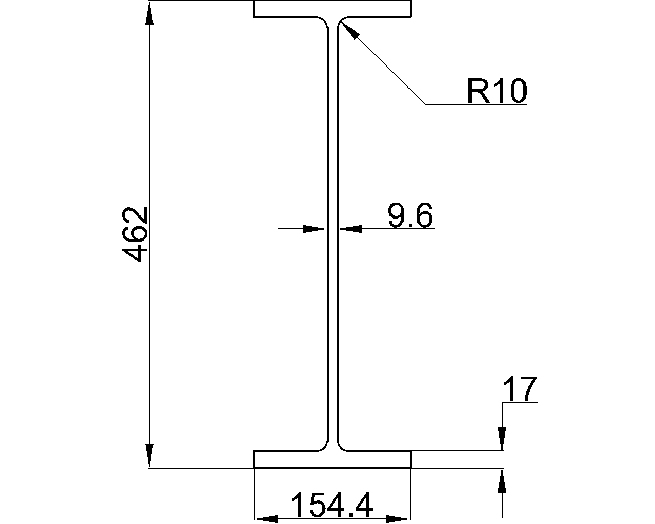
Dimension : 462×154.4×9.6×17
Depth : 462 mm
Width : 154.4 mm
Web Thickness : 9.6 mm
Flange Thickness : 17 mm
Root Fillet Radius : 10 mm
Sectional Area : 94.5 cm2
Unit Weight : 74.2 kg/m
How to read this UB reference
The designation identifies the beam series and its nominal size and mass classification. The source content separately reports the actual depth, width, web thickness, flange thickness, root fillet radius, sectional area, and unit weight. Keeping these items distinct helps prevent confusion between a section name and the dimensions used in drafting or design checks.
Dimensions and section properties
The listed depth and width describe the overall envelope of the section. Web and flange thicknesses help define the principal steel elements, while the root fillet radius describes the transition between them. The sectional area and unit weight support material takeoff, schedule preparation, and section-property review; they should not be treated as a substitute for a complete structural design verification.
Standard reference
The source identifies EN 10365:2017 as the referenced European standard for the dimensional and sectional-property information. When coordinating this entry with procurement documents, fabrication drawings, or a broader Universal Beams schedule, confirm that the project uses the same designation system and reference basis.
Using the DWG resource
The downloadable DWG can support CAD layout and steel detailing workflows. Before incorporating it into a production drawing, check the drawing units, scale, orientation, layer conventions, and project drafting requirements. Also compare the profile against the source data and the applicable supplier or project documentation.
Related steel-reference topics
For broader design and drafting work, pair this entry with references covering section properties, steel connections, Universal Beam terminology, and CAD/DWG detailing practices. These topics help connect profile identification with the checks and documentation required for a complete engineering workflow.
Frequently asked questions
What is the UB 457x152x74?
It is a Universal Beam reference designation. The page provides the corresponding source dimensions, section properties, standard reference, and a DWG download.
Which standard is referenced for this section?
The source content refers to EN 10365:2017. Use the project’s governing documentation to confirm that this reference is appropriate for procurement, fabrication, and design coordination.
Should the nominal designation replace the listed dimensions?
No. The designation helps identify the section, while the listed dimensions provide the dimensional reference needed for drawings and coordination. Use the source values shown on this page and verify them against project-controlled documentation when required.
Can the DWG be used directly for fabrication?
The DWG is a drafting reference, not a substitute for fabrication review. Confirm units, geometry, tolerances, drawing standards, and project-specific requirements before using it in a controlled fabrication document.
Are the listed section properties sufficient for structural design?
They are useful reference data, but a complete design also depends on the material specification, load effects, restraint conditions, connections, stability checks, and governing design requirements. A qualified engineer should complete the verification.