A sloped steel beam, rafter, brace, or stair-support member can have several valid lengths depending on how it is viewed and measured. The distance shown in plan is not necessarily the member’s true length, and the distance between work points may not equal the required cut length. Confusing these quantities can affect material takeoffs, connection geometry, shop dimensions, and CAD models.
The key is to distinguish the member’s spatial geometry from its fabrication limits. Designers and detailers should identify what each dimension represents, which reference points control it, and whether the member ends are square, beveled, coped, or extended into connections.
What Is the True Length of a Sloped Steel Member?
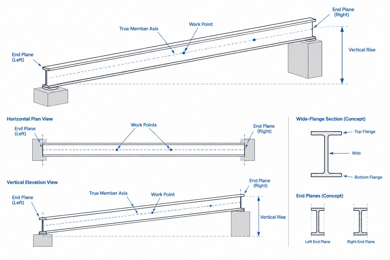
True length is the actual straight-line distance between two defined points along a member in three-dimensional space. For a simple member sloping in one vertical plane, it can be determined from the horizontal run and vertical rise:
True length = square root of (horizontal run squared + vertical rise squared)
If the member changes position in both plan directions while also changing elevation, all three coordinate differences must be considered. In that case, the true length is the three-dimensional distance between the controlling points.
This calculation is only meaningful when the endpoints are clearly defined. They might be grid intersections, member centerline work points, bearing points, column centerlines, connection work lines, or physical cut edges. Different endpoint definitions produce different lengths even when they refer to the same steel member.
Plan Length, Elevation Length, and True Length
A member can appear at different lengths in different drawing views because each view is a projection. Understanding those projections prevents a dimension taken from the wrong view from becoming a fabrication dimension.
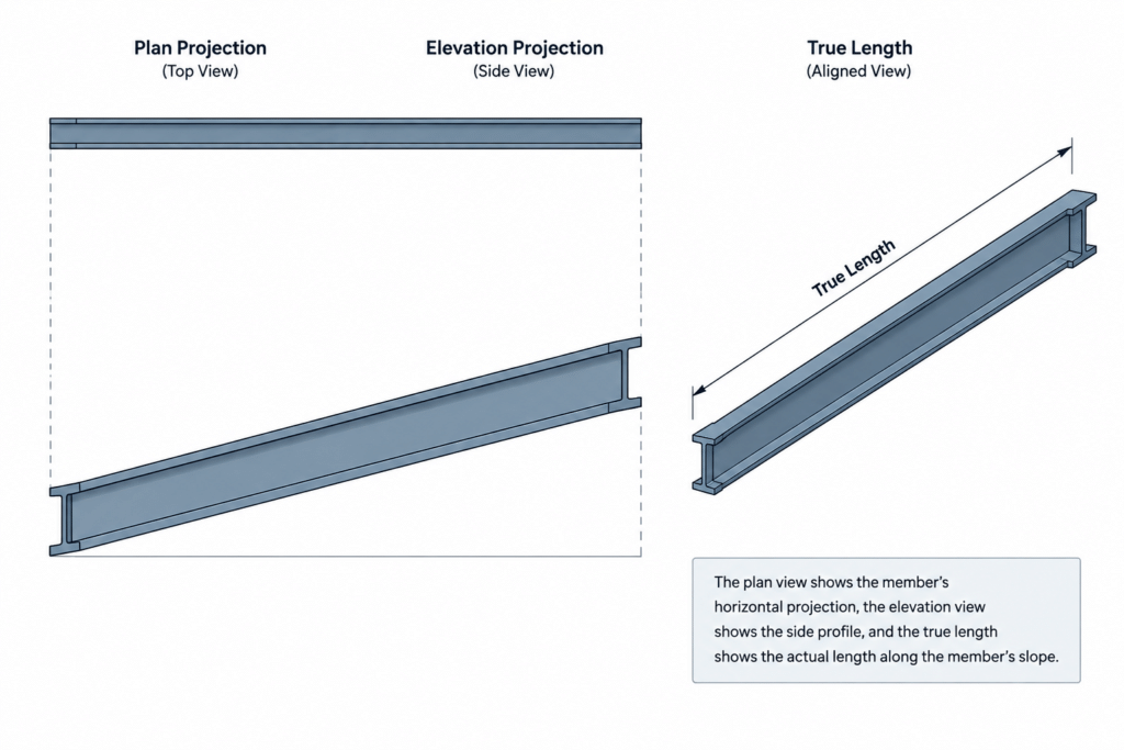
| Length term | What it represents | Typical use |
|---|---|---|
| Plan length | The member’s horizontal projection as seen from above | Grid coordination, floor layout, and horizontal positioning |
| Elevation projection | The member’s projected length in a vertical drawing plane | Slope coordination, elevations, and architectural clearances |
| True length | The actual spatial distance between defined endpoints | Member modeling, preliminary material length, and geometric checking |
| Work-point length | The true distance between designated connection or layout points | Structural geometry and connection development |
| Cut length | The fabricated length between physical end surfaces or extremities | Shop production and material processing |
For a beam sloping only in elevation, the plan projection is shorter than the true length. If the member is also skewed in plan, neither a plan view nor a conventional elevation may display its true length unless the view is aligned with the member.
Work-Point Length Is Not Automatically Cut Length
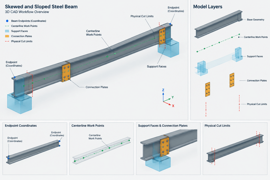
Structural framing is often laid out with work points and centerlines. A sloped beam may run from a work point at one column centerline to another work point at a different elevation. That work-point distance establishes the framing geometry, but it does not necessarily define where the steel ends.
The physical member may stop short of a work point to provide erection clearance. It may extend beyond a support centerline, bear on a seat, frame into a sloped end plate, or terminate against another member. Connection plates, end cuts, copes, and weld access can all change the final cut length.
A useful detailing sequence is:
- Establish the controlling work points and their coordinates.
- Confirm the member centerline or reference axis through those points.
- Locate the actual connection or bearing planes.
- Develop the physical end geometry at each plane.
- Dimension the cut length from the resulting end surfaces.
This sequence separates structural layout from fabrication geometry. It also makes later revisions easier to track.
How End Cuts Affect the Reported Length
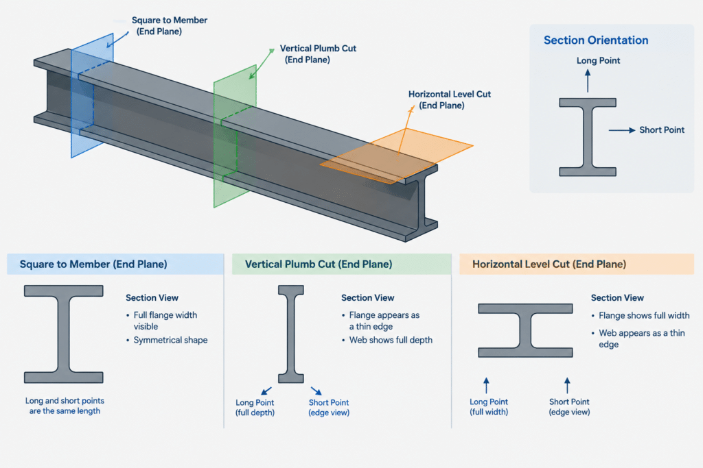
A square cut is perpendicular to the member’s longitudinal axis. A plumb cut is vertical. A level cut is horizontal. These cuts are not interchangeable on a sloped member, and each creates different flange and web edge positions.
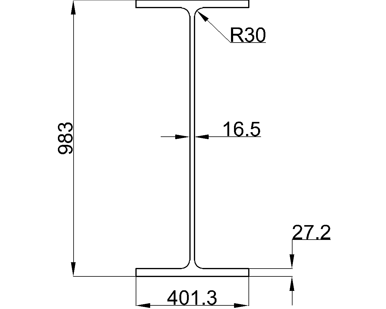
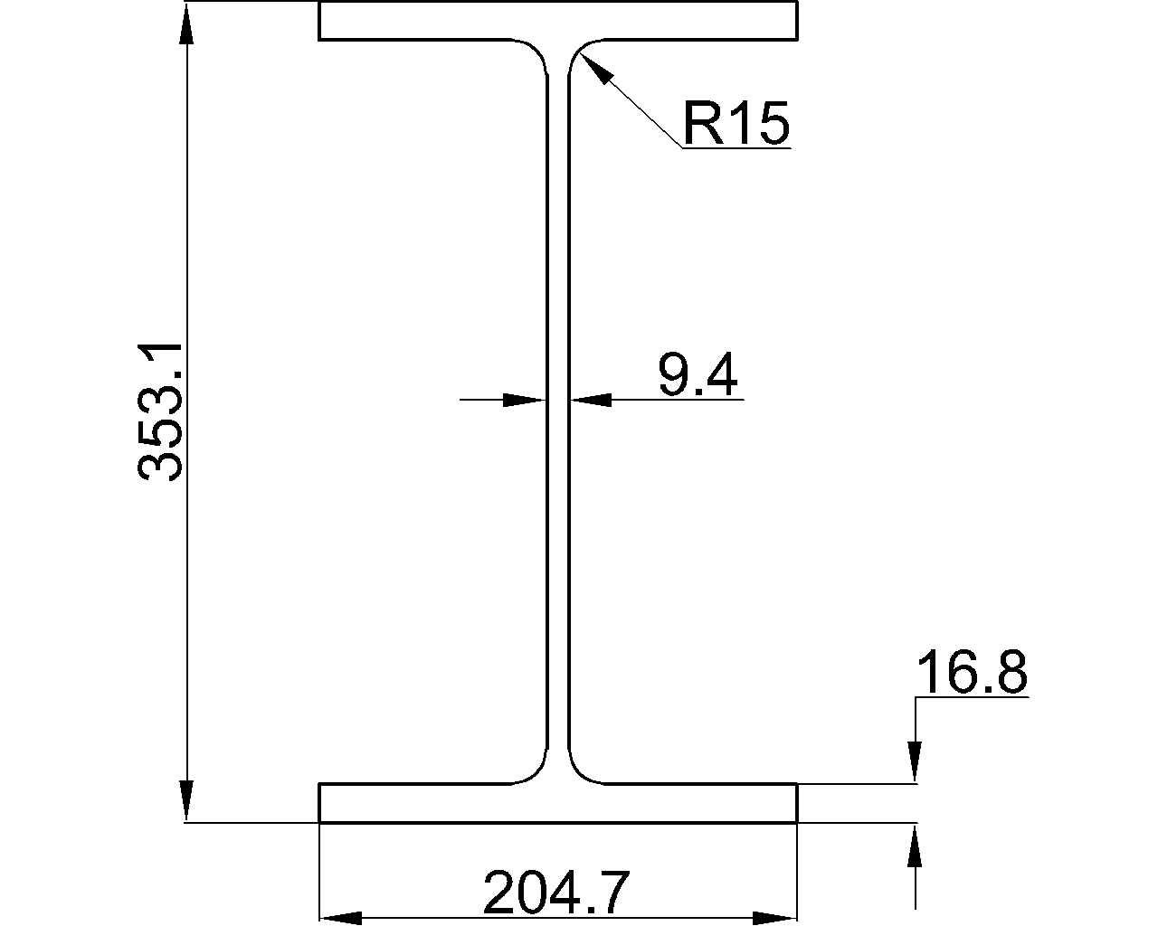
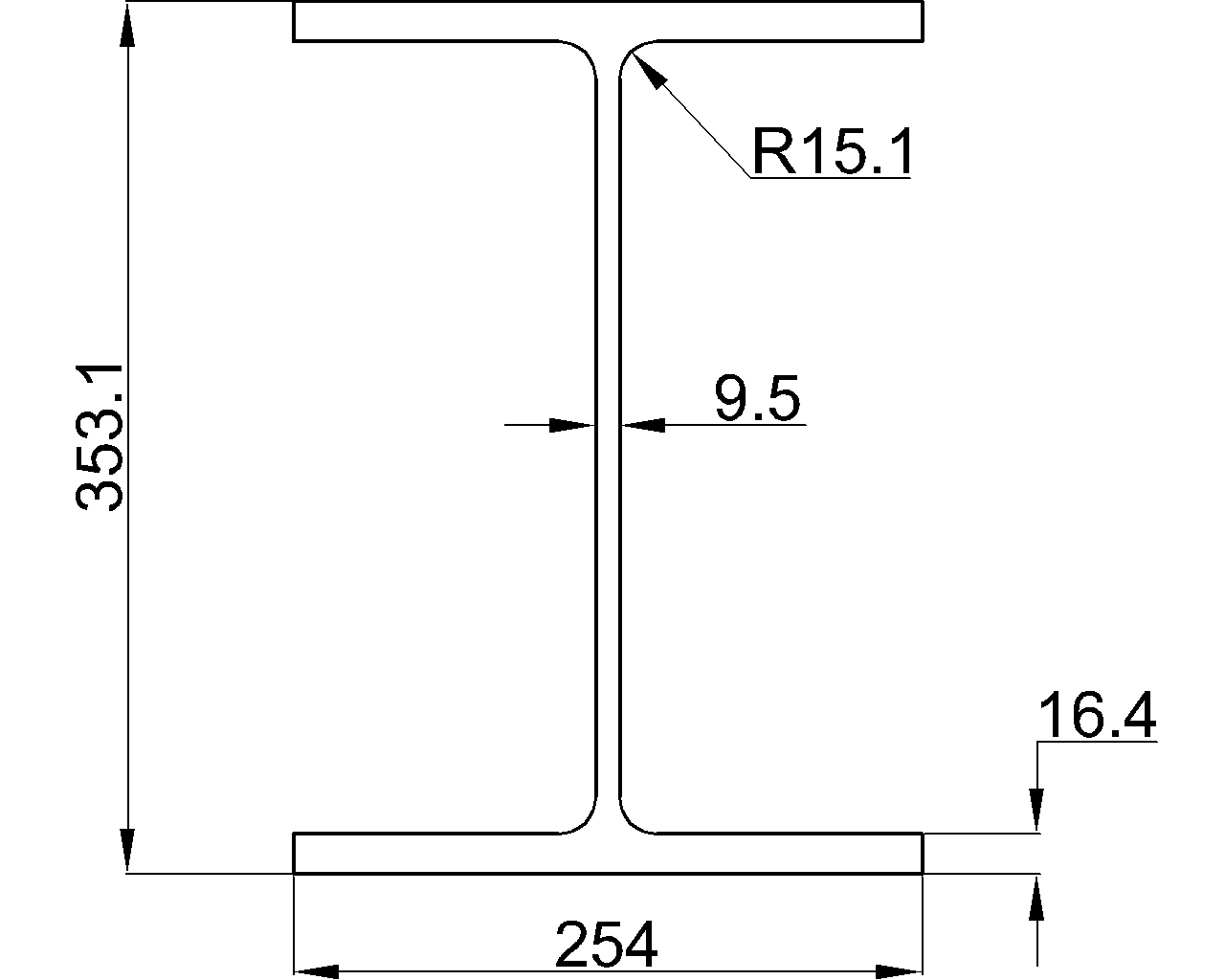
For example, a vertical end plane through a sloped wide-flange beam intersects the top flange, web, and bottom flange at different longitudinal locations. As a result, there may be no single physical endpoint that represents the entire section. A shop drawing may need to define the controlling edge, cut angle, long point, short point, or intersection with a reference line.
The same issue occurs with HSS and other closed sections. A mitered HSS end has different corner locations along the member axis. Simply labeling a centerline length does not completely describe the cut.
Connection planes need explicit definition
Connection geometry should identify whether a plate or supporting surface is vertical, horizontal, normal to the member, parallel to another member, or aligned to a grid. Terms such as “end plate” or “bearing plate” describe a component but do not, by themselves, establish its orientation.
In a coordinated model, the connection plane should be constrained independently from the beam axis. This helps prevent a software command from automatically making an end plane perpendicular to the member when the intended detail requires a plumb or skewed interface.
Centerline Length vs. Flange-Edge Length
The centerline of a straight prismatic member has one true length between two work points. Individual flange edges can have different end-to-end distances when the end cuts are not normal to the member axis. This distinction matters when dimensioning flange bevels, edge preparation, attached plates, and weld extents.
Do not infer a flange-edge dimension by copying the centerline length. Instead, project the actual end planes onto the modeled section. This is especially important for deep sections, sharply sloped members, and connections where small geometric changes can alter edge clearances.
Common CAD and Modeling Errors
Drawing only the plan projection
A line drawn between plan coordinates has no rise unless elevations are assigned. Its measured length is therefore a horizontal projection, not the true member length. A reliable model should locate both endpoints at their actual coordinates.
Using a rotated symbol instead of spatial geometry
Rotating a two-dimensional beam symbol can communicate direction on a plan, but it does not create a three-dimensional sloped member. Material lengths and connection cuts should not be extracted from that symbol without additional geometric verification.
Trimming the member before fixing work points
If a model is trimmed directly to connection plates before the structural work points are recorded, the original framing basis can become difficult to recover. Preserve reference lines, grids, or construction geometry so that cut lengths can be checked against the intended layout.
Measuring in an oblique view
A distance measured graphically from an unaligned elevation or perspective view may be a projection. Use coordinate-based measurements, an aligned view, or a three-dimensional distance tool that reports the actual endpoint separation.
Rounding intermediate geometry
Rounding the slope, rise, run, or angle before calculating endpoints can produce accumulated discrepancies. Maintain model precision during layout and apply drawing precision only to displayed dimensions, subject to the project’s detailing requirements.
A Practical Verification Workflow
Before releasing a sloped member for fabrication or using its length in a takeoff, check the geometry in a consistent order:
- Confirm the references: Identify grids, centerlines, work points, support faces, and controlling elevations.
- Check all coordinates: Verify horizontal position and elevation at both ends. For skewed framing, check both plan directions.
- Verify orientation: Confirm which face is up and whether the web is vertical, tilted, or rotated about the member axis.
- Measure work-point distance: Use the actual spatial coordinates rather than a projected view.
- Define connection planes: Establish their orientation and offsets from work points.
- Develop end cuts: Intersect the section with the intended planes and include copes or other end preparations.
- Compare reported lengths: Distinguish centerline, work-point, overall, long-point, short-point, and cut dimensions.
- Cross-check views: Make sure plans, elevations, sections, schedules, and model information describe the same geometry.
What Should Be Shown on Drawings?
The necessary information depends on the project and drawing type, but a sloped member generally needs an unambiguous combination of location, elevation, slope, orientation, and end geometry. Useful information may include endpoint elevations, work-point dimensions, grid references, slope direction, connection-plane orientation, and enlarged end details.
Avoid over-dimensioning the same geometry in several different ways unless the dimensions are clearly identified as reference information. Redundant rise, run, angle, true-length, and endpoint dimensions can conflict after a revision. Select a controlling dimensional scheme and use secondary information for checking rather than independent control.
Final Detailing Principle
There is no universally correct “beam length” without a stated reference. A plan length describes a projection, a work-point length describes structural layout, and a cut length describes fabricated steel. For sloped and skewed members, those values should be developed and labeled separately.
When the work points, member axis, connection planes, and physical end cuts are all defined, the geometry becomes traceable. That traceability is more valuable than a dimension taken from an isolated view because it allows designers, detailers, fabricators, and erectors to understand exactly what the reported length controls.