A top of steel elevation identifies the vertical position of a structural steel surface, usually the top flange of a beam or girder. It is a simple reference in appearance, but interpreting it correctly requires attention to member orientation, actual section depth, floor geometry, camber, and the drawing conventions established for the project.
Top of steel is commonly abbreviated as TOS, although abbreviations can vary among engineering, architectural, and fabrication documents. A drafter or detailer should confirm the project legend and general notes rather than assume that every elevation tag refers to the same surface or condition.
What Does Top of Steel Mean?
For a level, upright W-shape beam, top of steel normally means the uppermost surface of the top flange at the referenced location. The elevation is measured from the project datum used by the design documents. That datum may be tied to a building level, survey reference, or another defined vertical control point.
A TOS elevation does not, by itself, describe the finished floor elevation. Floor systems often include deck, slab, grout, plates, or other materials above the steel. The difference between finished floor and top of steel depends on the assembly shown in the project documents.
Likewise, TOS should not automatically be interpreted as the beam centerline elevation. The vertical centerline of an upright rolled shape is below the top flange by approximately half the actual member depth when the section is symmetric. Connection geometry, detailing references, and modeling practices may use either surface elevations or member centerlines, so the selected reference must remain clear.
TOS, BOS, and Member Centerline
Several vertical references may be used for the same member:
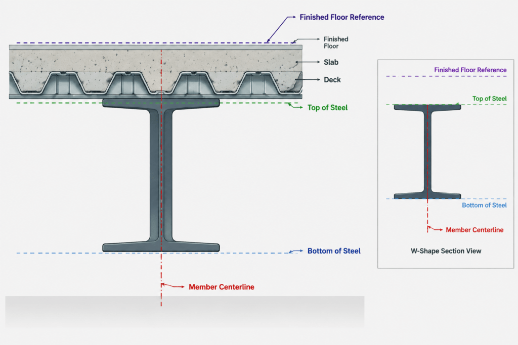
- Top of steel (TOS): the elevation of the upper steel surface at the indicated point.
- Bottom of steel (BOS): the elevation of the lowest steel surface, often used to check clearance below framing.
- Member centerline: a modeling or layout reference passing through the section at its defined insertion or geometric center.
- Top of finished floor: an architectural elevation that may include material above the supporting steel.
- Top of deck or slab: a surface reference that must not be confused with the supporting beam flange.
For a level member in its standard upright orientation, the relationship between top and bottom steel is governed by the actual section depth. In symbolic form:
BOS elevation = TOS elevation − actual member depth
This relationship should use verified section data, not the nominal depth embedded in a shape designation. A W-shape name identifies a nominal family and weight category; it is not a substitute for the published actual depth of the selected section.
Why Actual Shape Depth Matters
Members with similar nominal designations can have different actual depths. If a CAD model or detail is created by treating the nominal designation as an exact geometric dimension, bottom-of-steel clearances and connection locations may be wrong.
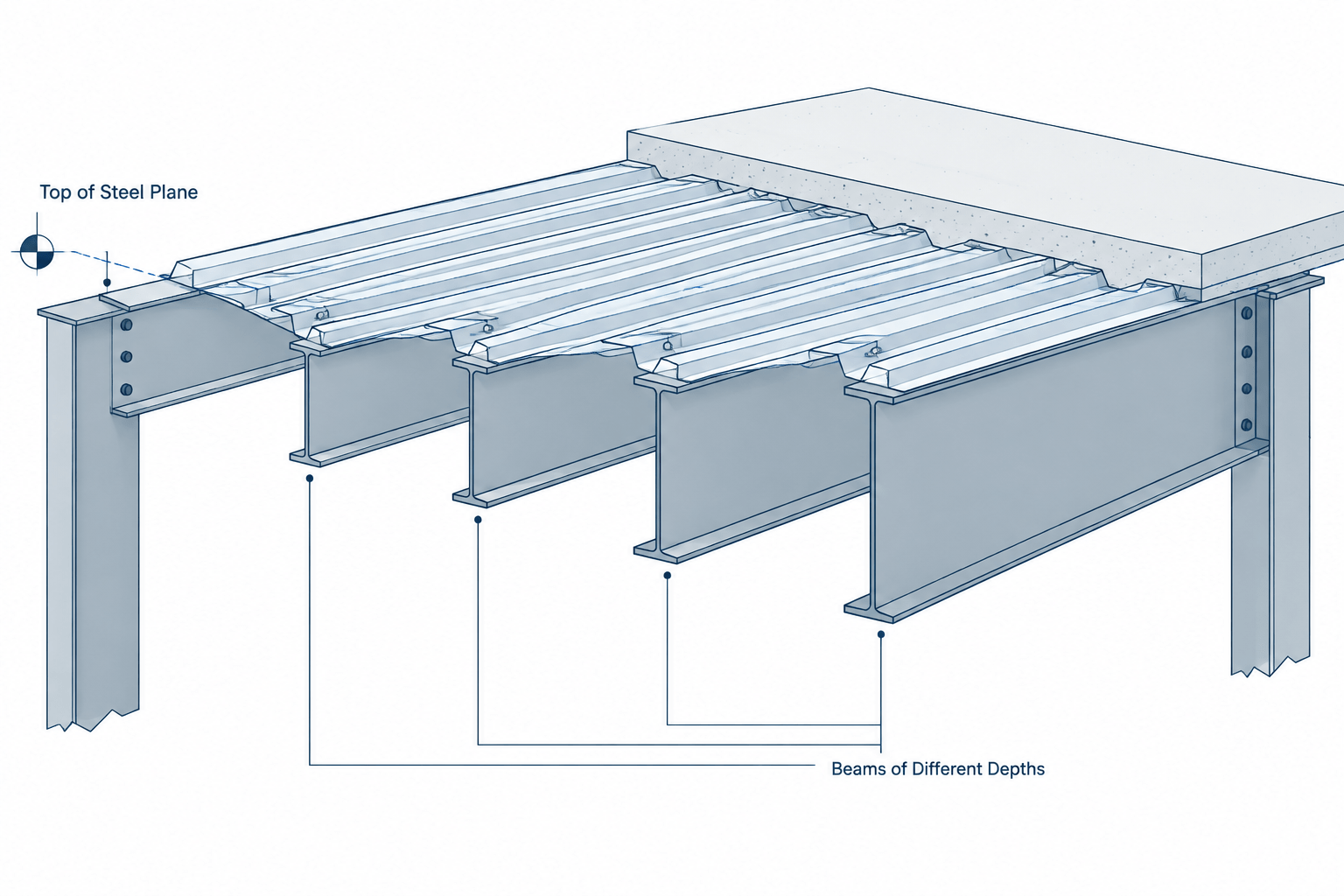
This distinction is especially important when several beam sizes frame into a common girder or support a common floor plane. Their top flanges may share one elevation while their bottom flanges occur at different elevations. Aligning members by centerline instead of by top flange can unintentionally create steps in the supporting surface.
A reliable workflow begins with the required top surface, then places each member using verified section geometry. The model should derive the lower surface from the actual depth rather than from a rounded family name.
Level Members, Sloped Members, and Point-Specific Elevations
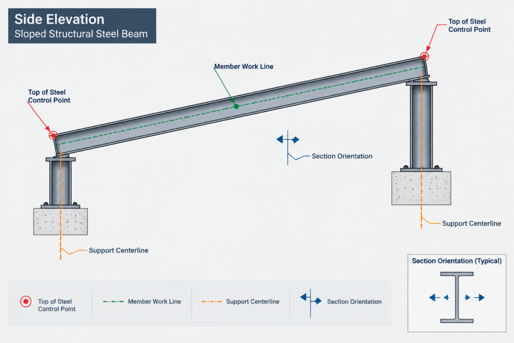
A single TOS elevation can define an entire straight member only when its top surface is intended to remain level. A sloped beam requires additional information, such as elevations at both ends, a stated slope, or geometry controlled by established work points.
For sloped framing, the phrase “top of steel elevation” is incomplete unless the location is also known. The elevation at the left end, right end, support centerline, column face, and beam work point may differ. Details should identify where an elevation applies and should avoid mixing work-point elevations with cut-end or bearing-point elevations.
Section orientation also matters. A sloping W-shape may be modeled with its web vertical, with its cross section perpendicular to the member path, or according to another project-specific rule. These choices affect the precise position of flange edges and connection material. The intended modeling convention should be confirmed before connection details are developed.
Camber and the Meaning of the Elevation
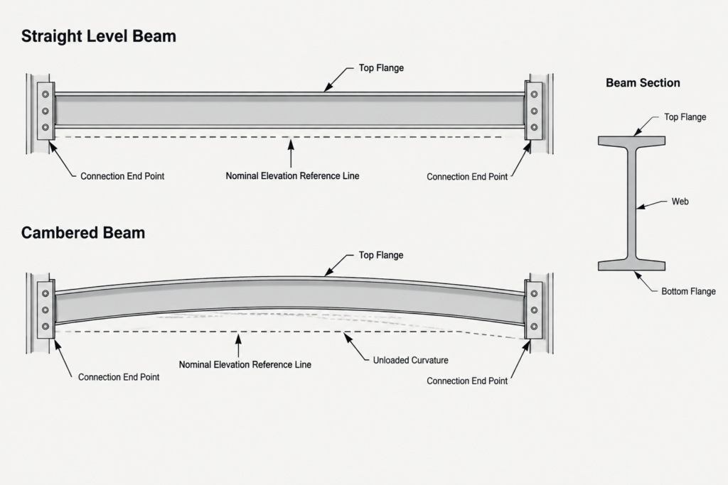
Camber introduces another distinction: the documented design elevation, the fabricated unloaded shape, and the in-service position are not necessarily identical. A cambered beam has intentional upward curvature before the anticipated loading sequence is complete.
A framing plan may show a nominal top-of-steel line while separately indicating camber requirements. That does not necessarily mean every point along the unloaded beam’s top flange lies on the nominal line. The center region of the member may be above a straight line connecting its ends.
Drafters should avoid treating camber as an arbitrary vertical translation of the complete member. Camber is curvature, not a uniform offset. Its representation also depends on the purpose of the drawing:
- A design plan may indicate the required camber without drawing the curvature to scale.
- A fabrication detail may show the member in its shop orientation and identify the cambered direction.
- An erection model may use simplified geometry while preserving camber as member data.
- A coordination model may need an agreed convention for clearance checks.
The project engineer and fabricator should resolve how camber affects elevations, attachments, deck support, and field fit. A generic CAD block cannot establish those project-specific conditions.
Common Framing Conditions
| Condition | Primary vertical reference | Detailing concern |
|---|---|---|
| Level floor beam | Common TOS plane | Use actual section depth to determine BOS and connection geometry. |
| Beam framing into a deeper girder | Beam TOS and girder TOS or connection work point | Do not assume centerlines align vertically. |
| Roof beam on a slope | TOS at defined points or a controlled slope | State where each elevation applies and confirm section orientation. |
| Cambered girder | Design reference line plus camber information | Distinguish nominal elevations from unloaded fabricated curvature. |
| Beam beneath a depressed area | Local TOS elevation | Coordinate steps with deck, slab, and adjacent framing. |
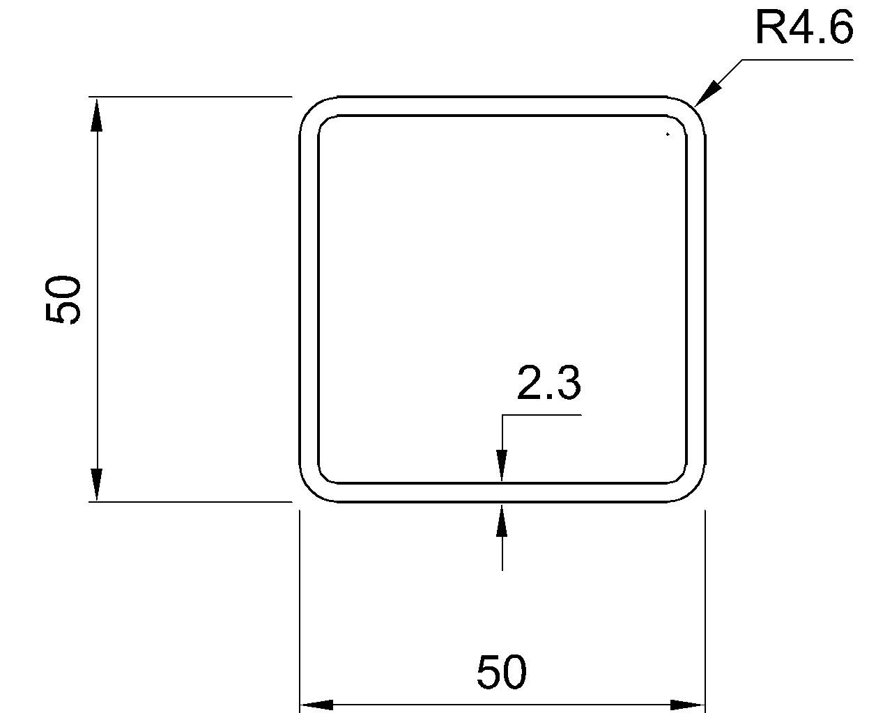
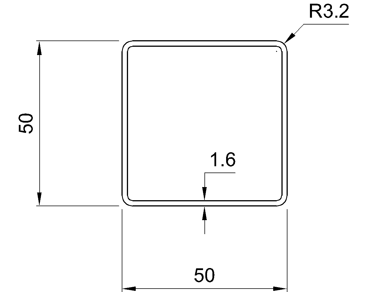
| HSS header or support | Specified outside face | Confirm whether the elevation refers to the top wall, centerline, or attached plate. |
Connection Detailing at a Controlled TOS
When beams of different depths share a common top-of-steel elevation, their webs and bottom flanges occupy different vertical positions. This affects shear connection placement, bolt access, cope geometry, stiffeners, and the relationship to the supporting member.
A connection should be developed from the established member geometry rather than centered by appearance. For example, placing a connection at the geometric middle of each incoming beam may conflict with a consistent connection zone on the support. Conversely, forcing all connections to a common vertical location may require different edge clearances or cope conditions for different beam sizes.
Top flange alignment also affects deck bearing and slab edges. Plates, seats, angles, and other connection elements should be checked against both the framing elevation and the actual rolled-shape geometry. Rolled fillets and flange slopes or contours may create local clearance issues even when the overall TOS is correct.
A Practical CAD and Modeling Workflow
- Confirm the datum. Identify the vertical reference used by the structural drawings and coordinate it with architectural and civil information.
- Identify the controlled surface. Determine whether the stated elevation applies to top of flange, top of plate, member centerline, deck, slab, or another surface.
- Locate the control point. For sloped framing, establish whether the elevation is given at a grid line, support centerline, face of support, work point, or member end.
- Select verified shape geometry. Use the actual depth, flange width, and thickness information associated with the specified section.
- Set the insertion convention. Decide whether CAD objects are inserted by centerline, top center, centroid, or another consistent point.
- Check adjacent construction. Review deck, slab, bearing plates, edge angles, openings, and clearance zones.
- Review special conditions. Account for slope, camber, member rotation, skew, and elevation changes.
- Label clearly. Place elevation tags where their application is unambiguous and avoid relying solely on object properties that may not appear in plotted documents.
Quality-Control Checks Before Issuing Drawings
- Verify that members supporting one floor plane are aligned by the intended surface rather than unintentionally by centerline.
- Compare bottom-of-steel elevations with required architectural and mechanical clearances.
- Check that sloped-member elevations are tied to defined locations.
- Confirm that section depth comes from verified shape data.
- Review whether plates or seats change the effective supporting elevation.
- Make sure camber direction and representation are consistent across plans, details, and models.
- Check that elevation abbreviations match the project legend.
- Coordinate revised member sizes because a substitution can change BOS even when TOS remains fixed.
Use Elevations as Geometric Controls, Not Isolated Labels
A top of steel elevation is most useful when treated as part of a complete geometric system. It works together with the project datum, verified shape dimensions, member orientation, work points, slopes, and connection details. Reading the elevation tag without those relationships can produce a model that appears aligned in plan but fails in section.
For CAD and detailing work, establish the controlled surface first, use actual section geometry, and document where each elevation applies. That approach makes framing plans easier to interpret and reduces avoidable conflicts among steel, deck, floor assemblies, connections, and building services.