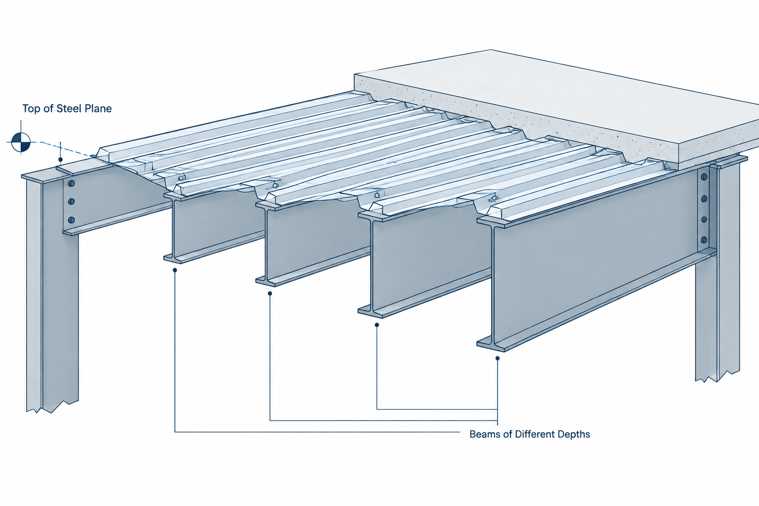
Tag: steel CAD
-
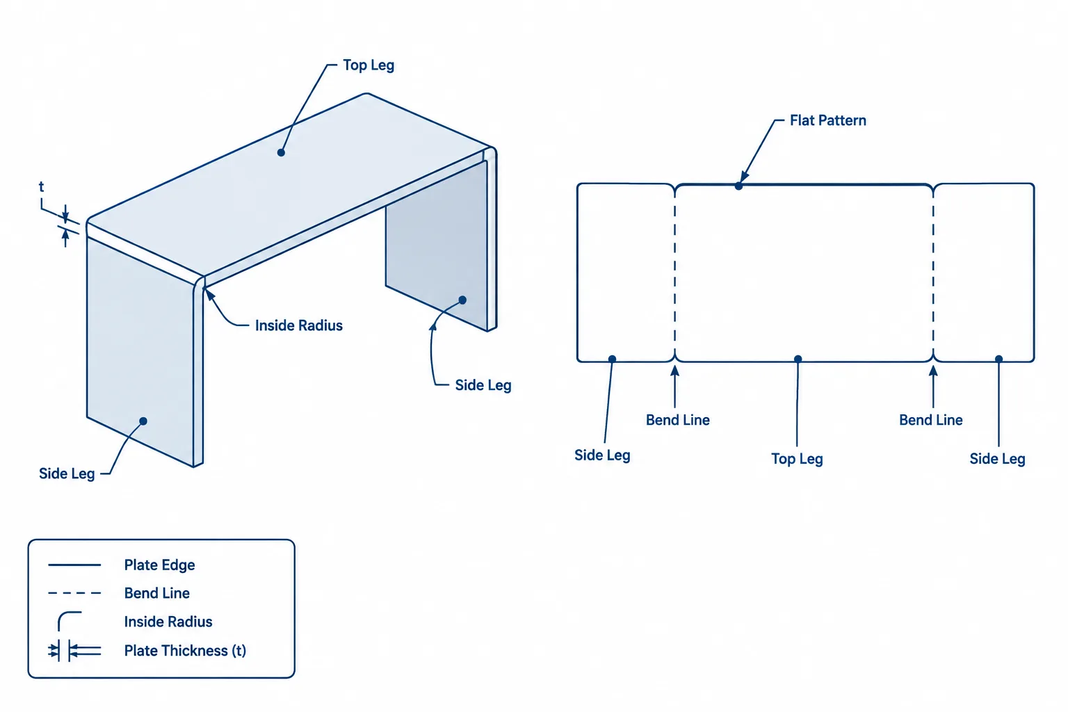
Bent Structural Steel Plates: Flat Length, Bend Lines, and CAD Detailing
Learn how to detail structural steel bent plates, including inside and outside dimensions, bend lines, flat length, bend allowance, orientation, and CAD checks.
Written by
-
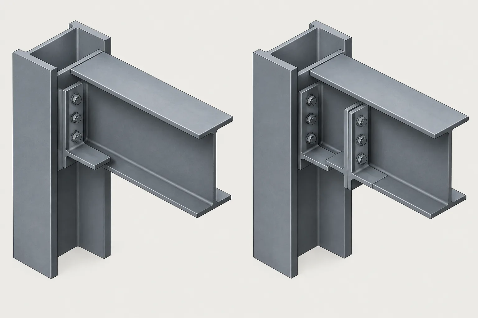
Single-Angle vs. Double-Angle Shear Connections: A Steel Detailing Comparison
Compare single-angle and double-angle shear connections, including orientation, framing geometry, bolts, welds, clearances, drawing views, and CAD checks.
Written by
-
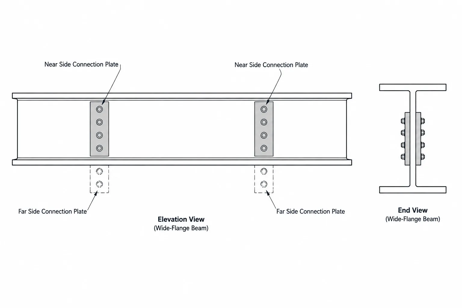
Near-Side vs. Far-Side Steel Detailing: Reading Plates, Holes, and Bolts in Elevation
Learn how near-side and far-side steel components are shown in elevations, sections, and CAD details without mirroring connection geometry.
Written by
-
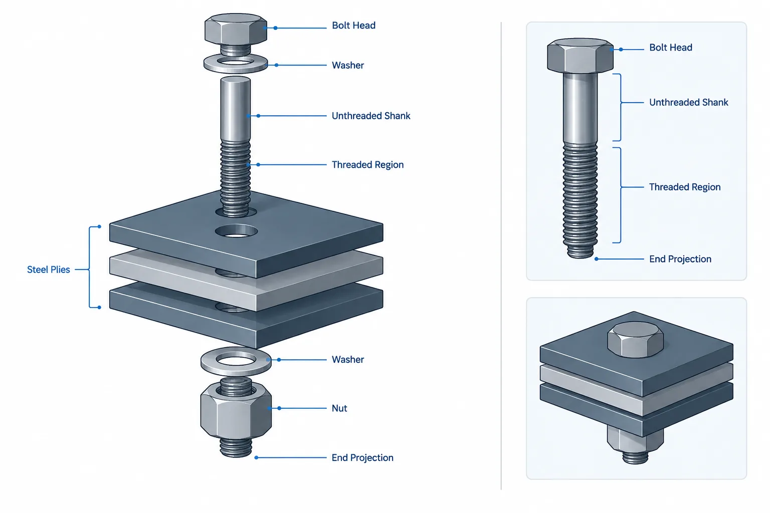
Structural Bolt Grip Length, Ply Thickness, and Thread Location: A Detailing Guide
Learn how ply thickness, washers, thread location, bolt length, and connection geometry affect structural bolt detailing and coordination.
Written by
-
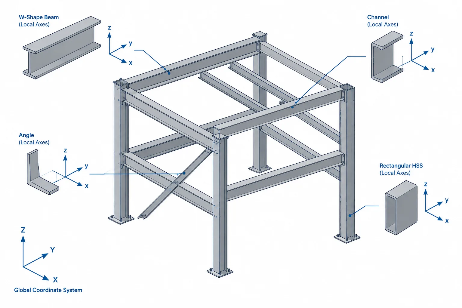
Local Axes in Structural Steel CAD Models: Member Direction, Section Rotation, and Coordination
Learn how structural steel local axes control member direction, section rotation, offsets, connection orientation, and reliable CAD model coordination.
Written by
-
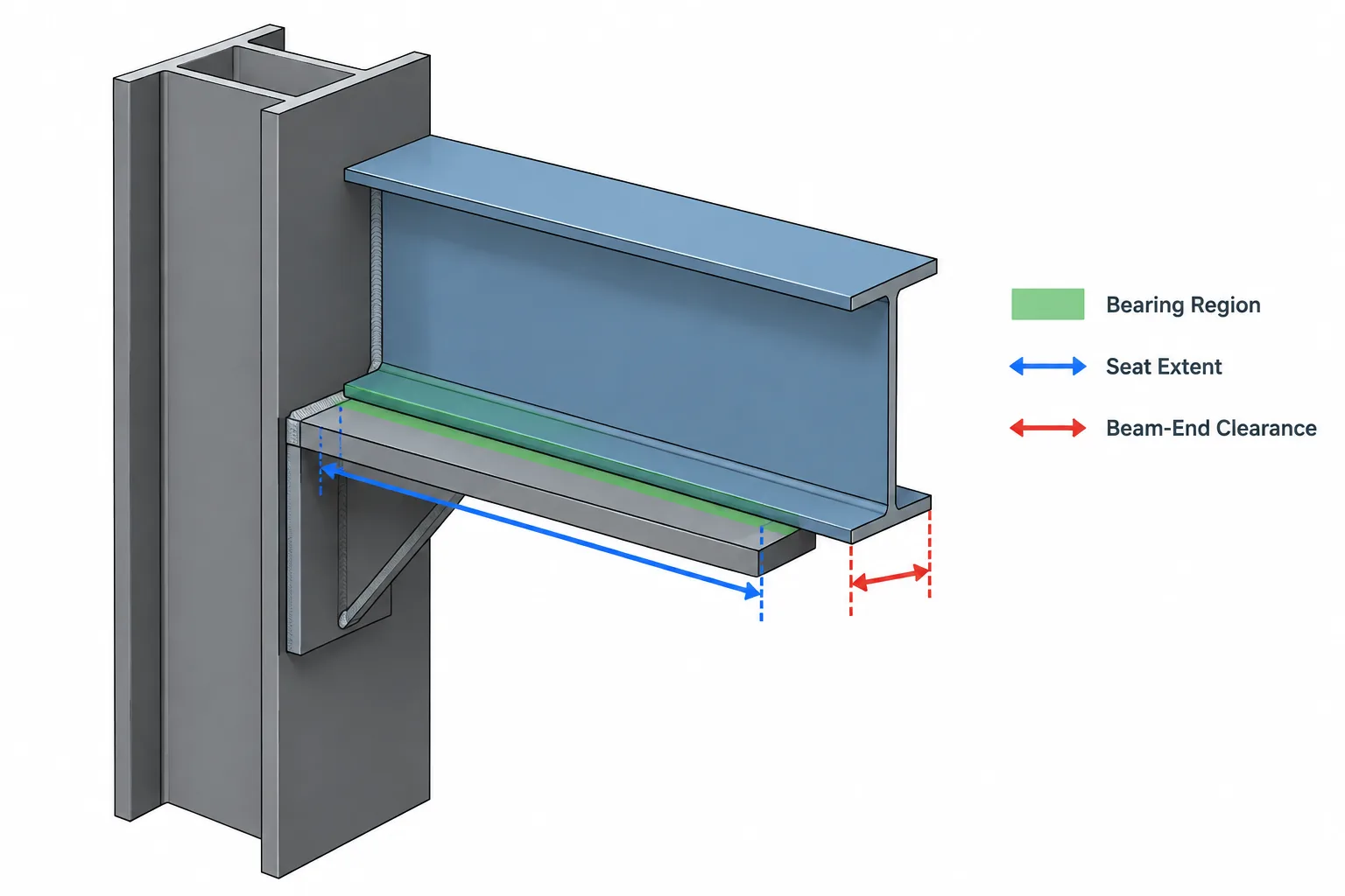
Steel Beam Bearing Length, Seat Length, and End Clearance: A Detailing Guide
Learn how steel beam bearing length differs from seat length and end clearance, and how to coordinate these dimensions in structural drawings and CAD models.
Written by
-
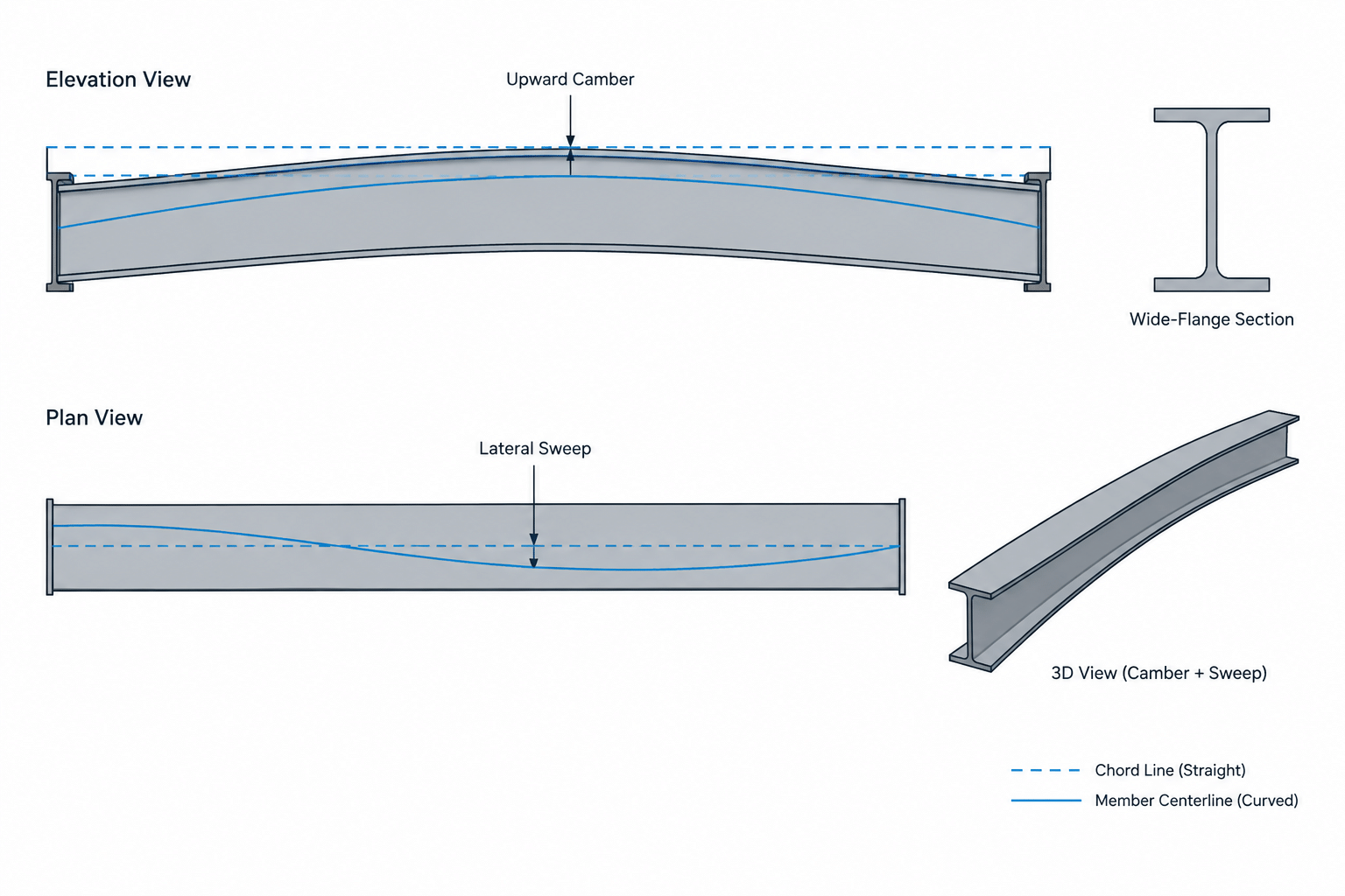
Camber vs. Sweep in Structural Steel Members: Geometry, Measurement, and Detailing
Learn how camber, sweep, slope, and out-of-straightness differ in structural steel, including measurement references and practical CAD detailing guidance.
Written by
-
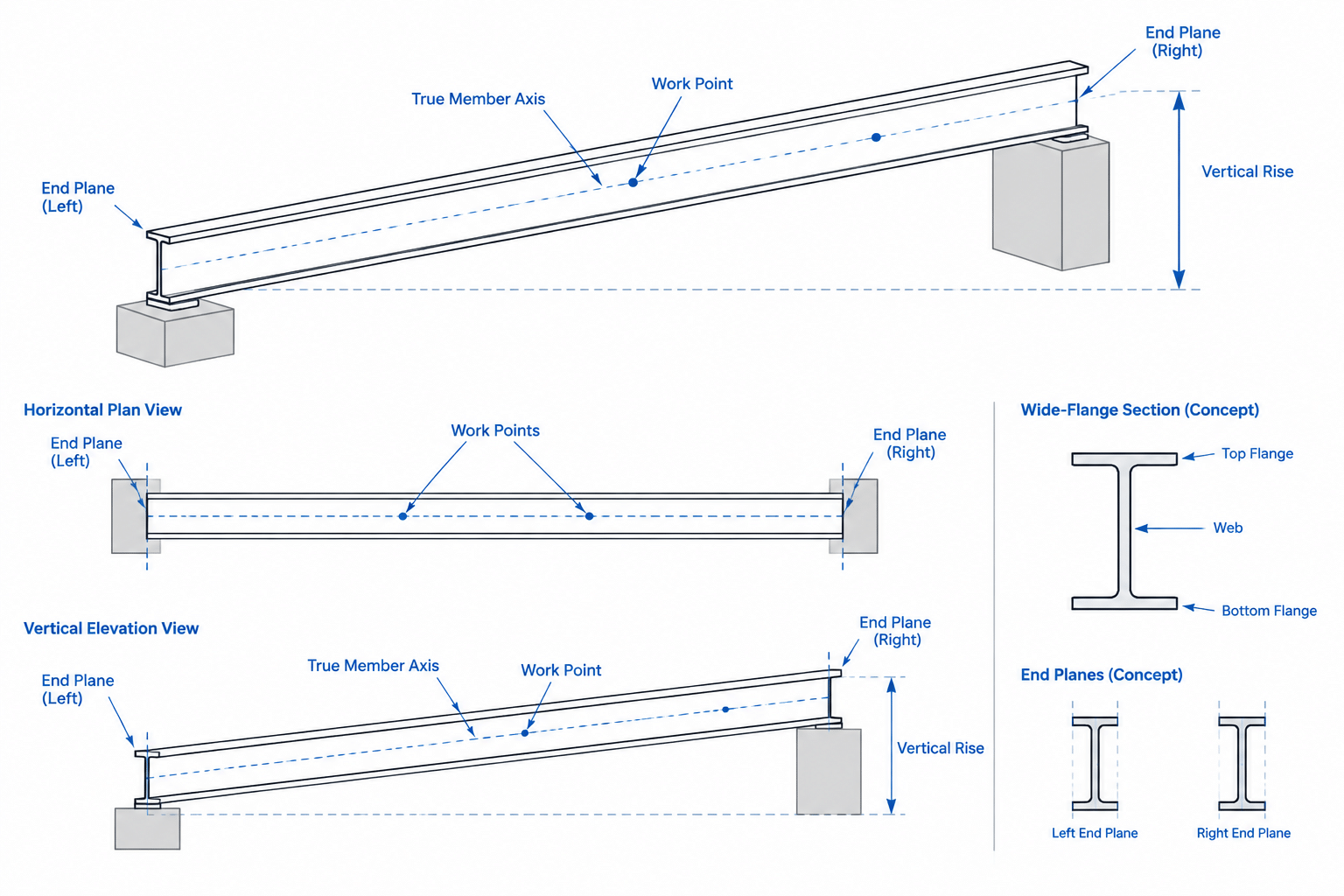
True Length vs. Plan Length for Sloped Steel Members: A Detailing and CAD Guide
Learn how true length, plan length, slope, end geometry, and connection planes affect sloped steel beam detailing, fabrication dimensions, and CAD models.
Written by
-
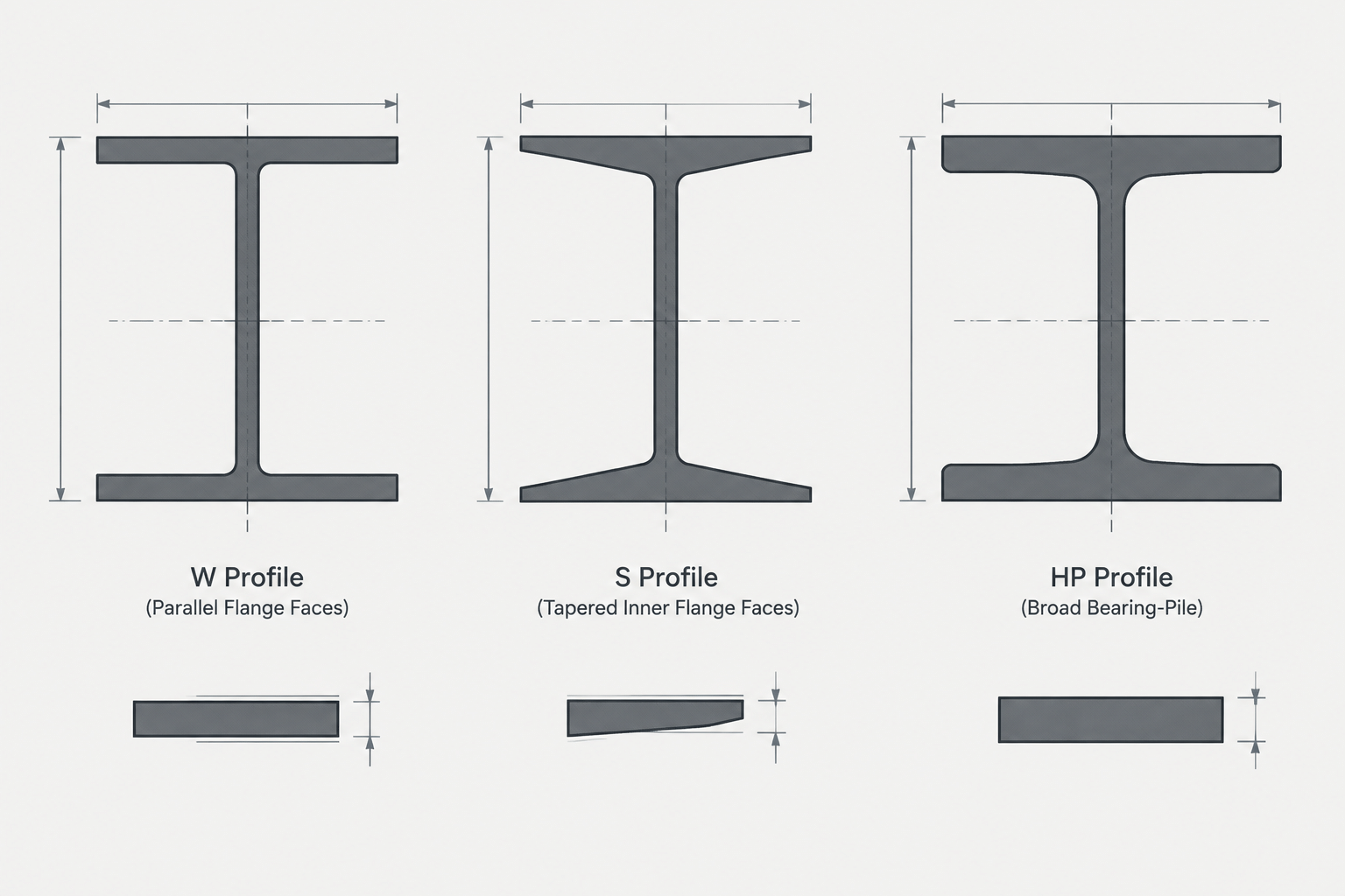
W-Shape vs. S-Shape vs. HP Shape: How to Identify and Detail Steel I-Sections
Compare W, S, and HP steel shapes by flange geometry, proportions, designations, typical uses, and practical CAD and detailing considerations.
Written by
-
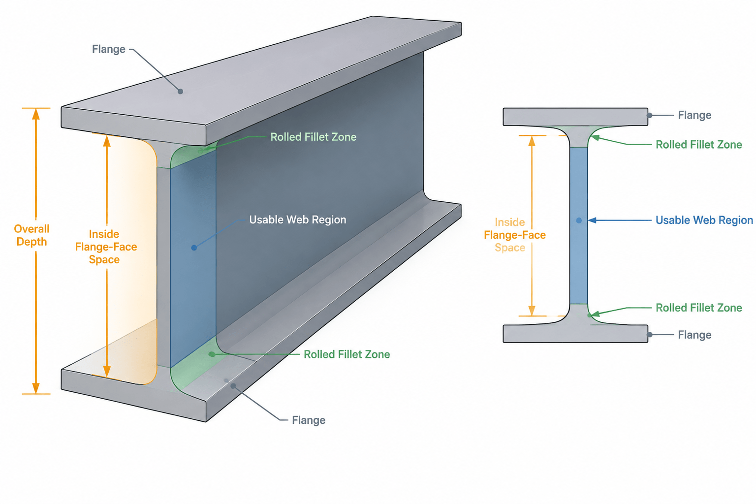
Clear Web Depth in W-Shapes: Flange Faces, Fillets, and Connection Fit
Learn how clear web depth differs from overall W-shape depth, why rolled fillets reduce usable space, and how to check plates, bolts, welds, and CAD details.
Written by
-
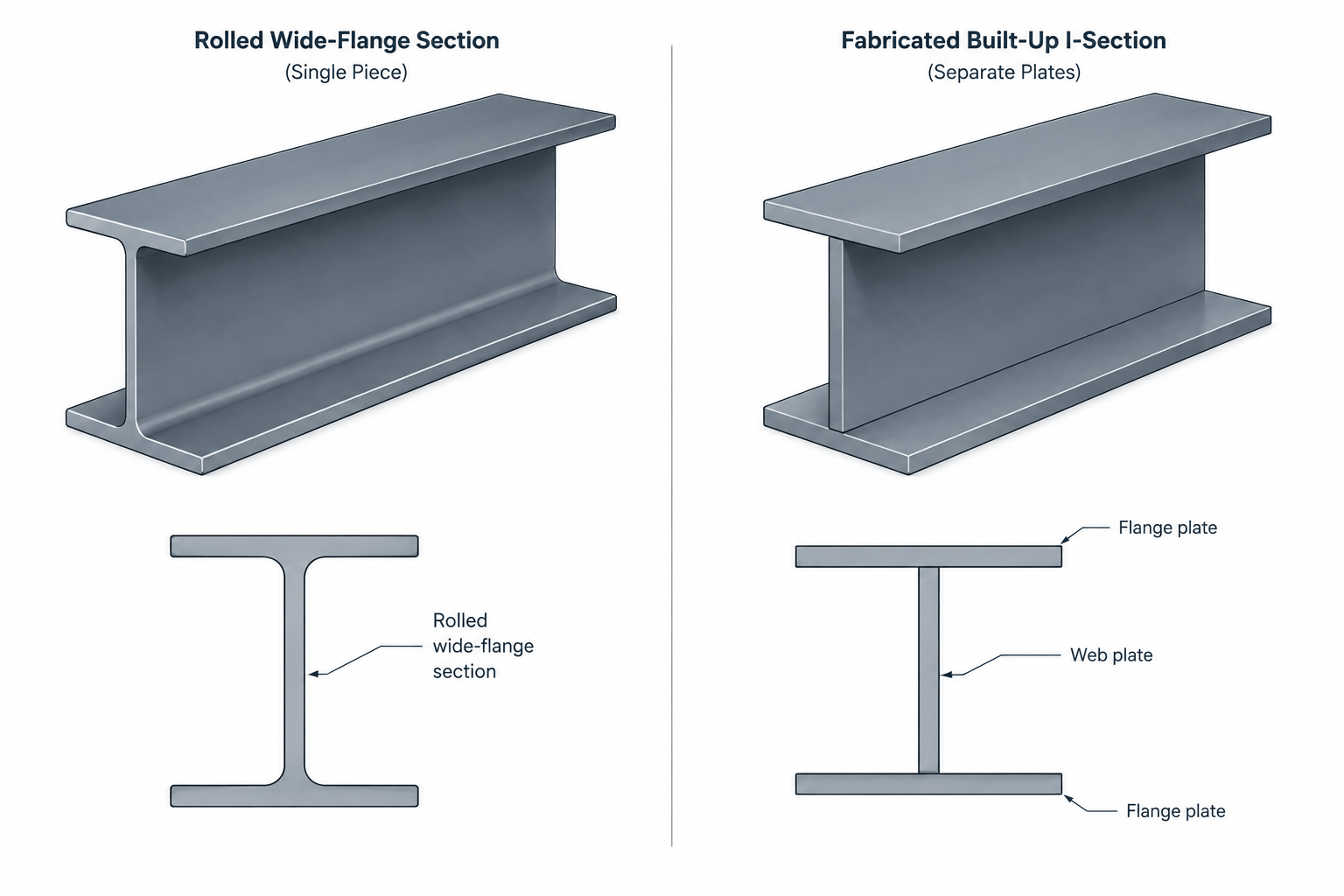
Rolled Shapes vs. Built-Up Steel Members: How to Read, Model, and Detail the Difference
Learn how rolled shapes differ from built-up steel members, how each appears on structural drawings, and what drafters should verify before modeling or fabrication.
Written by
-
Top of Steel Elevations in Structural Drawings: TOS, BOS, Slopes, and Camber
Learn how top of steel elevations relate to beam depth, slope, camber, connections, and CAD coordination in structural steel drawings.
Written by