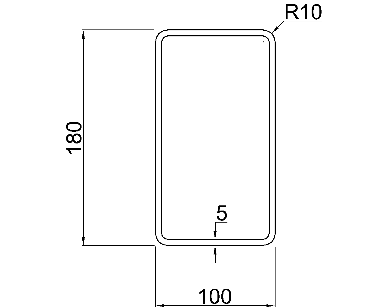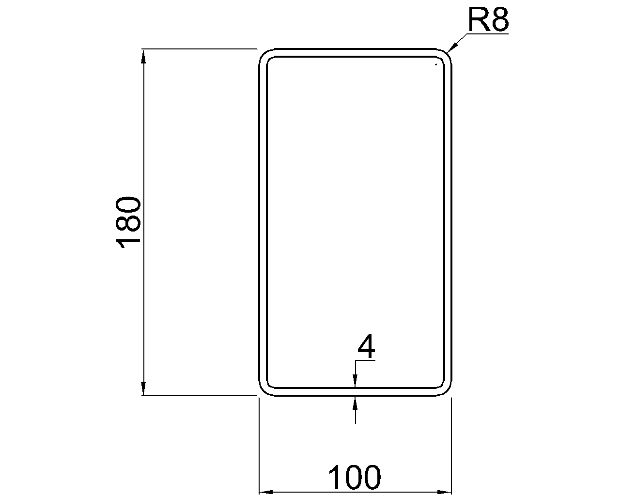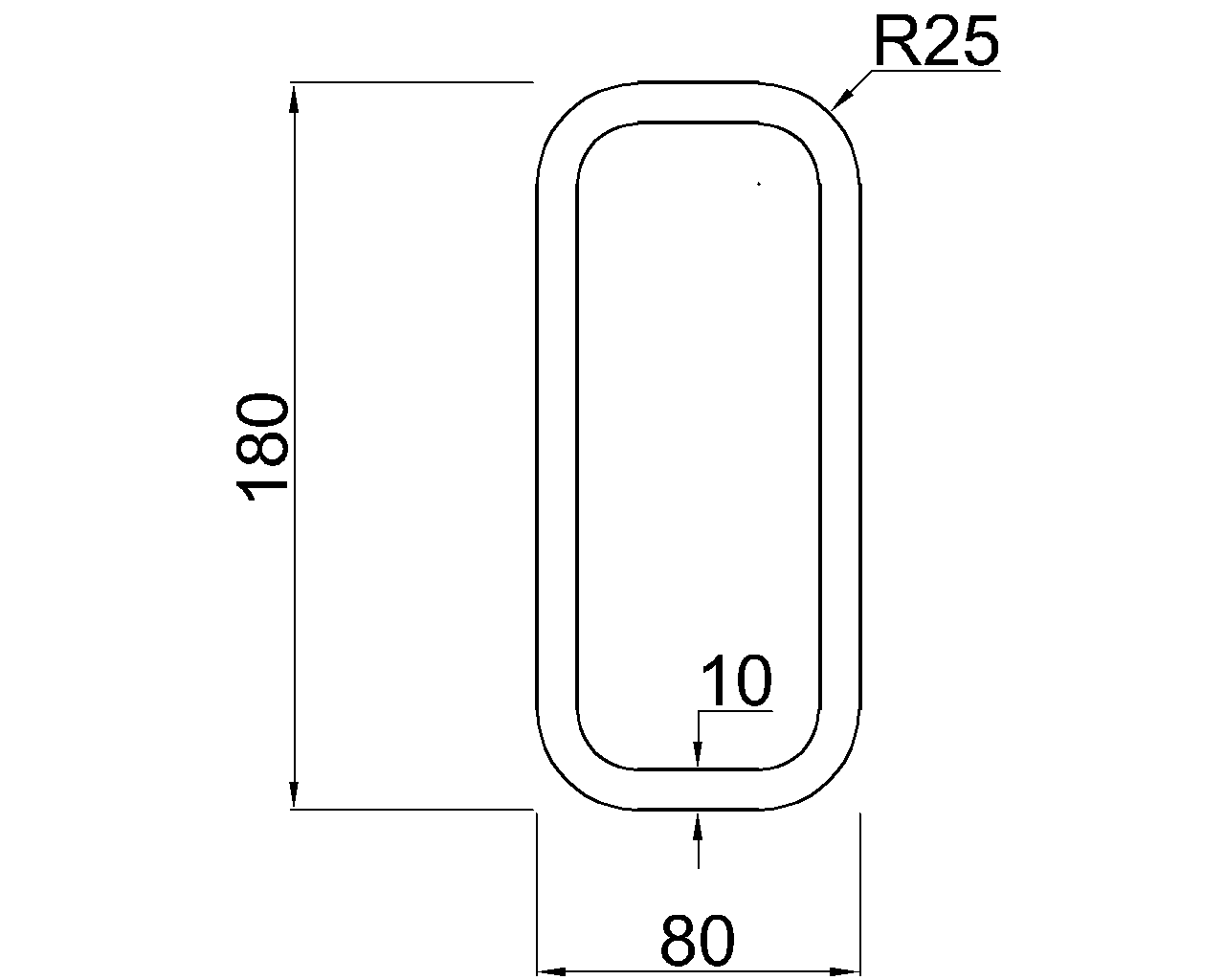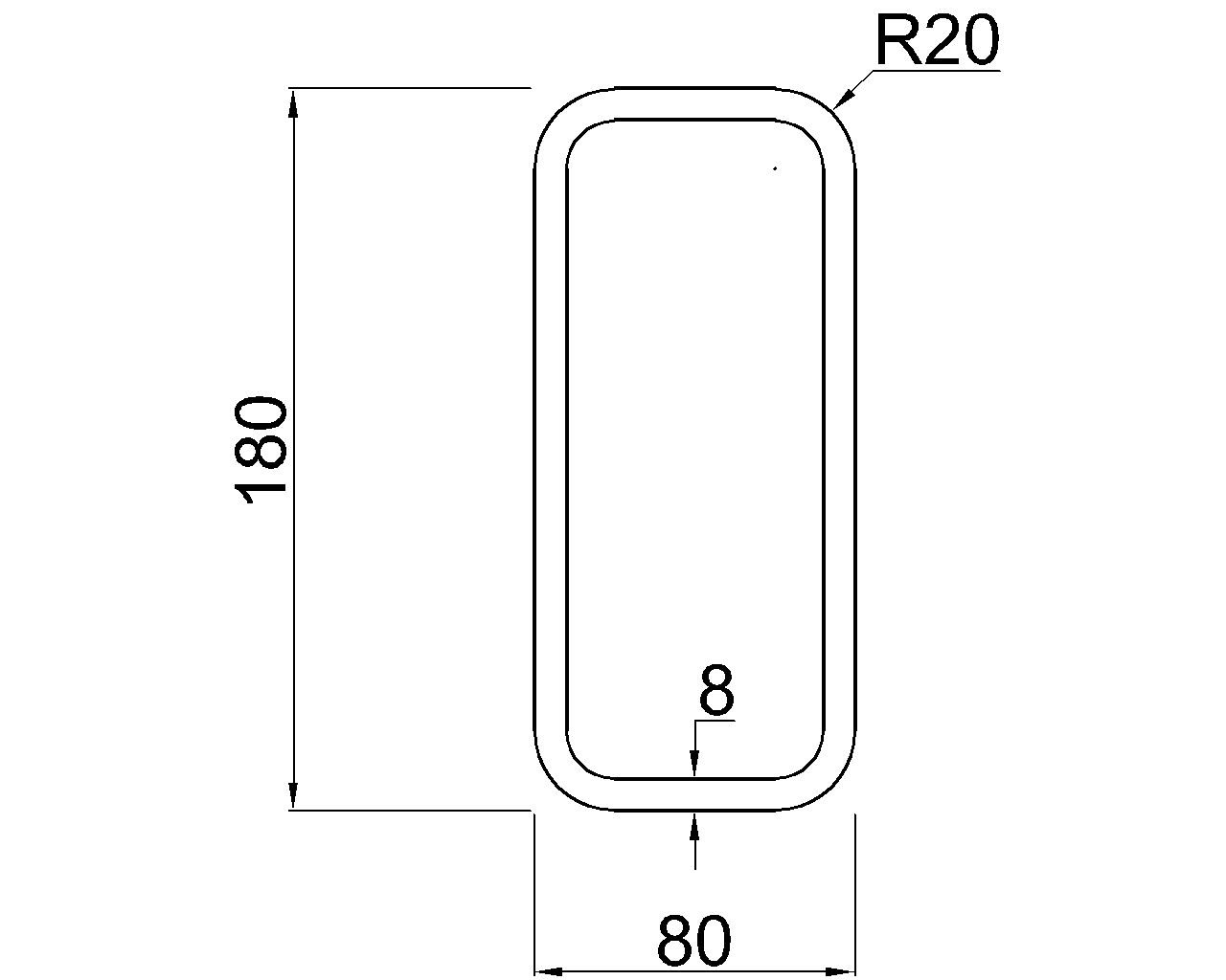
Structural tee WT shapes are common in trusses, bracing systems, framing connections, equipment supports, and other applications where an open section with one flange and one stem is useful. Although a WT resembles a simple letter T, its geometry requires more care than a schematic centerline suggests. The centroid is not at the midpoint of the overall depth, the flange-to-stem intersection includes rolled fillets, and one edge is typically created when a larger rolled shape is split.
For designers and drafters, the important distinction is between the nominal identity of the shape, the published section properties, and the physical geometry needed for fabrication. A reliable workflow uses each type of information for its intended purpose rather than trying to derive the entire tee from its designation.
What Is a WT Structural Tee?
A WT is a structural tee associated with the wide-flange shape family. It is commonly produced by splitting a W-shape longitudinally through its web. The remaining portion has a flange across the top and a stem projecting from it. Depending on its orientation in a drawing, the flange may instead appear at the bottom or along one side.
Other structural tee series may be associated with different parent-shape families. The series prefix matters because tees with similar nominal depths and weights are not necessarily interchangeable. Their flange widths, thicknesses, fillet geometry, section properties, and availability can differ.
A tee should not be treated as a generic plate-built T unless the project specifically defines a built-up member. A rolled-and-split WT retains geometry from its parent rolled section, particularly at the flange-to-stem junction.
How to Read a WT Designation
A WT designation communicates three basic items:
- WT identifies the structural tee series.
- The first designation value represents the nominal depth of the tee.
- The second designation value represents nominal weight per unit length.
The designation is an identifier, not a complete geometric description. It does not directly provide the flange width, flange thickness, stem thickness, actual overall depth, centroid location, or fillet size. Those values must come from an appropriate shape reference or verified project data.
Because W-shape designations also use nominal depth and weight, users may recognize a relationship between a WT and a possible parent W-shape. That relationship can be useful for understanding how the tee is manufactured, but it should not replace the WT properties listed for the actual tee. Do not reconstruct design properties by simply dividing every parent-shape value in half. Area and weight have a straightforward relationship for an ideal centered split, but centroidal moments of inertia, section moduli, radii of gyration, torsional behavior, and other properties require the tee’s own geometry and reference axes.
Orientation and Shape Terminology
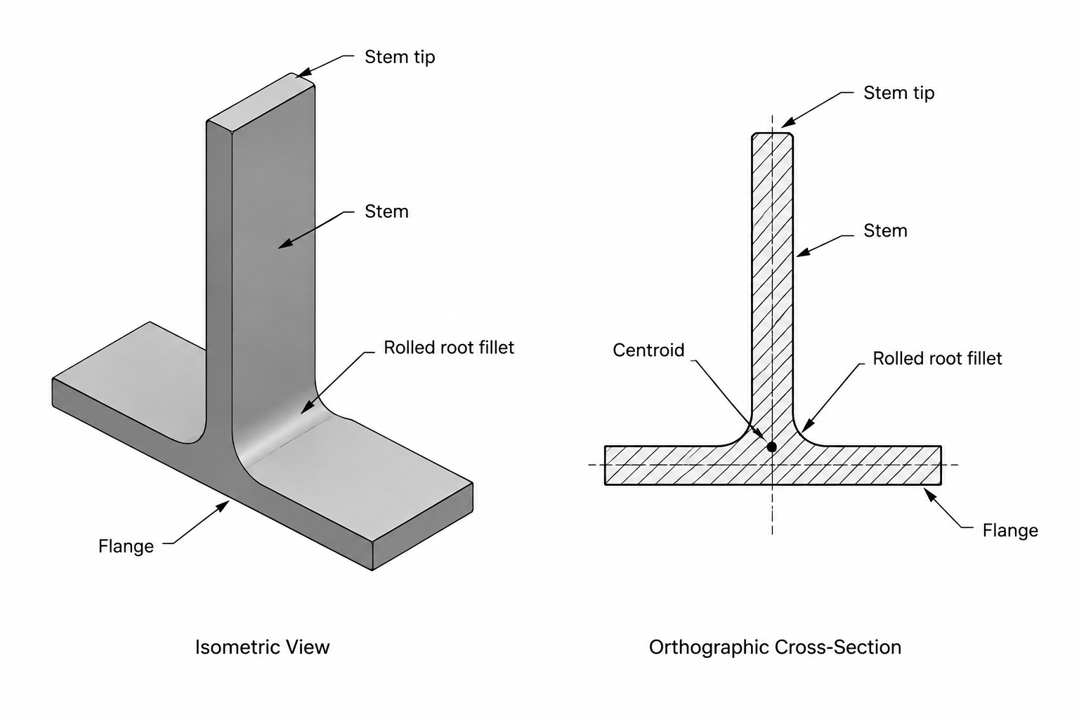
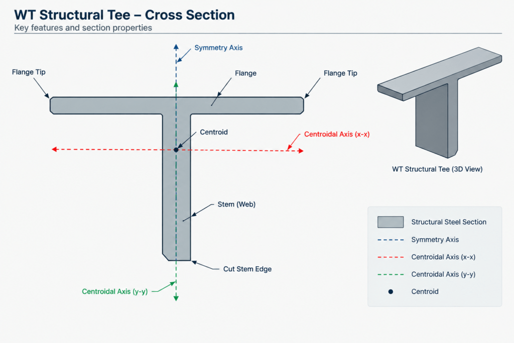
Clear terminology prevents errors when a tee is rotated in a plan, elevation, or detail. The principal geometric parts are:
- Flange: the wide horizontal element in the conventional upright view.
- Stem: the narrower projecting element, inherited from part of the parent web.
- Flange tips: the free edges at either end of the flange.
- Stem tip: the free edge created along the split line.
- Root or fillet region: the curved transition where the stem joins the flange.
Descriptions such as “top,” “bottom,” “left,” and “right” depend on drawing orientation. Notes such as “flange up,” “stem horizontal,” or “stem toward grid line” are more useful when orientation affects a connection.
A WT is singly symmetric. Its symmetry axis passes through the stem centerline and the center of the flange width. The perpendicular centroidal axis is parallel to the flange. When reading section-property tables, verify the axis diagram rather than assuming that screen orientation or CAD coordinates match the published axis labels.
Why the Centroid Is Not at Mid-Depth
The flange concentrates a significant portion of the cross-sectional area near one end of the tee. As a result, the centroid is shifted toward the flange and does not normally lie halfway between the flange surface and the stem tip.
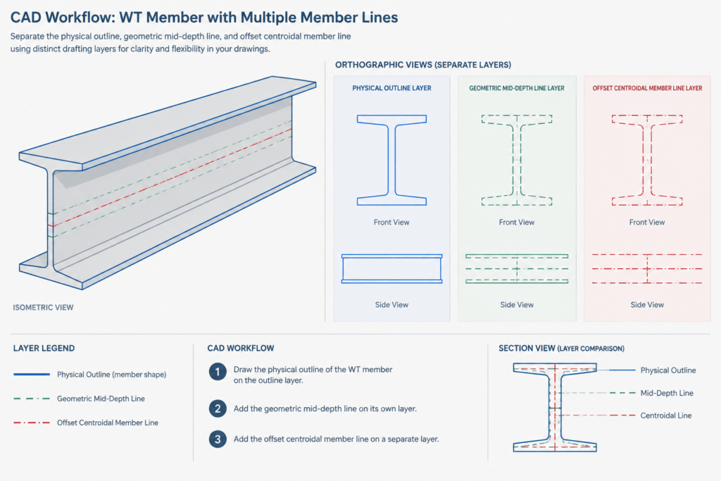
This matters in both analysis and detailing. A member centerline representing the centroidal axis will not coincide with a line drawn at half the overall depth. Likewise, a connection centered geometrically on the stem may not pass through the member centroid. Depending on the load path and restraint, that offset can introduce eccentricity, bending, or torsional effects that require engineering evaluation.
The centroid location also affects section modulus. Distances from the centroid to the flange extreme fiber and to the stem-tip extreme fiber are different. Consequently, the elastic section modulus about the flange-parallel axis generally has different values for the two sides of the section. A table may distinguish these values with plus/minus notation or other labels. Always check the table’s axis sketch and sign convention.
WT Dimensions Used in Detailing
| Dimension or feature | Practical use | Common mistake |
|---|---|---|
| Overall depth | Envelope, fit-up, clearance, and member placement | Using the nominal designation as an exact depth |
| Flange width | Connection layout, bearing, edge clearance, and interference checks | Assuming it matches another tee of similar weight |
| Flange thickness | Fit-up, weld access, bolt grip, and local connection geometry | Drawing the flange as a symbolic line |
| Stem thickness | Bolt and weld layout, slots, copes, and plate alignment | Confusing it with the full parent web thickness plus cutting allowance |
| Centroid location | Analytical member lines and eccentricity checks | Placing the centroid at half-depth |
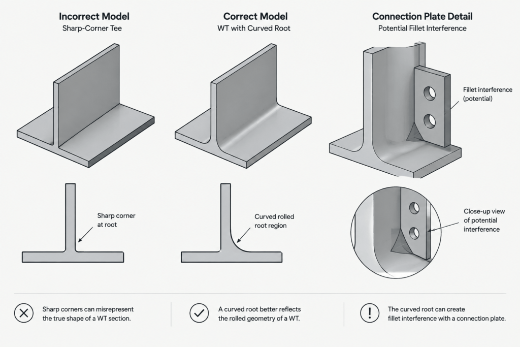
| Fillet or detailing-clearance region | Plate fit-up, weld termination, and clash review | Extending plates into the rolled root geometry |
| Stem-tip condition | Fabrication notes, edge preparation, and exposed-edge treatment | Depicting it as a rolled edge without verification |
Rolled Flange Versus Cut Stem Edge
A split WT combines rolled surfaces with a cut surface. The flange tips and outer flange surfaces come from the parent rolled shape. The stem tip is created during splitting and may have a different edge condition.
This distinction can affect fabrication drawings. A schematic section symbol does not describe cut quality, straightness, surface preparation, edge finishing, or whether additional machining is required. If any of those characteristics are important to the connection or final appearance, they should be addressed by the project documents and fabrication requirements rather than inferred from the WT designation.
Splitting can also release residual stresses and contribute to distortion. Detailers should avoid assuming that two long tees produced from one parent section will remain perfectly straight or geometrically identical without normal fabrication control. Required tolerances, straightening, and fit-up procedures are project and fabricator considerations.
Connection and Clearance Considerations
The inside junction between flange and stem is not a sharp corner. A plate, angle, washer, weld access feature, or other component placed near this region may interfere with the rolled fillet. CAD models that use a sharp rectangular junction can therefore show false clearance.
Connection layouts should consider:
- The actual flange and stem thicknesses from verified shape data.
- The rolled root geometry and any associated detailing-clearance dimension.
- Access for bolts, washers, welding, inspection, and tools.
- The offset between the connection work line and the tee centroid.
- Whether forces enter through the flange, stem, or both.
- Whether the stem tip requires edge preparation or special treatment.
- Possible interference with gusset plates, stiffeners, supporting members, and adjacent fasteners.
A connection that appears centered in a two-dimensional elevation may still be eccentric relative to the tee’s centroid or shear center. The structural significance of that eccentricity must be evaluated by the responsible engineer.
A Practical CAD Workflow for WT Shapes
1. Start with verified shape data
Select the exact WT designation and obtain its dimensions from a reliable shape database or project reference. Do not scale a generic tee symbol or estimate dimensions from the nominal designation.
2. Separate display geometry from analytical geometry
Use a physical outline for plans, sections, elevations, and clash review. If a centroidal member line is also needed, place it on a separate layer or assign it a distinct object style. This prevents a geometric centerline from being mistaken for the analytical axis.
3. Model fillets according to drawing purpose
A simplified outline may be acceptable for a small-scale framing plan. Connection details and fabrication models need enough root geometry to identify real interferences. The level of detail should be deliberate and documented.
4. Define a consistent insertion point
Useful insertion points include the centroid, flange center, stem tip, or an outer flange corner. Record which point the block or component uses. Unlabeled insertion logic can create placement errors when a tee is rotated or mirrored.
5. Preserve orientation information
Include an orientation note or local-axis marker where the flange direction affects design or connection geometry. Check mirrored details carefully; mirroring graphic objects does not automatically resolve member marks, weld symbols, or directional notes.
6. Verify the finished detail
Confirm the designation, overall orientation, centroidal reference, connection clearances, and cut-edge assumptions. A downloaded or reused CAD component should be treated as reference geometry until checked against current project information.
Key Takeaway
A WT is more than half of a wide-flange outline. Its asymmetric depth geometry, shifted centroid, rolled root region, and cut stem edge all influence section properties and detailing. Use the designation to identify the shape, verified tables to obtain dimensions and properties, and project-specific engineering to evaluate loads and connections. In CAD, distinguish the physical outline from analytical centerlines and never assume that nominal depth, mid-depth, and centroid location are the same.