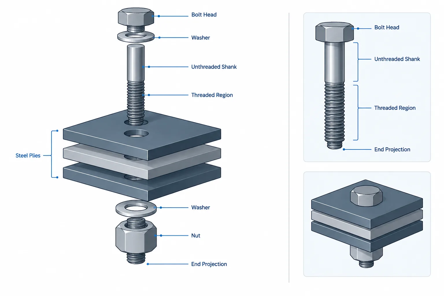
Selecting a structural bolt involves more than matching a diameter to a hole. The detailer must account for every connected ply, required washers, the nut, available thread, bolt-end projection, and the location of threads relative to potential shear planes. A connection may look correct in plan or elevation while still containing an incomplete or unbuildable fastener stack.
This guide explains structural bolt grip length as a detailing and coordination concept. It does not provide project-specific bolt lengths or installation requirements. Those must come from the connection design, governing documents, selected fastener system, and applicable fabrication and erection practices.
What Is Structural Bolt Grip Length?
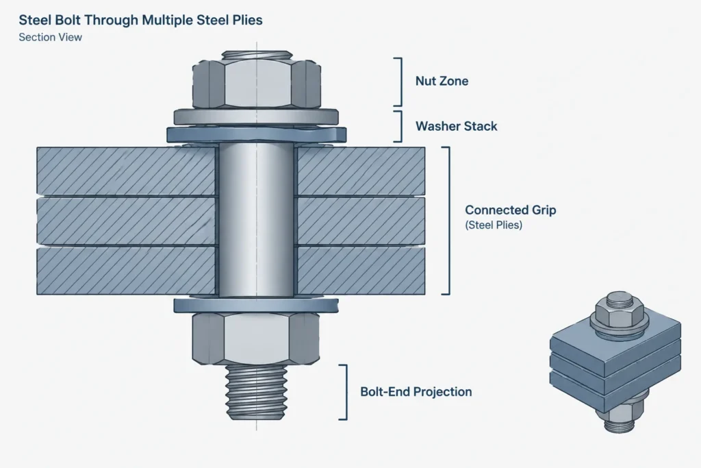
Grip length generally means the combined thickness of the connected steel plies held together by the bolt. In a simple beam connection, the grip might include a beam web and a connection plate. In a splice, it may include splice plates and the member material between them.
Washers are commonly considered separately from the steel grip when selecting the complete bolt length. However, terminology and ordering workflows can vary, so the project team should define what its bolt schedule or software field includes.
A useful conceptual relationship is:
Required bolt length = connected ply stack + washer stack + nut allowance + required end projection and thread allowance
This is a coordination relationship, not a universal sizing formula. The dimensions and increments used for actual selection depend on the specified bolt assembly and project requirements.
Build the Connection as a Stack of Parts
The safest way to evaluate a bolt is to treat the connection as an ordered stack rather than as a line passing through a symbolic hole. Start at the bolt head and identify every component encountered before reaching the nut.
- Bolt head
- Washer under the head, when required
- Outer connected plate or member wall
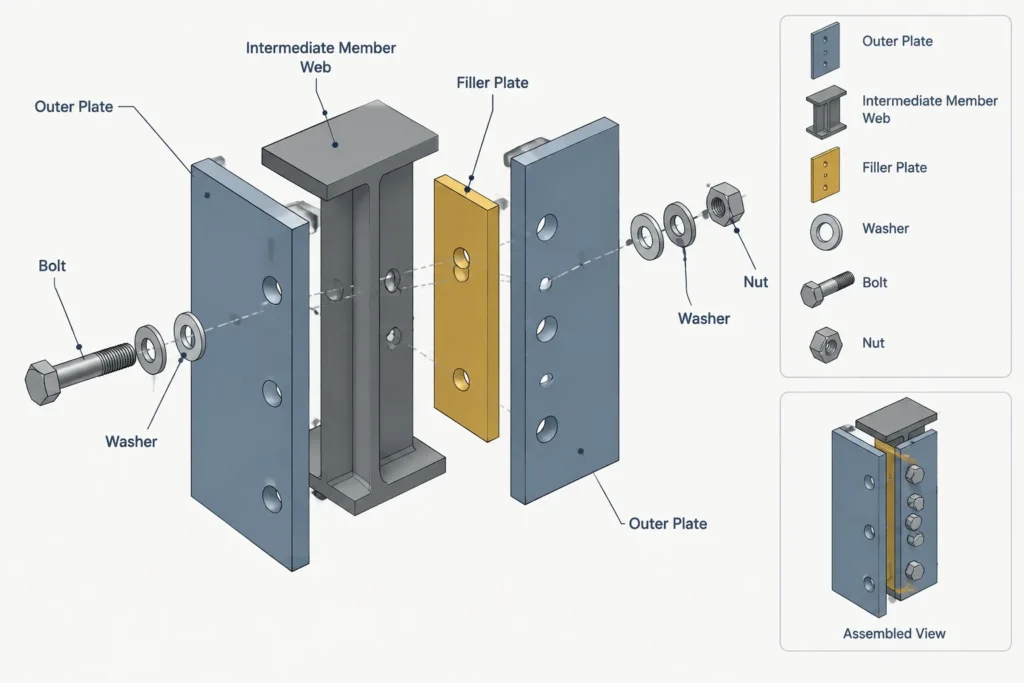
- Intermediate plies, fillers, shims, or member elements
- Opposite outer ply
- Washer or installation component under the nut, when required
- Nut
- Bolt-end projection beyond the nut
Not every assembly contains every item. The purpose of the list is to prevent hidden components from being omitted. A filler plate added during connection development, for example, directly changes the required fastener length even if the bolt pattern remains unchanged.
Typical Ply Combinations
| Connection condition | Possible grip components | Detailing concern |
|---|---|---|
| Single-plate beam connection | Connection plate and beam web | Confirm plate side, web thickness, and access to the nut |
| Double-angle connection | Angle leg, member web, and opposite angle leg | Account for both angles and any erection gap or fit condition |
| Flange splice | Outer splice plate, flange, and any inner plate | Check changing flange thickness and interference near web fillets |
| Web splice | Splice plate, web, and opposite splice plate | Keep the modeled stack consistent on both sides |
| HSS through-bolt condition | Near wall, internal space or hardware, and far wall | Do not treat the outside HSS dimension as solid steel grip |
| Built-up connection | Multiple plates, fillers, and member elements | Review each bolt row because the stack may vary by location |
Grip Is Not the Same as Bolt Length
A common drafting error is to use total ply thickness as the bolt length. The bolt must also accommodate any washers and installation components, the nut, and the required projection beyond the nut. At the same time, excessive length can create unwanted protrusion, clashes, or a condition in which the nut reaches an unsuitable portion of the bolt.
The selected assembly should be checked as a system. A bolt that is long enough to pass through the connection is not automatically suitable. The available thread, unthreaded shank, thread runout, and installed nut position all matter.
Why Thread Location Matters
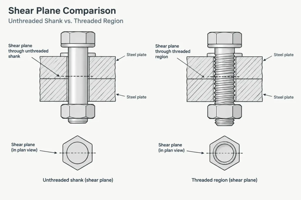
Structural drawings and calculations may distinguish between a shear plane passing through the unthreaded shank and one passing through the threaded portion. This is a design assumption, not merely a shop preference. A substitution that changes bolt length or thread geometry can affect whether that assumption remains valid.
The detailer should not infer thread location from a generic bolt symbol. Instead, coordinate the specified fastener type and length with the actual ply stack. If the design requires threads to be excluded from a shear plane, that intent should be communicated clearly enough for procurement, fabrication, and inspection to recognize it.
Potential shear planes occur at interfaces between connected plies. A multi-ply connection can have more than one such interface, so checking only the face under the bolt head is insufficient.
Washers and Installation Components
Washer requirements depend on the fastener assembly, hole condition, connected surface, installation method, and governing project criteria. A detail should not add or remove washers simply to make a preferred bolt length work.
Possible stack components include hardened washers, plate washers, direct-tension indicators, or other specified installation elements. Their placement matters because moving a component from the nut side to the head side changes the physical assembly and may affect access or inspection even when the overall stack thickness is similar.
Sloped surfaces, tapered flanges, slots, oversized holes, and surfaces near rolled fillets deserve special review. The required bearing condition and washer arrangement must be established from the connection requirements rather than assumed from a typical detail.
Common CAD and Detailing Mistakes
- Modeling bolts as fixed-length library objects: A reusable block may preserve an old length after the connected plate thickness changes.
- Ignoring hidden plies: Fillers, shims, reinforcing plates, or the far wall of a member may be absent from the visible view.
- Using nominal member depth as grip: A hollow or open section must be evaluated from the actual material crossed by the bolt.
- Assuming every bolt in a group has the same stack: Local plates, flange transitions, or stepped surfaces can create different grip conditions.
- Showing washers graphically but omitting them from the material logic: The drawing and bolt list then describe different assemblies.
- Changing length without checking threads: A longer or shorter bolt can move the thread runout relative to a shear plane or nut.
- Overlooking tool clearance: A dimensionally valid assembly may still be difficult to install if the head or nut is obstructed.
A Practical Bolt-Length Coordination Workflow
Identify the fastening condition
Determine which members and plates are being joined, the bolt diameter and assembly specified by the design, the hole condition, and whether the connection has special installation requirements.
Trace each bolt through the section
Use a section or three-dimensional view to follow the bolt from head to nut. Record each steel ply independently. Do not rely solely on a plan-view symbol.
Add non-ply components
Identify washers and other installation components by side. Keep these separate from the connected-steel grip so revisions are easier to audit.
Check thread and shank placement
Compare the anticipated thread geometry with each potential shear plane and with the final nut position. Escalate any conflict with the design assumption rather than resolving it through an undocumented substitution.
Review access and projection
Check whether the bolt can be inserted and whether the nut can be installed and tightened. Review nearby flanges, stiffeners, HSS walls, deck, concrete, and adjacent bolts. Also check whether projecting bolt ends conflict with finishes, equipment, or other trades.
Synchronize drawings and lists
The model, connection detail, bolt schedule, bill of material, and shop notes should describe the same assembly. If bolt lengths are assigned later by the fabricator, the drawings should still contain enough accurate geometry to support that process.
When Connection Geometry Changes
Bolt grip should be rechecked whenever a connected thickness changes. Common triggers include a revised beam size, a thicker connection plate, an added doubler, a new filler, a change in washer arrangement, or conversion from a one-sided to a two-sided connection.
Changing only the bolt pattern does not necessarily change grip, while changing a plate thickness does. This distinction is useful in CAD revision workflows: geometry that affects stack thickness should be flagged separately from changes affecting spacing or quantity.
What the Drawings Should Communicate
Shop drawings do not always need to dimension every part of the bolt stack, but they should remove ambiguity. Depending on the project workflow, useful information may include the fastener designation, bolt length, quantity, hole type, washer arrangement, installation side, and any thread-location requirement established by the design.
Generic bolt graphics should never be treated as proof that the assembly has been checked. The reliable approach is to connect the graphical detail to verified member thicknesses, plate data, and fastener information.
Final Review Checklist
- Are all connected steel plies included?
- Are fillers, shims, and hidden plates accounted for?
- Are washers and installation components shown on the correct side?
- Does the selected length accommodate the nut and required projection?
- Is thread location consistent with the connection design?
- Can the bolt be inserted, tightened, and inspected?
- Do the detail, model, and material list agree?
- Has the stack been rechecked after member or plate revisions?
Structural bolt grip length is a small dimension with broad coordination consequences. Treating the fastener as a complete assembly—rather than a symbol through a hole—helps prevent procurement errors, thread-location conflicts, field fit problems, and mismatches between drawings and material lists.