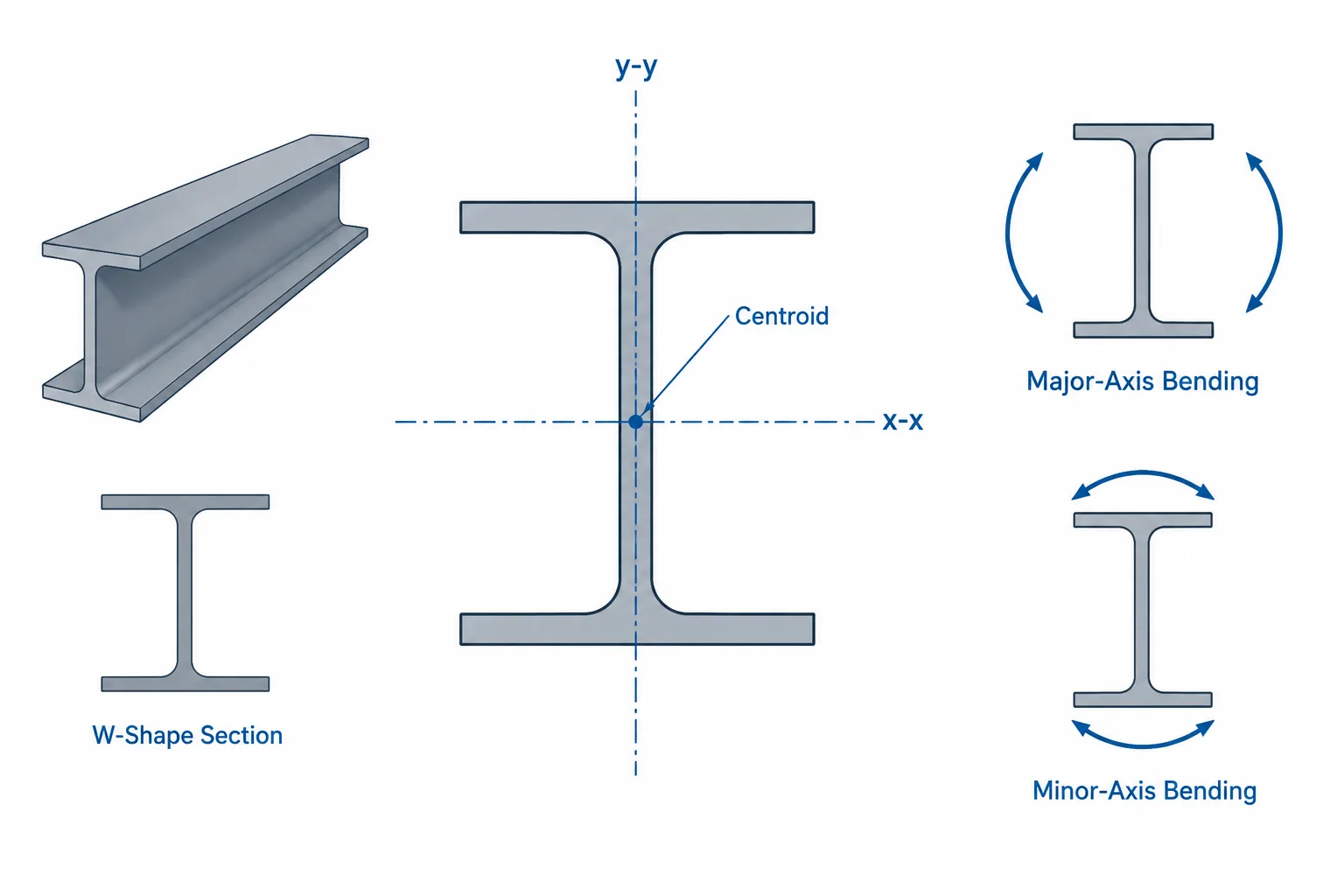
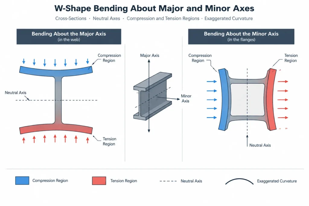
Strong-axis and weak-axis bending describe how a structural steel cross-section responds when bending occurs about different centroidal axes. The distinction is especially visible in W-shapes, where material concentrated in the flanges produces much greater bending stiffness about one axis than the other.
These terms are useful, but they can also cause confusion. A member does not have a permanently horizontal strong axis or a permanently vertical weak axis. The axes rotate with the cross-section, and their relationship to the building depends on how the member is oriented. Reliable interpretation therefore requires checking the section diagram, axis labels, member rotation, and direction of loading together.
What Makes One Axis Stronger?
The bending stiffness of a steel section depends partly on its area moment of inertia about the axis of bending. For a prismatic member of one material, the flexural rigidity is expressed as EI, where E is the material’s elastic modulus and I is the section’s area moment of inertia.
Because the material is the same in both directions, the section’s geometry creates the difference between its strong- and weak-axis response. Material located farther from the bending axis contributes more strongly to I. In a typical W-shape orientation:
- The x-x axis passes through the centroid and is parallel to the flanges.
- The y-y axis passes through the centroid and is generally aligned with the web.
- Bending about x-x mobilizes the flange area at a comparatively large distance from the axis.
- Bending about y-y distributes the flange widths on either side of an axis running through the web.
As a result, the published Ix is normally larger than Iy for a conventional W-shape. This is why x-x is commonly called the major or strong axis and y-y the minor or weak axis.
Axis conventions should still be verified in the source being used. CAD families, analysis applications, shape databases, and imported models may assign local axes differently even when the physical geometry is correct.
How Ix, Iy, Sx, and Sy Relate
Several section properties are reported for each principal direction. They describe related behavior but are not interchangeable.
| Property | General meaning | Typical use |
|---|---|---|
| Ix, Iy | Area moment of inertia about the indicated axis | Elastic deflection, stiffness, and stability calculations |
| Sx, Sy | Elastic section modulus for bending about the indicated axis | Elastic bending stress relationships |
| Zx, Zy | Plastic section modulus about the indicated axis | Plastic section behavior when permitted by the applicable design method |
| rx, ry | Radius of gyration about the indicated axis | Member slenderness and buckling checks |
For elastic bending, stress varies with distance from the neutral axis. Section modulus incorporates both the moment of inertia and the distance to an extreme fiber. Consequently, a larger value of I does not eliminate the need to read the corresponding value of S when checking bending stress.
The subscripts identify the axis about which bending occurs, not the direction in which the member visibly deflects. Bending about the x-x axis creates curvature in the plane perpendicular to that axis. This distinction matters when translating an analysis result into an elevation, section, or model view.
Strong and Weak Axes in Common Steel Shapes
W-Shapes and Other I-Sections
W-shapes have a pronounced difference between their major- and minor-axis properties. In a common floor-beam orientation, the web is vertical and gravity loading primarily produces major-axis bending. If that same section is rotated so the web is horizontal, its local strong axis rotates with it. The building’s vertical direction does not redefine the section axes.
S-shapes and HP shapes also have two principal centroidal axes, although their proportions and intended applications differ. Shape-family assumptions should never replace the actual published properties for the selected designation.
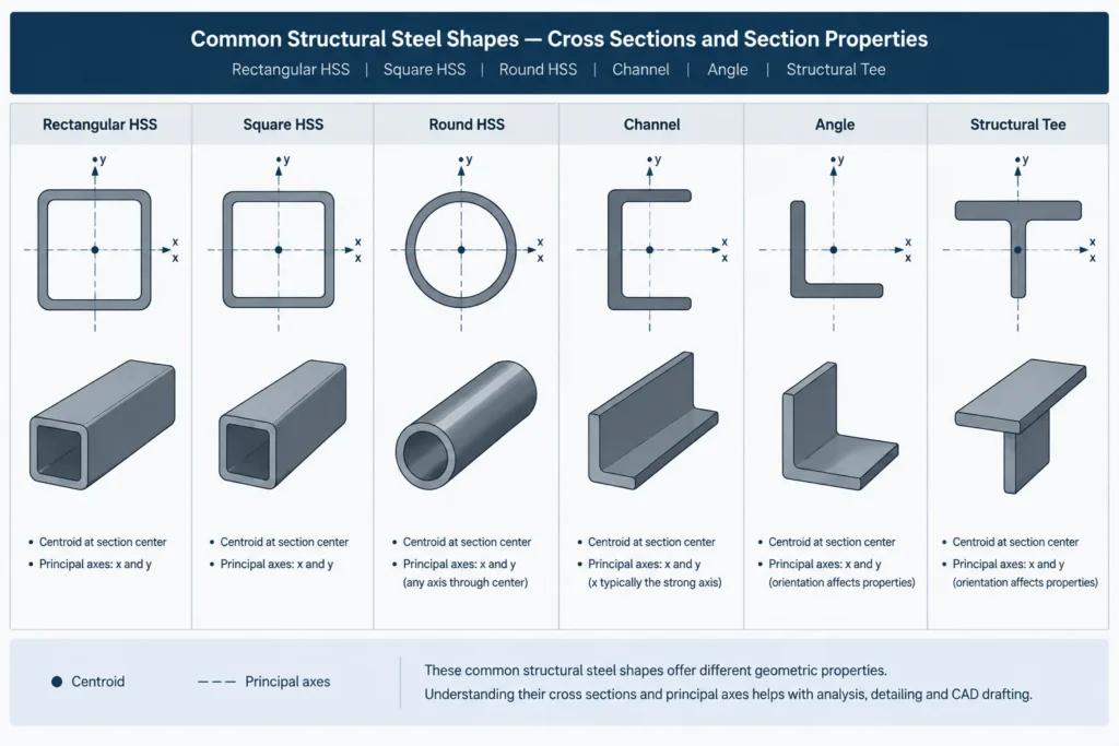
Rectangular and Square HSS
A rectangular HSS generally has different section properties about its two centroidal axes. The direction associated with the greater overall section depth will commonly have the larger moment of inertia, assuming the wall geometry is otherwise consistent.
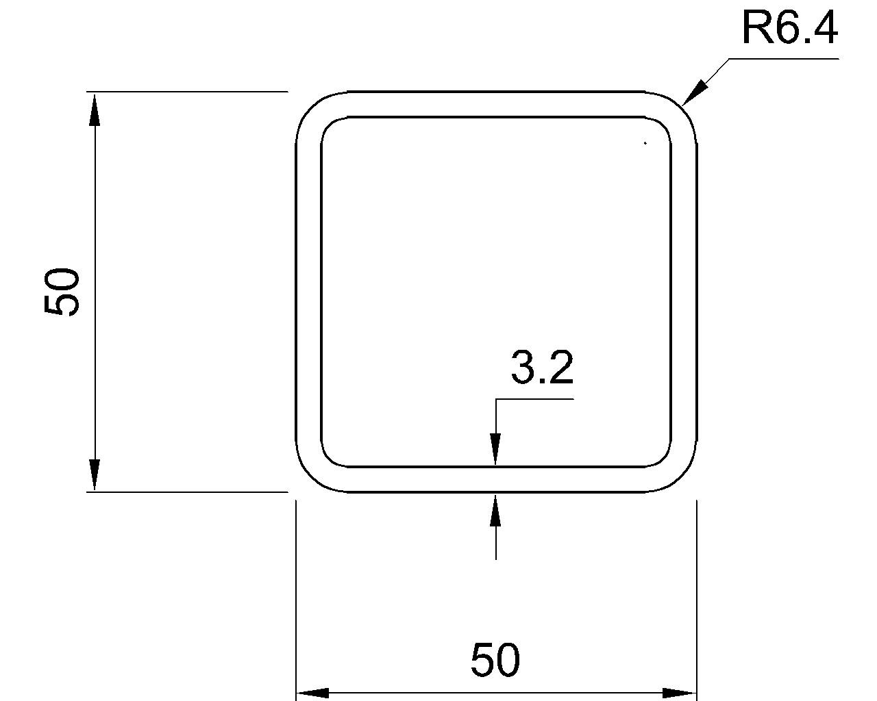
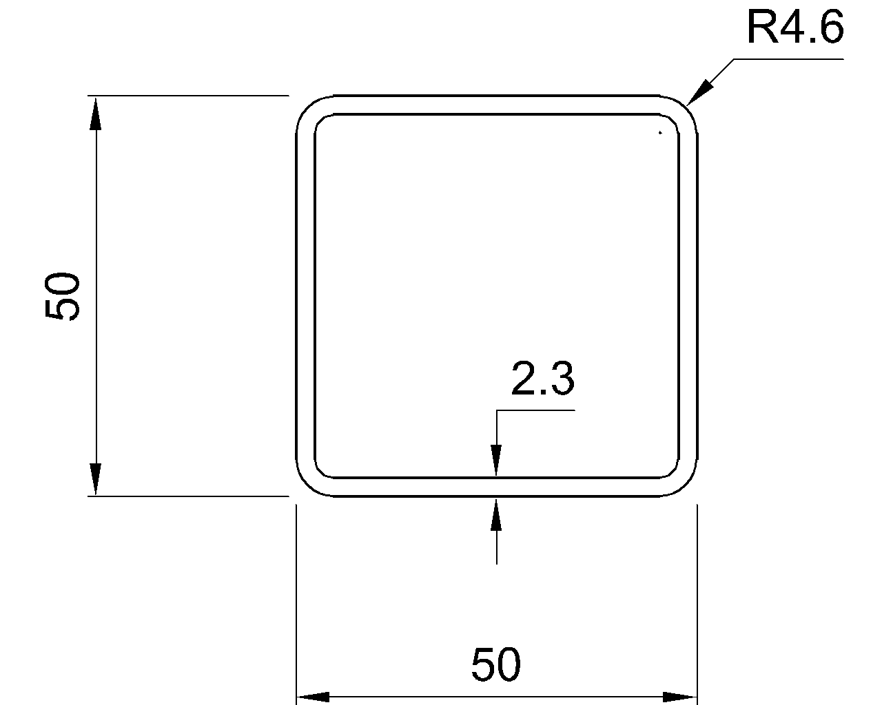
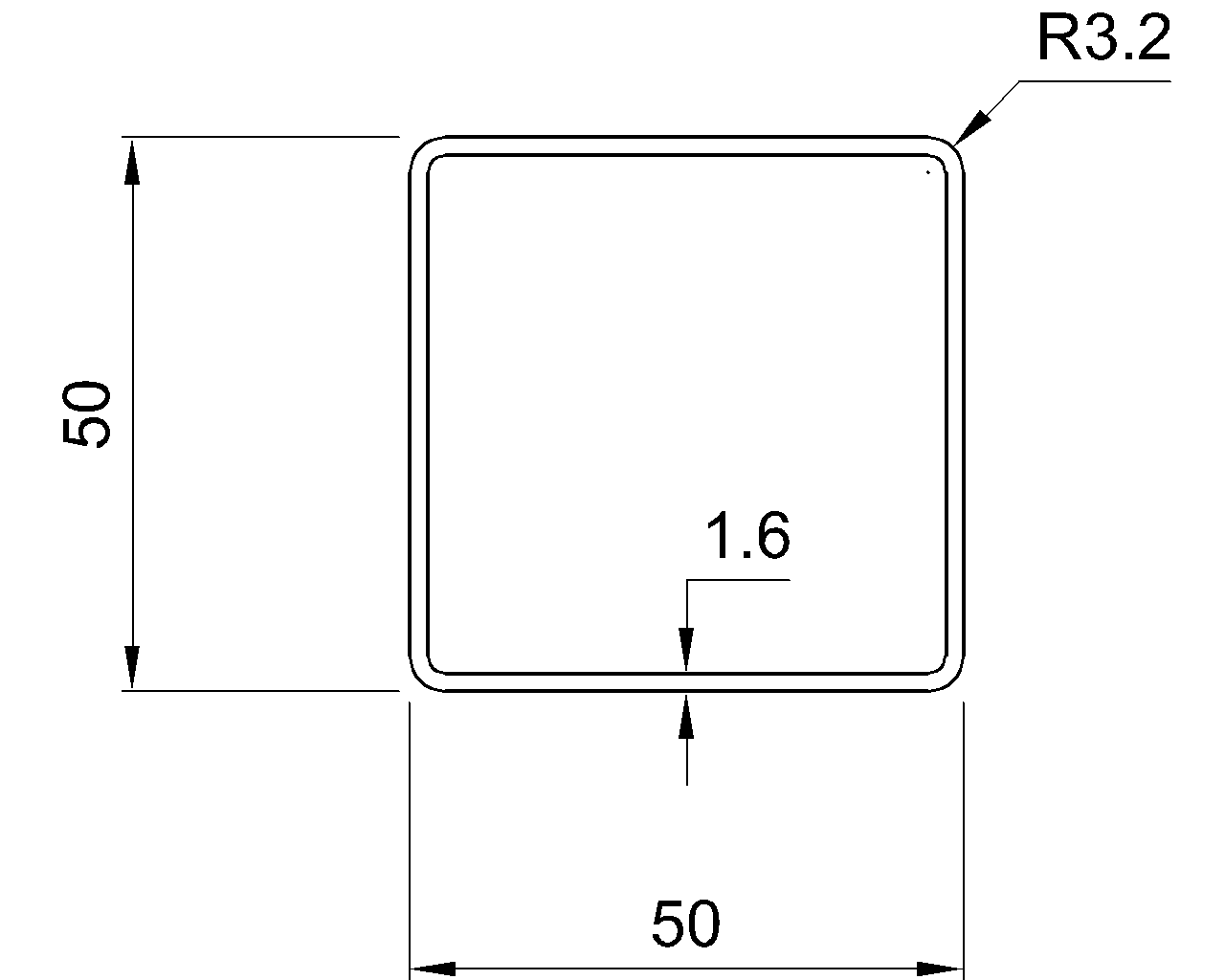
A square HSS has equal nominal properties about its two geometric centroidal axes. That does not mean every real member condition is directionally identical. Connections, holes, welds, supports, attached plates, loading eccentricity, and unbraced lengths can introduce directional differences that are not represented by the bare cross-section properties.
Round HSS and Pipe-Shaped Sections
A circular cross-section has the same nominal bending properties about any centroidal diameter. For such a section, the labels strong axis and weak axis generally do not distinguish the undeformed cross-section itself. Member behavior may still be directional because of connections, support conditions, imperfections, or applied loading.
Channels, Angles, and Tees
Channels and structural tees have recognizable major and minor centroidal directions, but they also require attention to shear-center location and torsional response. An angle’s geometric reference axes may not be its principal axes. For unsymmetric sections, bending applied in a convenient horizontal or vertical direction can resolve into bending about both principal axes.
This is one reason that strong-axis versus weak-axis shorthand is most straightforward for doubly symmetric sections. For channels, angles, and other unsymmetric shapes, the complete axis and loading definition is more informative than a simple strong or weak label.
Weak-Axis Bending Is Not the Same as Torsion
Weak-axis bending and torsion are different actions. Weak-axis bending is flexure about the section’s minor centroidal axis. Torsion is rotation caused by torque about the member’s longitudinal axis.
The two can occur together. For example, loading applied away from a channel’s shear center can produce bending plus twist. Calling all visible rotation “weak-axis bending” can hide the actual load path and lead to the wrong section properties being reviewed.
Why the Strong Axis Does Not Determine Capacity by Itself
A larger moment of inertia or section modulus does not by itself establish a member’s allowable or design strength. Actual behavior can depend on several additional factors:
- Unbraced length and restraint conditions
- Lateral-torsional buckling behavior
- Local slenderness of flanges, webs, or HSS walls
- Member end conditions and continuity
- Combined axial force and bending
- Load eccentricity and torsion
- Connection stiffness and load introduction
- Openings, copes, holes, reinforcement, or other section modifications
“Strong axis” is therefore a geometric comparison, not a complete capacity statement. Design checks must use the applicable project criteria, verified section data, and actual member conditions.
Reading Axis Orientation in CAD and Structural Models
A correct shape designation can still be modeled with the wrong rotation. This often happens when a member is inserted using a default local coordinate system or when geometry is exchanged between applications.
A practical model check should include the following:
- Display the member’s local axes rather than relying only on the global coordinate system.
- Confirm which local axis corresponds to the published section x-x and y-y directions.
- Inspect the section graphically at several member locations.
- Check the web and flange orientation in plan, elevation, and section views.
- Verify that section-property assignments rotate with the physical member.
- Review offsets and insertion points, which can make a correctly rotated member appear misplaced.
- Confirm that releases, bracing assignments, and applied loads use the intended local directions.
For sloped or skewed framing, screen-horizontal and screen-vertical directions may have little connection to the member’s local axes. A section cut normal to the member centerline is often the clearest verification view.
Drafting Practices That Reduce Axis Confusion
Shop and design drawings usually communicate orientation more reliably through geometry than through unexplained strong-axis or weak-axis notes. Useful indicators include:
- Section views showing the web and flange arrangement
- Top-of-steel or centerline elevations
- Web-direction or open-side orientation notes where needed
- Connection plates that make the intended face clear
- Member marks tied to orientation-controlled details
- Local-axis graphics in analysis or coordination exhibits
If an axis label is used, show or define the relevant coordinate convention. A note such as “bending about y” is incomplete when different project files use different local-axis assignments.
A Practical Verification Sequence
When reviewing strong- and weak-axis behavior, start with the physical shape rather than the property labels alone:
- Identify the exact shape and confirm its cross-sectional geometry.
- Locate the centroidal axes on the source section diagram.
- Match each published property to its stated axis.
- Confirm the section rotation in the model or drawing.
- Determine the actual direction and location of loading.
- Check whether torsion, biaxial bending, or stability effects are also present.
- Verify that calculations and model outputs use the same axis convention.
This sequence prevents a common error: selecting the correct property from a table but applying it to the wrong physical direction. Strong-axis and weak-axis terminology is most valuable when it remains tied to verified section geometry, clearly defined local axes, and the real load path.