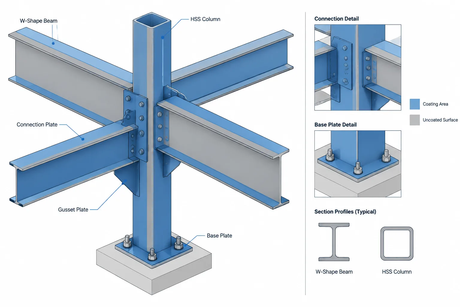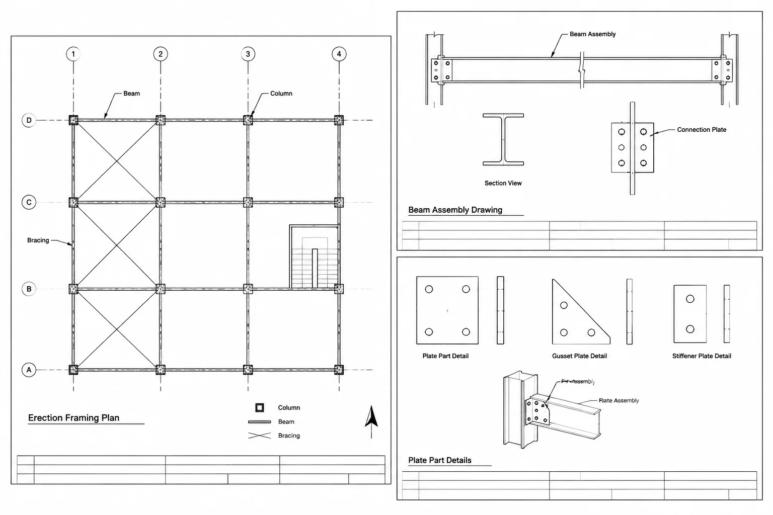
Structural steel shop drawings are not a single type of document. A typical drawing package may include assembly drawings, individual part drawings, erection plans, erection elevations, connection details, and material reports. Each document serves a different production or coordination task, even when several drawings show the same beam, column, plate, angle, or HSS member.
Understanding this drawing hierarchy helps drafters place information where it belongs, helps checkers identify conflicting dimensions, and helps fabricators and erectors find the instructions that control their work. Terminology and document organization vary among fabricators, so project procedures should always take precedence over general conventions.
The basic document hierarchy
Structural design drawings describe the intended structure, member layout, design requirements, and project geometry. Steel shop drawings translate that information into documents used to fabricate and erect individual steel assemblies. They do not replace the design documents or authorize unreviewed changes to the structure.
Within the shop drawing package, information is commonly divided according to three practical questions:
- What must be made? Part drawings define plates, angles, tees, stiffeners, and other individual components.
- How must the pieces be joined? Assembly drawings describe a fabricated member and the parts attached to it.
- Where does the completed member go? Erection drawings locate assemblies in the structure.
A useful detailing system keeps these roles distinct while providing enough cross-referencing to follow a component from raw material to its final position.
Assembly drawings
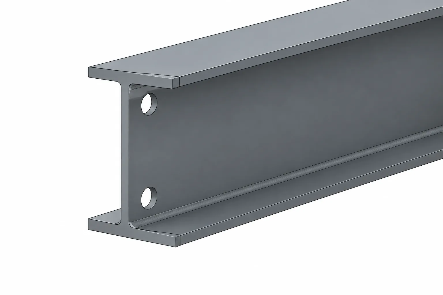
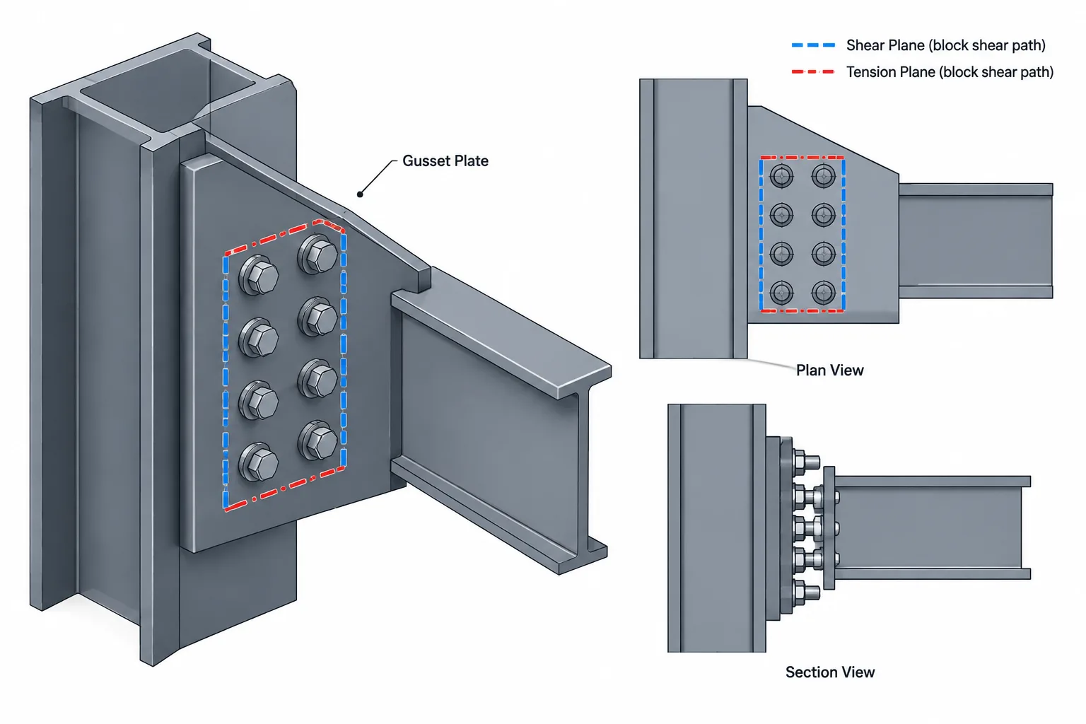
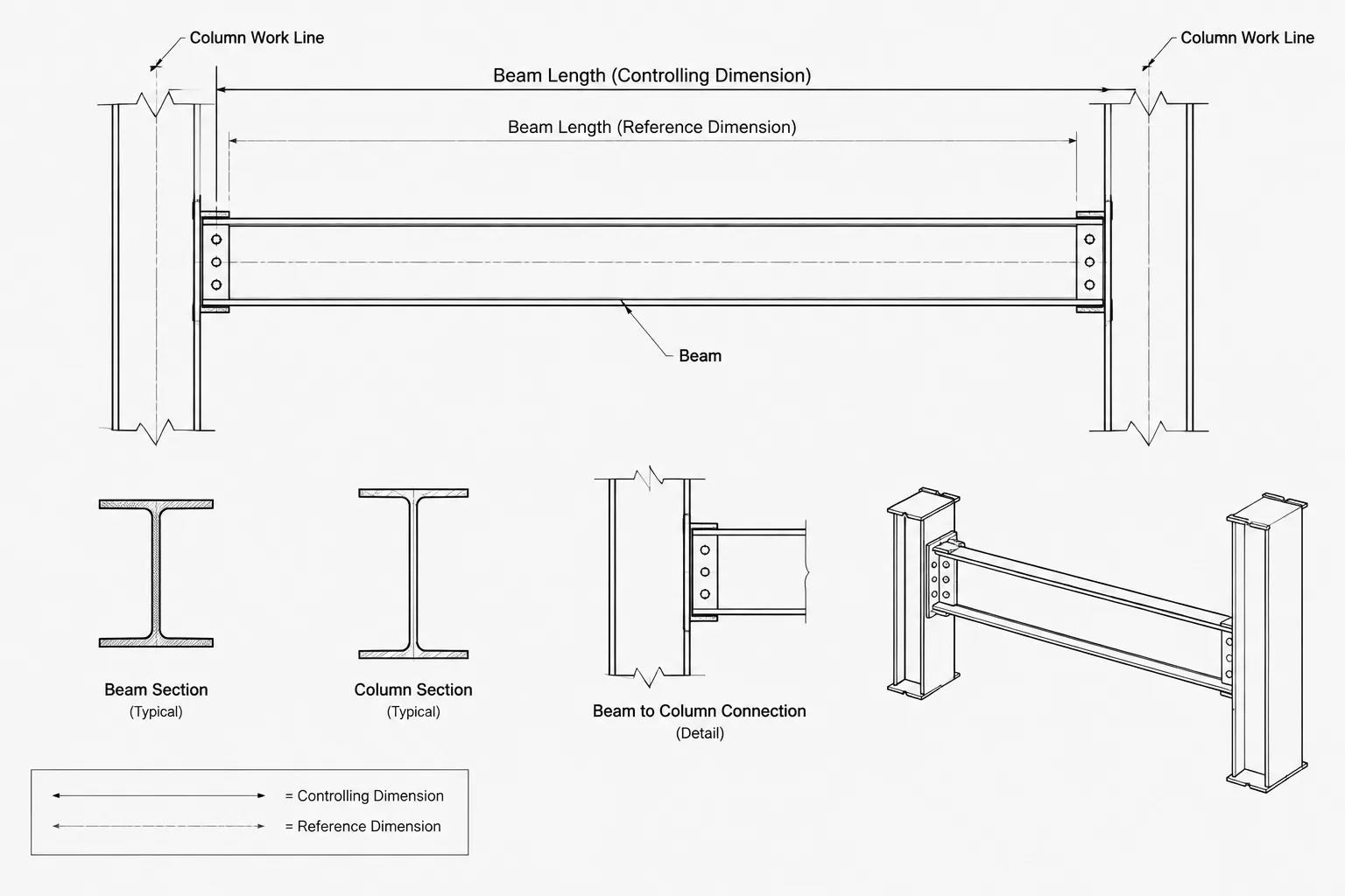
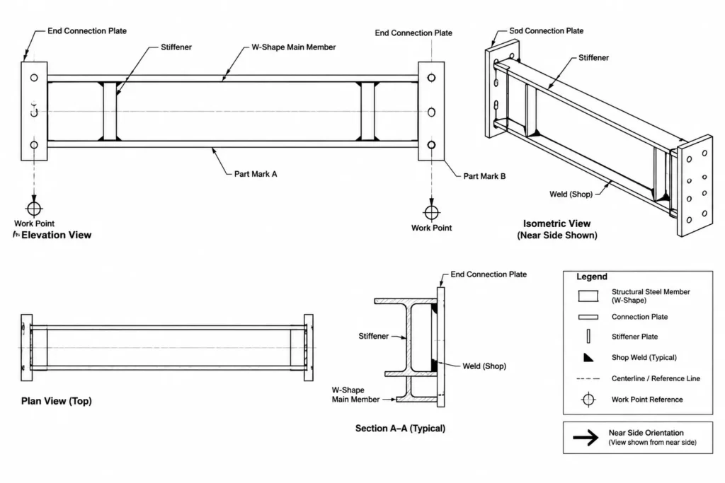
An assembly drawing—sometimes called a detail sheet or member detail—shows a fabricated unit that will normally receive an assembly or shipping mark. Examples include a beam with end connections, a column with base and cap plates, a bracing member with gusset attachments, or an HSS frame welded together in the shop.
The assembly drawing usually establishes the member’s fabrication geometry. Depending on company practice, it may show:
- The main member shape and assembly mark
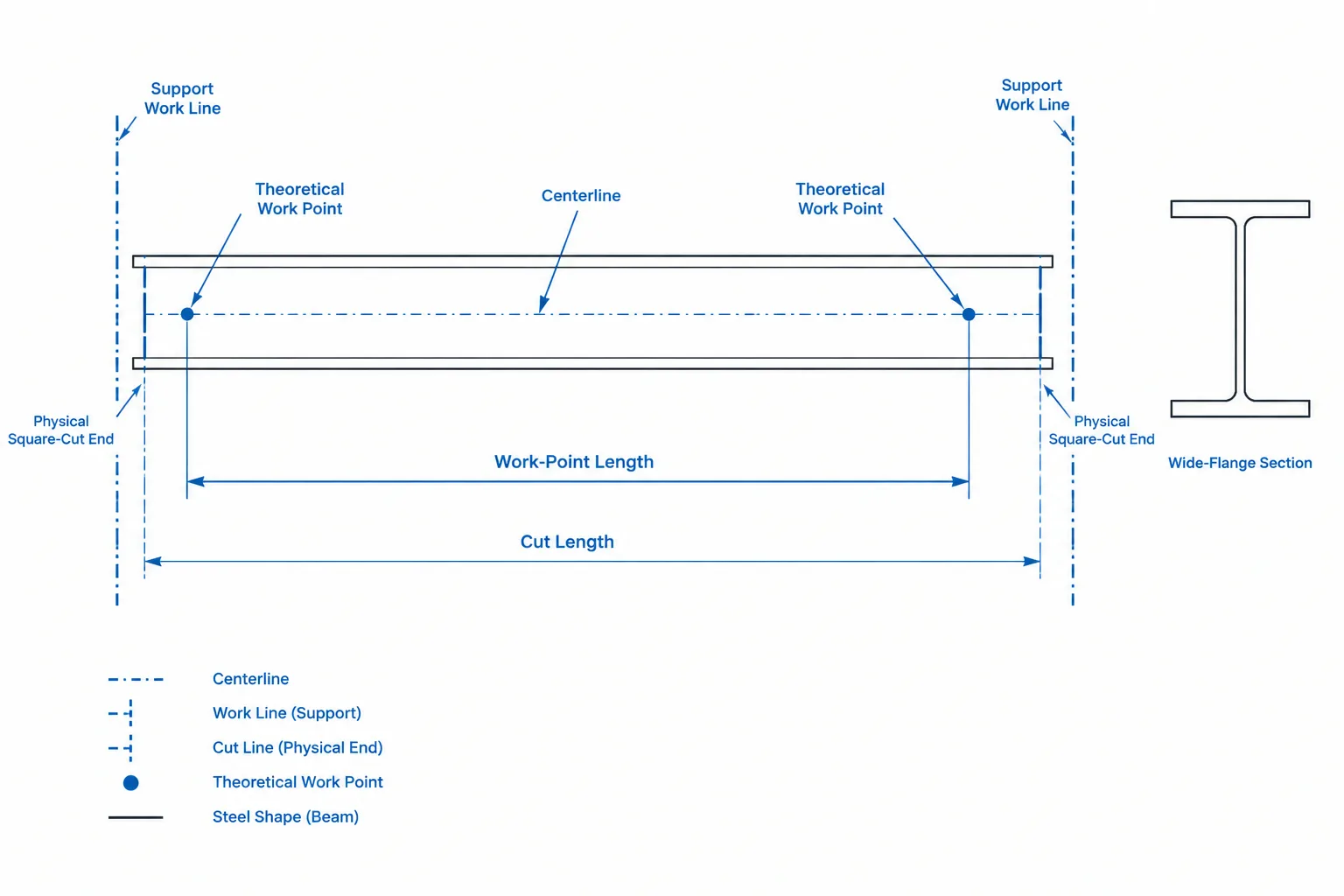
- Overall, work-point, or controlling member lengths
- End setbacks, slopes, skews, and cut conditions
- Attached plates, angles, stiffeners, seats, clips, or connection material
- Bolt-hole locations and hole descriptions
- Shop weld locations and weld information
- Part marks for attached components
- Orientation indicators such as top, north, near side, or far side
- Section cuts and enlarged details needed to clarify congestion
The assembly drawing should communicate how the parts relate to the main member. A loose plate may be fully defined on its part drawing, while the assembly drawing controls where that plate is positioned and attached.
Dimension from stable references
Assembly dimensions should originate from references that remain meaningful during fabrication. Depending on the member, these may include a work point, member end, column centerline, beam centerline, top of steel, face of web, or back of angle.
Dimensions should not force the shop to reconstruct critical geometry by adding several unrelated values. If the location of a connection affects fit-up with another member, the controlling relationship should be clear. Informational dimensions may be useful, but they should not compete with the dimensions that govern fabrication.
Part drawings
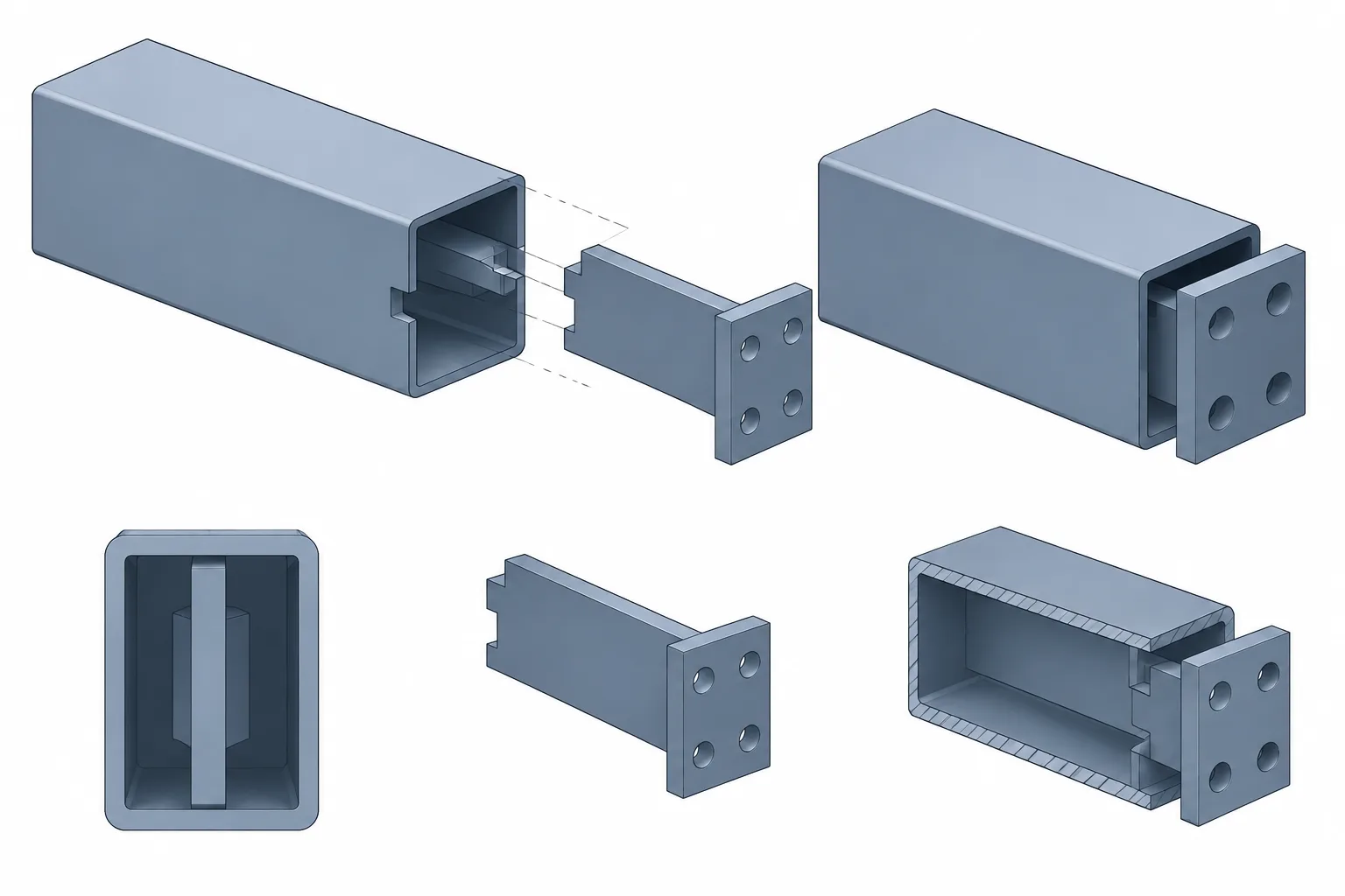
A part drawing defines an individual component before it is incorporated into an assembly. Typical detailed parts include connection plates, base plates, stiffeners, gussets, clip angles, bent plates, web plates, and miscellaneous cut shapes.
Part drawings are often generated as separate sheets or organized into a part-detail area. Their purpose is to support cutting, drilling, punching, coping, bending, and other preparation operations.
A complete part definition may require:
- Part mark and material description
- Thickness or shape designation
- Overall cut dimensions
- Hole layout referenced to identifiable edges or centerlines
- Bevels, clips, notches, radii, or curved boundaries
- Bend lines and orientation where applicable
- Quantity and assembly references
- Views sufficient to distinguish the correct face and handedness
Complex plates should not depend on visual scaling from a drawing. Their geometry must be communicated through controlling dimensions, coordinates, an approved digital workflow, or another clearly defined fabrication method. If CNC data or CAD geometry accompanies the drawing, the project team should establish which source governs and how revisions are synchronized.
Avoiding ambiguous plate orientation
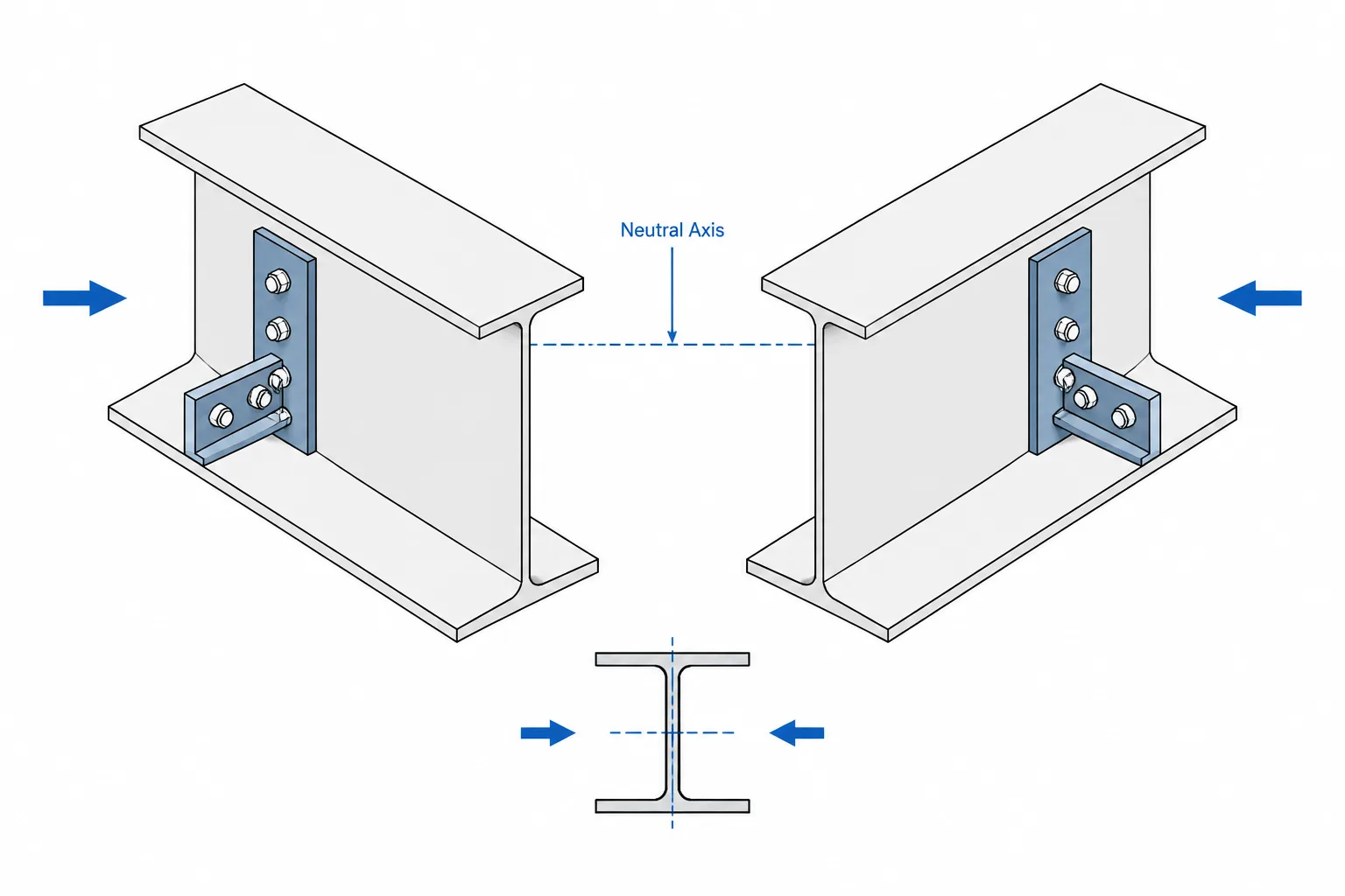
Part drawings can become ambiguous when a plate appears symmetrical but has holes, bevels, or weld preparations on only one face. Labels such as near side and far side are useful only when the viewing direction is unmistakable. A section, face identifier, bend direction symbol, or isometric view may communicate the condition more reliably.
Handed parts need particular attention. A mirrored component may require a different part mark if it cannot be rotated or flipped to serve the same function. The decision should be based on actual geometry, hole orientation, weld preparation, and assembly use—not merely on whether two flat views look similar.
Erection drawings
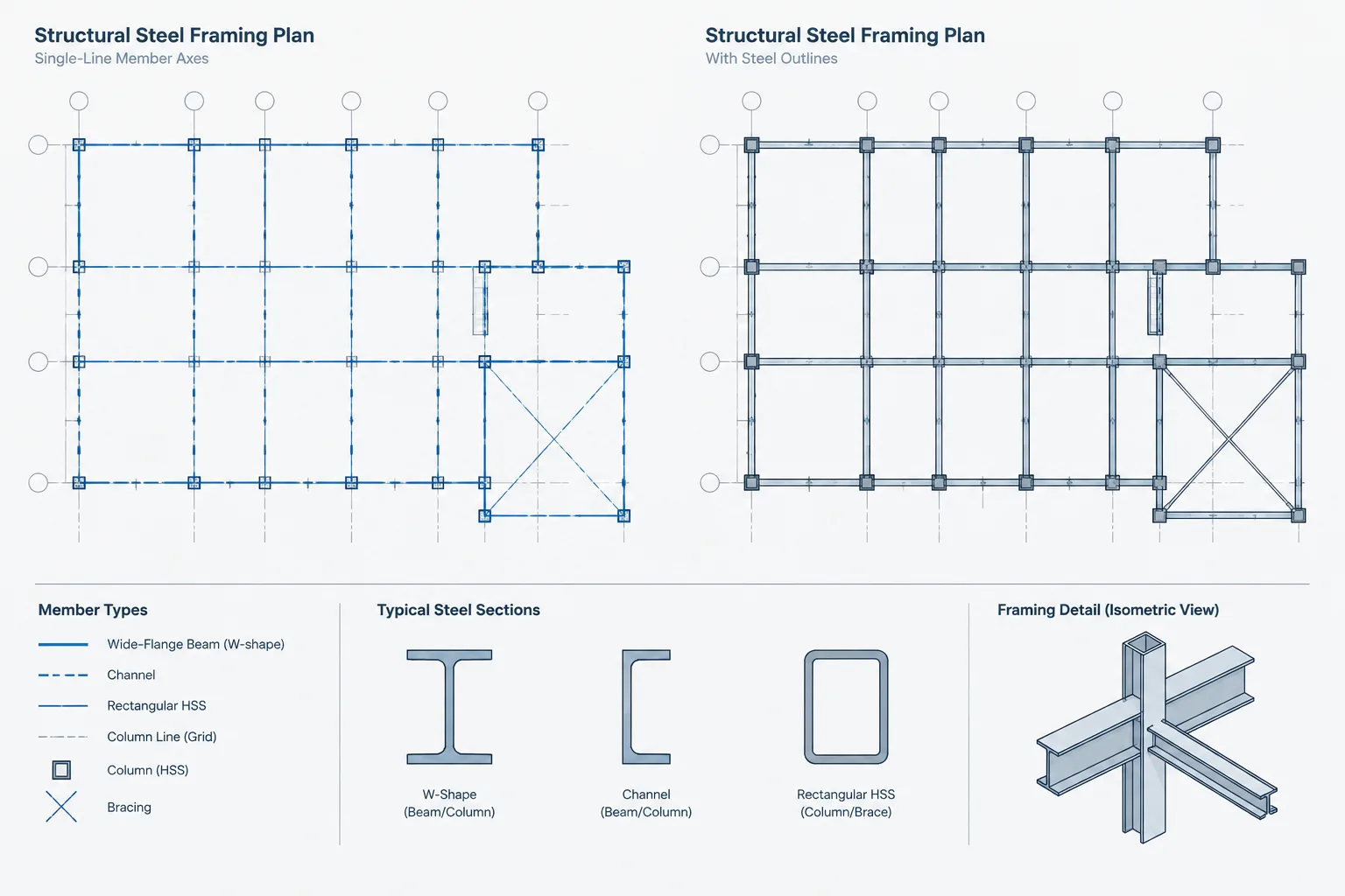
Erection drawings show where completed steel assemblies are installed. Common examples include column plans, beam framing plans, bracing elevations, bent elevations, and miscellaneous steel layout sheets.
An erection drawing generally emphasizes:
- Grid lines and structural reference locations
- Assembly marks corresponding to shop details
- Member orientation and direction
- Top-of-steel or other controlling elevations
- Field connection locations
- Splices, bracing bays, and sequence-sensitive conditions
- Sections and elevations that clarify vertical relationships
- References to relevant details or project documents
Erection drawings are usually less concerned with the manufacturing dimensions of an attached plate. Their job is to let the field identify, orient, and place the completed assembly. Adding every shop dimension to an erection plan can make the layout harder to read and create duplicate sources of information.
Orientation must survive the drawing transition
A member may appear in one direction on an erection plan and in another orientation on its assembly detail. The relationship must remain traceable. Direction arrows, grid references, end labels, flange orientation, and consistent viewing conventions reduce the chance of a member being fabricated or installed backward.
This is especially important for members with offset connections, unequal end conditions, one-sided stiffeners, sloped seats, skewed end plates, or field attachments on only one face.
How the drawing types divide responsibility
| Drawing type | Primary purpose | Typical controlling information |
|---|---|---|
| Assembly drawing | Fabricate a complete marked member | Main-member length, attachment locations, holes, shop welds, end geometry, orientation |
| Part drawing | Produce an individual component | Cut size, thickness or shape, hole pattern, edge geometry, bends, face-specific work |
| Erection drawing | Place completed assemblies in the structure | Grid location, elevation, assembly mark, member direction, field connection location |
| Connection or typical detail | Clarify a recurring configuration | Arrangement, components, attachment concept, and referenced project requirements |
The exact boundary between these drawing types is not universal. Some fabricators place complete part geometry directly on assembly sheets. Others use automated part sheets and keep assembly drawings focused on fit-up. The important principle is that every fabrication requirement has one clear controlling source.
Managing duplicated information
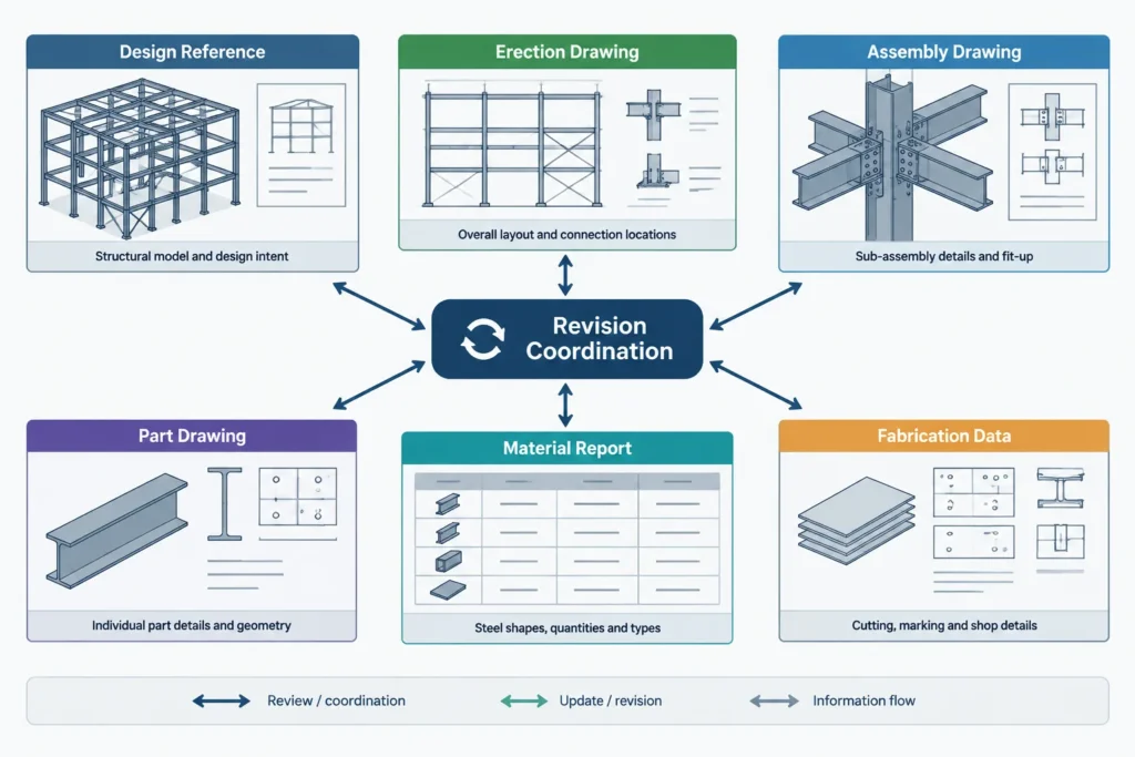
Some duplication is unavoidable. An attached plate mark may appear on an assembly drawing, its own part drawing, a material list, and a production report. Problems arise when the same controlling dimension is entered independently in several places.
When duplicated values are necessary, they should come from a coordinated model or data source whenever possible. Manual overrides require special care because a later model revision may update one drawing but leave another unchanged.
A checker should look for conflicts such as:
- A part size that differs between the part detail and assembly material list
- Hole spacing that changes between views
- An erection mark assigned to the wrong assembly
- A plate shown on the opposite face in different documents
- A revised member length without corresponding connection relocation
- Field bolts or welds shown as shop work, or the reverse
Revision control across the package
A structural change can affect multiple document levels. Moving a beam may alter its erection-plan location, assembly length, connection geometry, attached plate details, material quantities, and digital fabrication data. Revising only the most visible sheet does not complete the change.
A disciplined revision review follows the affected object through the package:
- Identify the changed project reference or design condition.
- Find every affected assembly mark.
- Review attached and loose part marks.
- Update erection views and orientation references.
- Regenerate or verify reports and fabrication data.
- Confirm that revision indications describe the actual scope.
Previously released information also requires attention. A drawing revision may have production consequences if material has already been ordered, cut, drilled, welded, shipped, or erected. The drawing itself cannot determine the status of physical work; that requires coordination with the responsible project team.
A practical review workflow
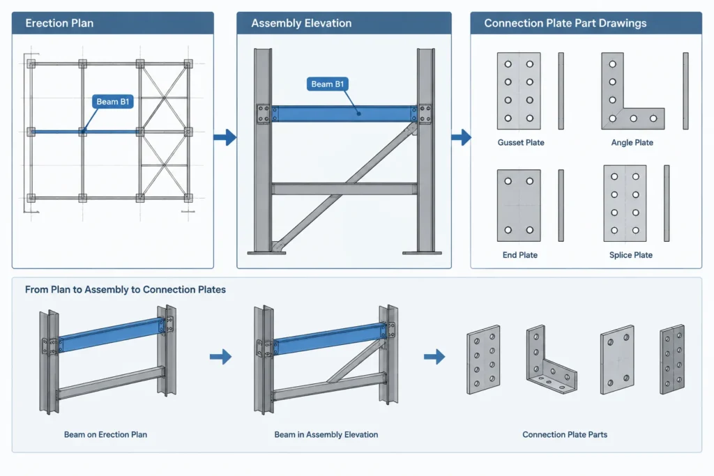
For each assembly, begin at the erection drawing and identify its structural location, mark, direction, elevation, and neighboring members. Then open the assembly drawing and verify that its end conditions and orientation match that location. Finally, trace each attached component to its part definition and confirm that its geometry supports the assembly.
This outside-to-inside review mirrors the real information chain: structure, assembly, component. A second pass from component back to structure can reveal duplicate marks, unintended mirrored parts, or parts assigned to the wrong member.
Clear steel shop drawings do more than display geometry. They establish a controlled path from design intent to individual parts, fabricated assemblies, and final erection. Keeping each drawing focused on its production role makes that path easier to check, revise, and use.