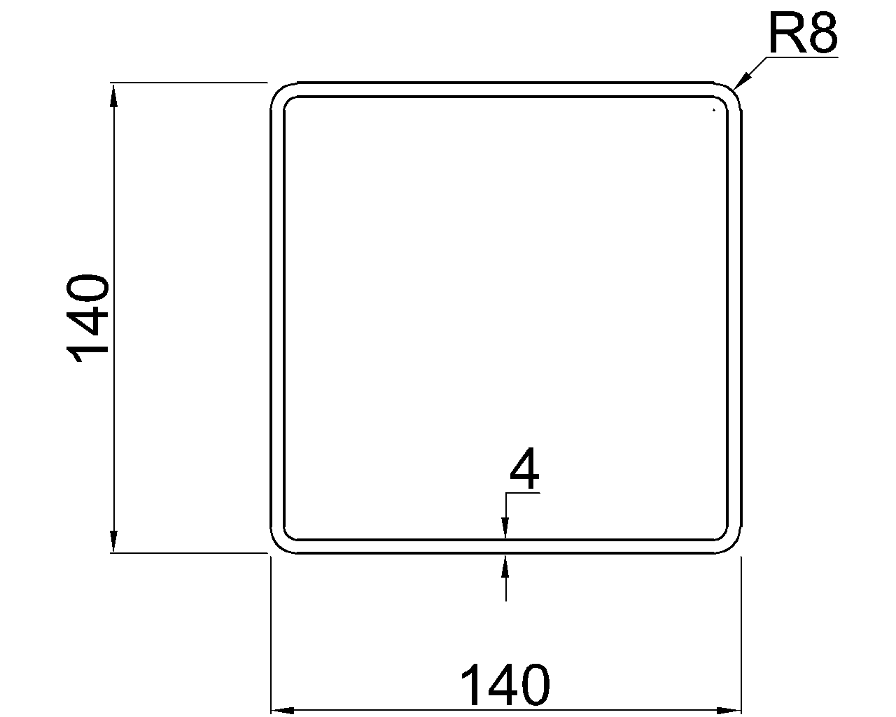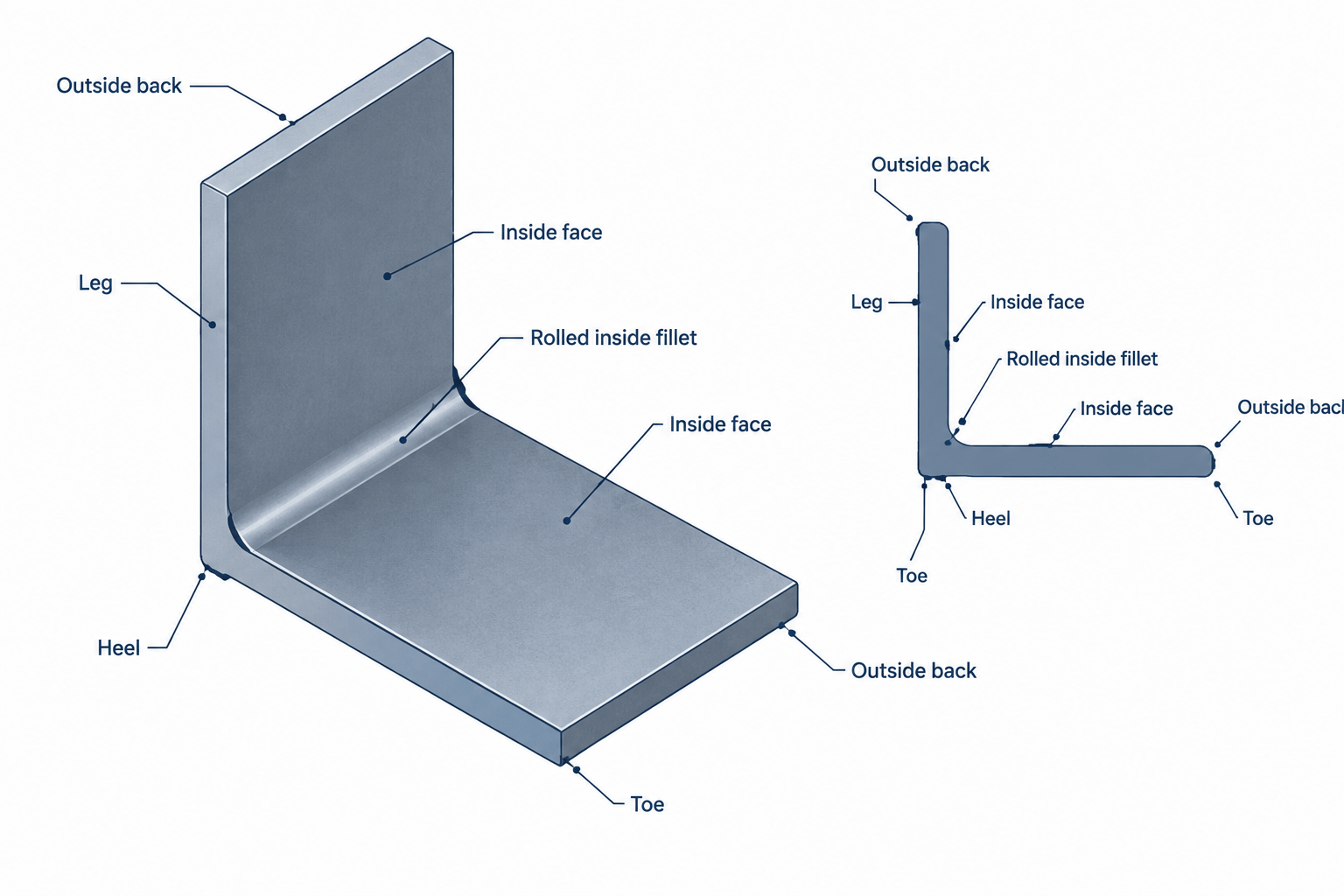
Structural steel angles are simple in appearance but easy to misread in drawings and models. Terms such as heel, toe, back of angle, and outstanding leg identify specific parts or orientations of the section. Using these terms consistently helps prevent mirrored parts, misplaced bolt lines, incorrect offsets, and connection-clearance problems.
This guide explains the anatomy of equal-leg and unequal-leg angles and shows how that terminology applies to section tables, connection details, shop drawings, and CAD geometry. It is an orientation and drafting reference, not a substitute for project drawings, applicable standards, or engineering design checks.
Basic anatomy of a structural angle
A structural angle has two legs arranged approximately perpendicular to each other. The legs meet at an inside corner formed with a rolled fillet rather than a sharp intersection. Each leg extends from that corner to an outer edge called a toe.
| Term | Practical meaning | Why it matters |
|---|---|---|
| Leg | One of the two flat branches of the angle | Leg size and orientation control fit-up and connection space |
| Heel | The outside corner where the backs of the legs meet | Often used as an erection, offset, or placement reference |
| Toe | The free longitudinal edge of a leg | Affects clearance, edge treatment, welding, and interference checks |
| Back of angle | The outside face of either leg | Common face used for contact, dimensioning, and attachment |
| Inside face | The face directed toward the open side of the angle | Contains the rolled inside fillet near the leg intersection |
| Fillet | The curved inside transition between the legs | Limits how closely plates, bolts, and welds can approach the corner |
| Thickness | The listed thickness of the angle leg | Used for section identification and detailing, subject to the governing product data |
Heel and toes: the most important visual references
The heel is the external corner of the L-shaped section. In a simplified line drawing, it may look like the intersection of the two outer leg faces. In the actual rolled product, the opposite inside corner contains a curved fillet.
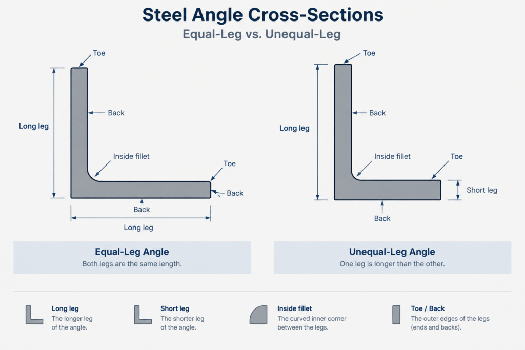
Each angle has two toes, one at the free edge of each leg. Because an unequal-leg angle has legs of different lengths, one toe is farther from the heel than the other. Phrases such as “long leg horizontal” or “short leg outstanding” therefore carry important geometric information.
The heel should not automatically be treated as the centroid or member work line. An angle is not symmetric about axes parallel to its legs, even when both legs have equal nominal length. Its centroid is offset from the backs of the legs, and its principal axes are rotated relative to the leg directions. The correct reference depends on whether the drawing is locating a physical face, a member line, a connection plane, or a calculated section axis.
Back of angle versus inside face
The back of an angle is an exterior flat face of a leg. Since an angle has two legs, it also has two back faces. A note that says only “back of angle” can remain ambiguous unless the view, connection, or orientation makes the intended leg clear.
Back faces are frequently used as dimensional references because they can bear against gusset plates, webs, flanges, masonry, or other connection material. A back-to-back angle assembly places corresponding outside leg faces toward each other, although the actual spacing and connecting components must be established by the detail.
The inside faces point into the open side of the angle. Near the heel, these faces transition through the rolled fillet. A plate corner modeled as perfectly square may interfere with this curved region even when the nominal leg dimensions appear sufficient.
Equal-leg and unequal-leg angles
Equal-leg angles
An equal-leg angle has the same nominal leg length in both directions. This makes section identification easier, but it does not eliminate orientation issues. A connected leg and an outstanding leg can perform different functions, carry different connection patterns, or face different directions in the completed assembly.
Equal nominal legs also do not make the section behave like a doubly symmetric W shape. The open L geometry remains unsymmetric about horizontal and vertical centroidal axes.
Unequal-leg angles
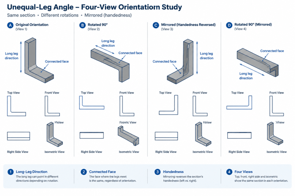
An unequal-leg angle has one long leg and one short leg. The orientation should be communicated explicitly in plans, sections, details, and part drawings. Rotating or mirroring the same section can change:
- which leg contacts the supporting member;
- the available width for bolts or welds;
- the toe location relative to adjacent material;
- the centroid location relative to the connection plane;
- the overall envelope of the assembly; and
- the direction of eccentricity between the member and connection.
Do not rely on the designation alone to communicate installed orientation. Add a clear view, orientation note, or dimension to a physical face.
Connected leg and outstanding leg
The connected leg is the leg attached to another component. The outstanding leg projects away from the connection plane. These are functional descriptions rather than permanent features of a particular angle size.
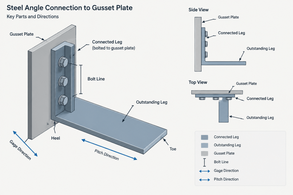
For example, the long leg of an unequal angle may be connected in one detail and outstanding in another. A general rule such as “long leg connected” should not be assumed unless the project documents establish it.
When checking a detail, identify the connected leg before reviewing bolt gages, weld access, cope geometry, or clearances. This simple step catches many mirrored-angle errors.
Rolled fillets and toe geometry
A structural angle should not be represented as two perfect rectangular strips meeting at a sharp inside corner when local fit-up matters. Rolled products include an inside fillet, and the toe regions may also differ from the idealized square edges used in a basic analysis sketch.
The appropriate CAD representation depends on the task:
- Diagrammatic plans and elevations: a simplified outline may be sufficient if it does not create a misleading clearance.
- Connection layouts: account for the fillet when a plate, bolt, washer, weld, or tool approaches the heel.
- Fabrication-sensitive details: use verified shape data and the fabricator’s detailing practices rather than estimating the rolled profile.
- Analysis models: use the correct section properties and member axes; a visually simplified model is not a source of fabrication dimensions.
Never derive an exact fillet radius by scaling a generic symbol or an unverified CAD block. Obtain required geometry from an appropriate published shape reference or project-approved data source.
Bolt gages and dimensions on angle legs
A bolt gage on an angle describes the transverse location of a bolt line on a leg. The reference may be the back of the leg, but the drawing must make the dimension origin clear. Gage should not be confused with pitch, which describes spacing between fasteners along a line.
Available leg width alone does not prove that a bolt arrangement is acceptable. A connection layout may also depend on edge distance, spacing, hole type, fastener installation access, the heel fillet, connected material, and engineering requirements. Use the project connection design and governing criteria rather than creating a pattern from visual fit alone.
For unequal angles, confirm that the gage has been applied to the intended leg. A valid-looking bolt line can be wrong if the part was mirrored or if the long and short legs were exchanged.
How angle orientation appears in drawings
Angle orientation can be communicated through section symbols, visible outlines, hidden lines, callouts, and dimensions. Because an L shape can be rotated into several positions and then mirrored, text-only descriptions are vulnerable to interpretation.
A reliable detail generally establishes at least two references:
- which leg is connected or bears against another component; and
- which direction the outstanding leg points.
Dimensioning to the back or heel is usually clearer than dimensioning to a section centroid that cannot be physically measured in the shop. If a work line or centroidal line is necessary, show its relationship to physical faces with verified section data.
Practical CAD workflow for structural angles
- Confirm the section designation. Check both leg sizes and thickness against the selected shape reference.
- Establish the insertion reference. Decide whether the block or profile is based on the heel, a back face, centroid, or another documented point.
- Set the orientation deliberately. Identify the connected leg, outstanding leg, and direction of the toes before copying or mirroring geometry.
- Separate schematic and fabrication geometry. Do not use a simplified analysis profile as evidence of local fit-up.
- Check the inside corner. Review plates, bolt heads, washers, welds, and neighboring members for conflict with the fillet region.
- Verify annotations after mirroring. Notes such as “long leg vertical” may become incorrect even when the geometry mirrors successfully.
- Coordinate all views. Plans, sections, elevations, and piece details must show the same handedness.
Common angle-detailing mistakes
- Using heel, centroid, and work point as interchangeable references.
- Calling out an unequal angle without showing which leg is vertical or connected.
- Drawing a sharp inside corner and placing another part inside the real fillet region.
- Mirroring a connection without updating leg-orientation notes.
- Measuring a bolt gage from the wrong face.
- Assuming equal-leg angles cannot be installed backward.
- Using the visible CAD outline instead of verified section properties for engineering calculations.
- Assuming that a generic angle block reproduces the exact rolled profile of the specified product.
A useful review sequence
When reading or producing an angle detail, start at the heel and trace both legs to their toes. Identify the long and short legs where applicable, mark the connected leg, and note the direction of the outstanding leg. Then locate bolt lines, welds, plates, and member work lines relative to those physical features.
This vocabulary creates a shared geometric language for designers, drafters, fabricators, and reviewers. Clear steel angle terminology does more than improve notes: it makes orientation, connection layout, and CAD coordination easier to verify before the drawing reaches fabrication.