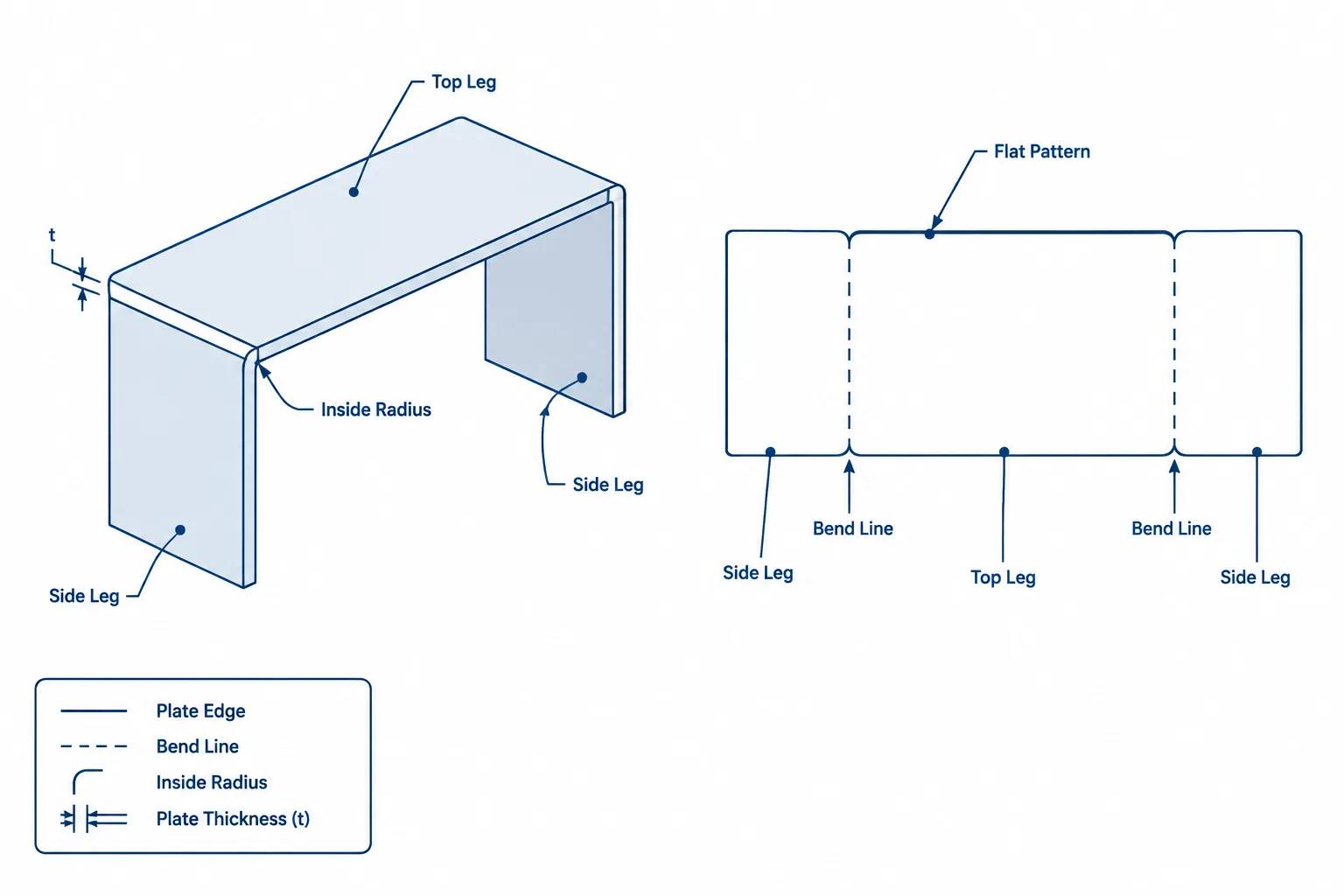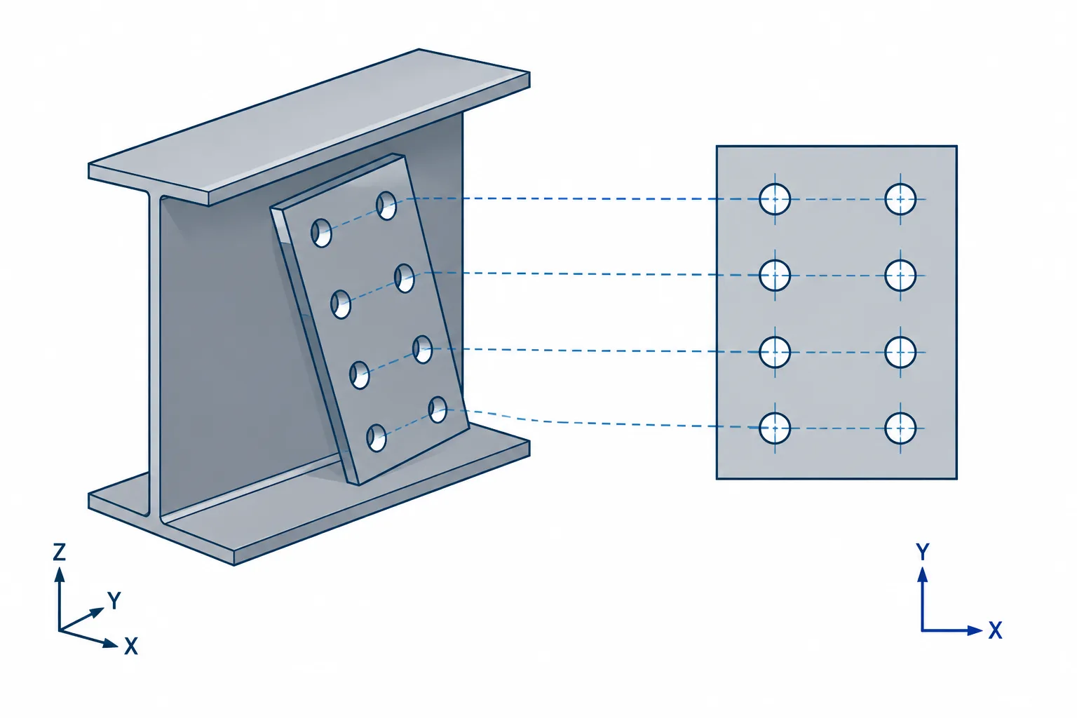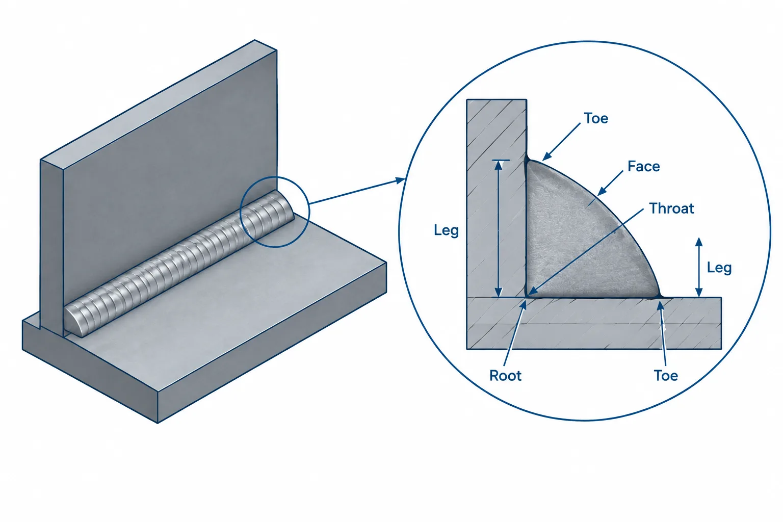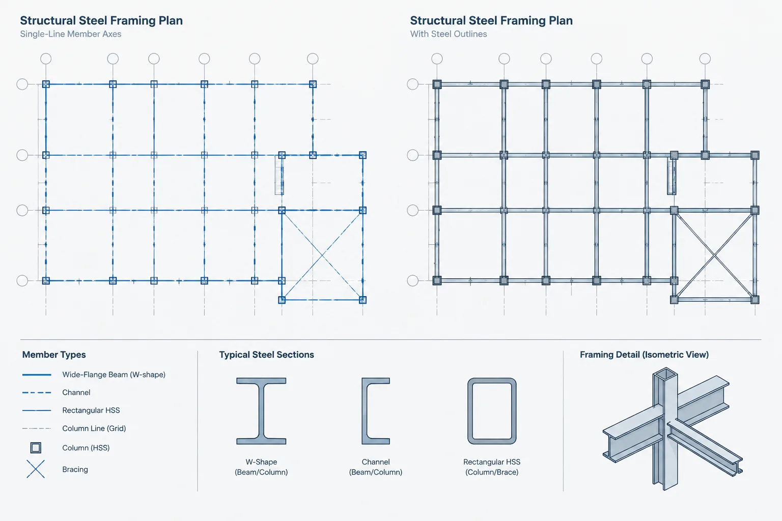
Structural steel members may appear as simple lines in one drawing and as full-width shapes in another. A framing plan might represent a beam with a single line between supports, while a shop detail shows its flanges, web, end cuts, holes, and connection material. Both views can describe the same member, but they serve different purposes.
Understanding single-line vs. double-line structural steel drawings helps prevent a common coordination error: treating a symbolic line as though it were a physical edge. The distinction affects member placement, offsets, clearances, connection geometry, and the way CAD objects should be created and checked.
What Is a Single-Line Steel Representation?
A single-line representation uses one line, polyline, or model axis to indicate a member’s general path. Depending on the drawing convention, that line may represent a work line, member centerline, grid-aligned reference, or another defined layout axis.
The line usually does not show the member’s actual width or depth. A W-shape beam and an HSS member could therefore look similar in plan if both are represented only by their longitudinal axes. Shape designations, member marks, sections, notes, or schedules provide the information that the simplified geometry does not.
Single-line representation is especially useful for:
- Framing plans where the primary objective is member layout.
- Early coordination models and schematic studies.
- Diagrams showing load paths or framing relationships.
- Views drawn at a scale where full section outlines would overlap.
- Centerline-based automation and member scheduling workflows.
A single line is efficient, but its meaning must be defined. It should not automatically be assumed to coincide with the geometric centroid, web centerline, HSS centerline, or face of steel.
What Is a Double-Line Steel Representation?
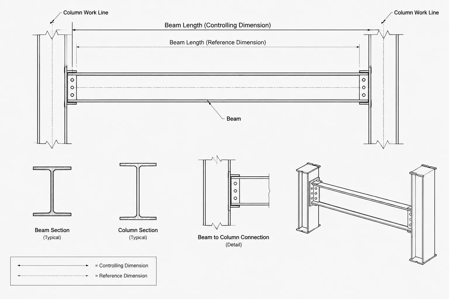
A double-line representation shows visible member boundaries rather than only an abstract axis. In a plan view, a beam may be drawn with two longitudinal lines representing projected flange edges. In an elevation, the top and bottom boundaries may indicate the member depth. More detailed views may also show flange thickness, web thickness, fillets, corner radii, holes, and cuts.
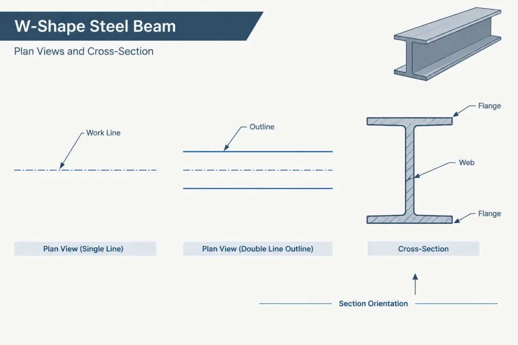
The term double-line is often used informally. The geometry may contain considerably more than two lines, particularly when an actual cross section or fabrication detail is shown. The essential difference is that the drawing communicates physical extents rather than only a member path.
Outline representation becomes important when checking:
- Clearance between adjacent members or building systems.
- Flange interference at crossings and connections.
- Face-of-steel dimensions and offsets.
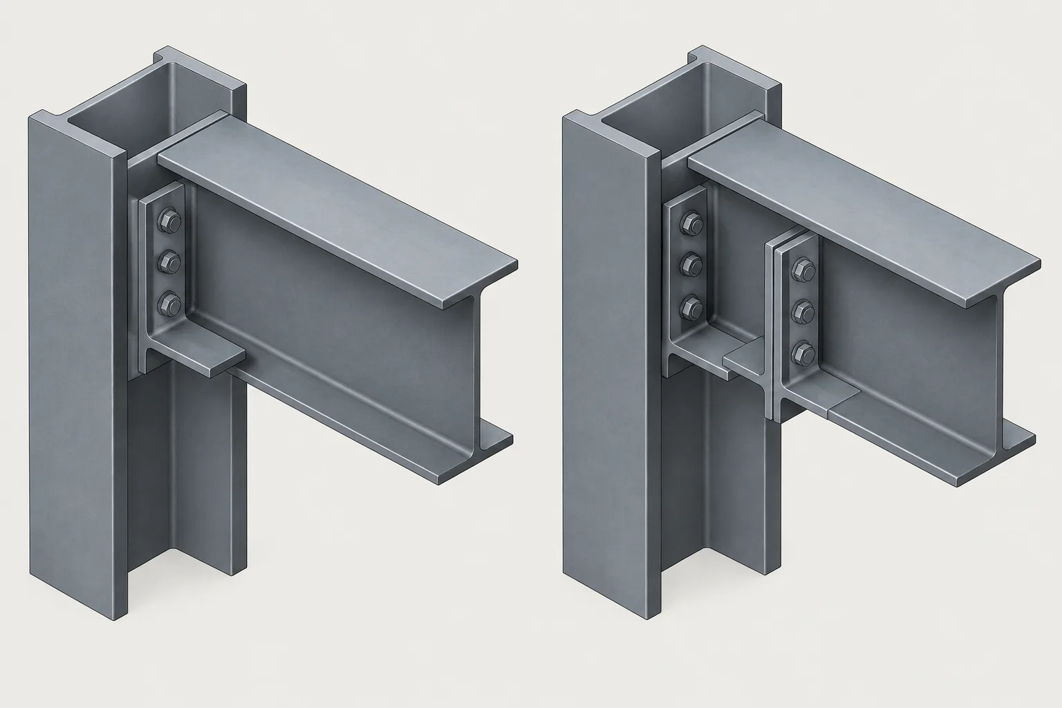
- Connection plate fit and bolt accessibility.
- Copes, notches, skewed ends, and sloped end geometry.
- Actual occupied space in plan, elevation, or section.
What Each Representation Communicates
| Drawing issue | Single-line representation | Double-line or outline representation |
|---|---|---|
| Member path | Communicates it directly | Usually inferred from the outline or an added axis |
| Physical width or depth | Not normally visible | Shown at the drawing’s intended level of detail |
| Section orientation | Requires a symbol, note, section, or model property | May be visible from the projected shape |
| Clearance checking | Limited without section data | Better suited to physical interference checks |
| Drawing congestion | Low | Higher, especially at small scales |
| Fabrication information | Generally insufficient by itself | Can support detailed hole, cut, and attachment information |
| Member scheduling | Efficient when linked to member data | Possible, but raw linework alone may not contain usable data |
Representation by Steel Shape Type
W-Shapes and Other I-Sections
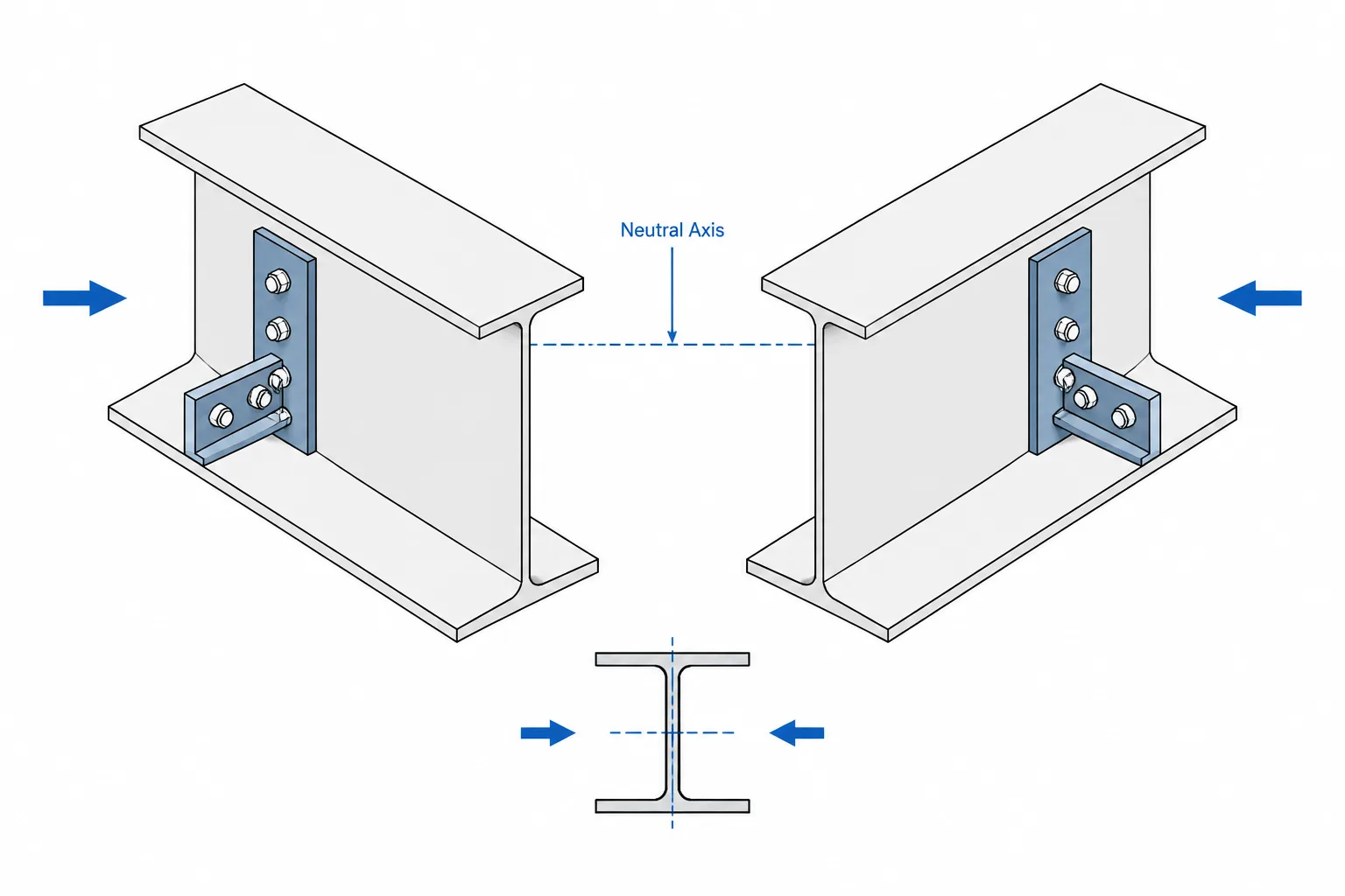
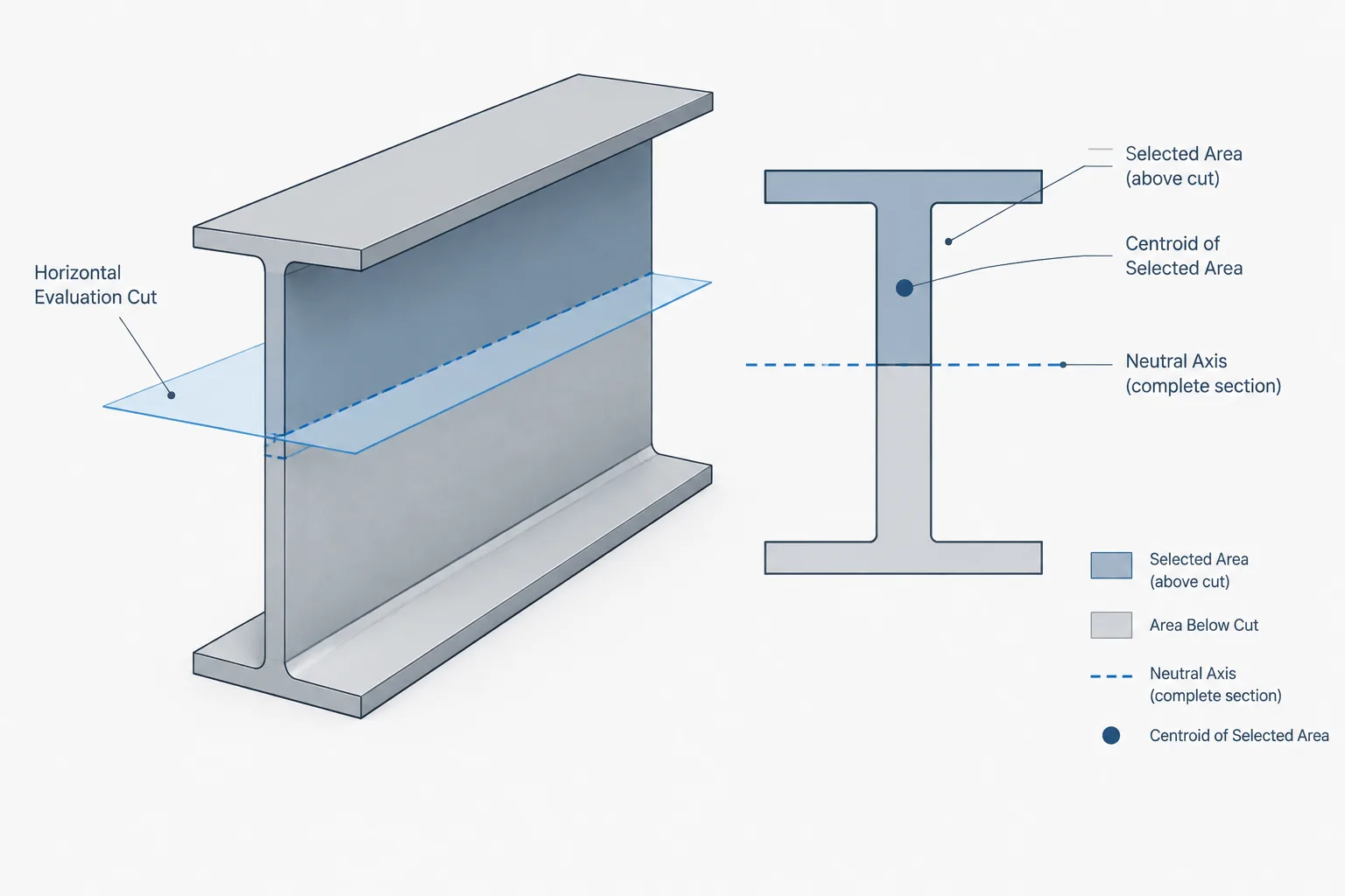
A single line in plan often follows a beam work line or web-related axis, but the drawing convention must confirm this. A full plan outline generally shows the projected flange width. In elevation, the outline indicates overall depth, while a detailed section reveals the flange and web arrangement.
An outline is particularly helpful where flange width affects adjacent framing, façade clearances, deck edges, or connection access. However, a simplified rectangular envelope should not be mistaken for an exact rolled profile.
HSS Members
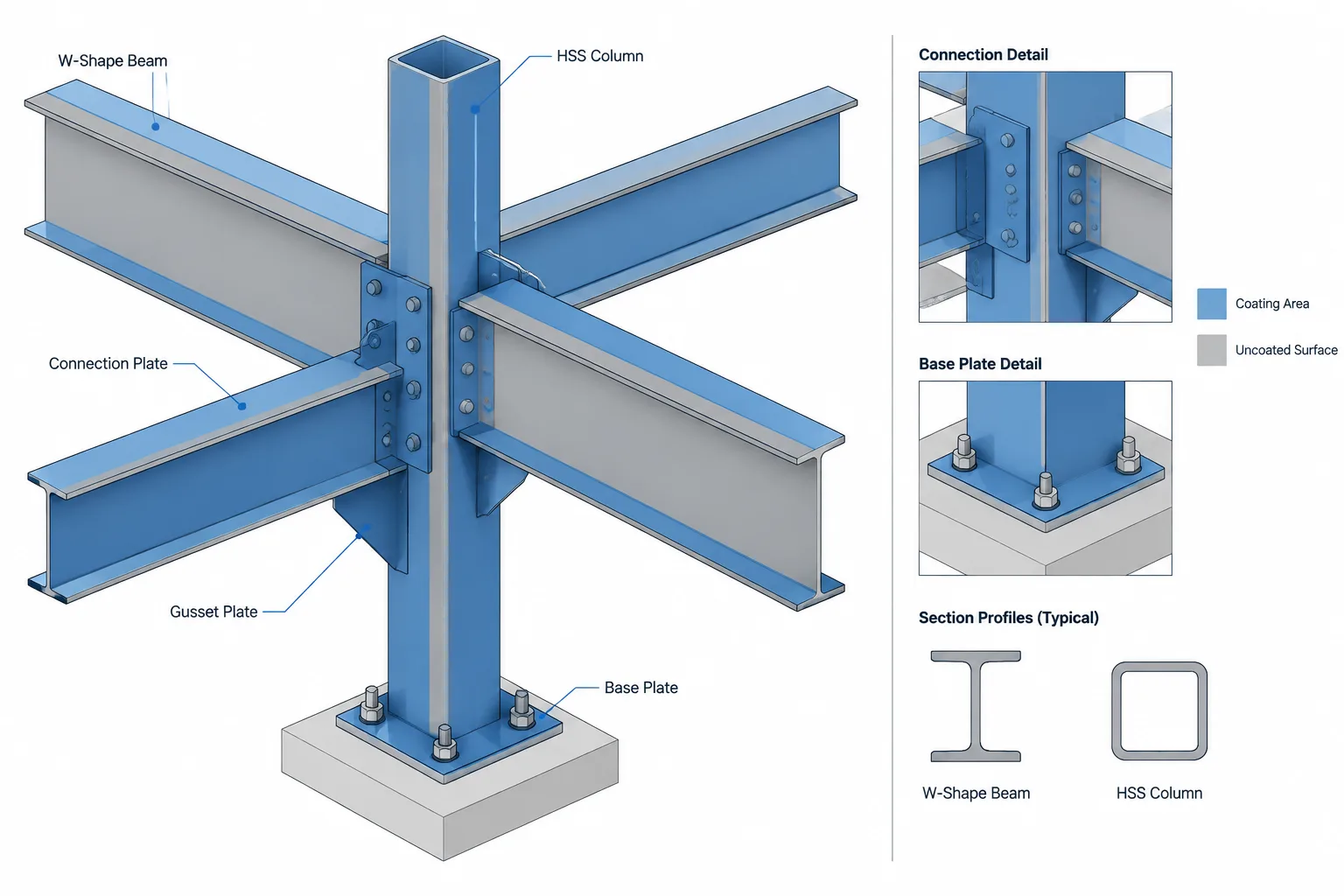
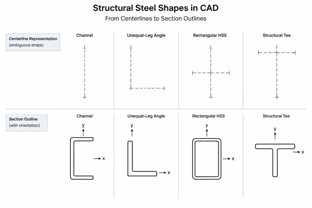
A rectangular or square HSS can be easy to interpret when shown in outline, but its orientation still matters when the side dimensions differ. A single line gives no visual indication of which HSS face is oriented in the drawing plane.
For round HSS, an elevation may show parallel outside boundaries, while an end view shows a circle. Neither view should imply exact wall geometry unless the detail is intended to represent it. Nominal descriptions and actual detailing geometry must remain distinguishable.
Channels and Angles
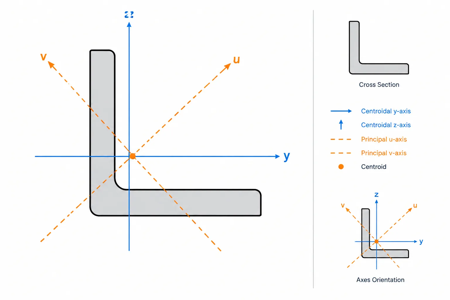
Channels and angles are unsymmetric about at least one relevant axis, so a single member line does not fully communicate orientation. The drawing must establish the channel’s open side or the angle’s leg direction through a section, orientation symbol, note, or unambiguous model view.
Replacing a detailed channel or angle with a centerline without preserving orientation data can reverse connection faces, bolt gages, or outstanding legs.
Structural Tees and HP Shapes
A structural tee requires clear stem-and-flange orientation. An HP shape may look similar to another I-section in a symbolic plan, even though its section proportions and intended use differ. In both cases, the designation and section orientation carry information that a single line cannot provide.
The Most Important Question: What Does the Line Control?
Before dimensioning to a symbolic member line, determine what it represents. Possible references include:
- A member work line connecting theoretical work points.
- The centerline of a web or stem.
- The geometric center of an HSS.
- A grid line on which the member is nominally centered.
- An erection or layout reference offset from the member.
- A modeling axis selected for convenience.
These references can coincide, but they do not always do so. An offset beam, an unequal-leg angle, a channel oriented to one side, or a member with eccentric connection geometry may have several different meaningful lines.
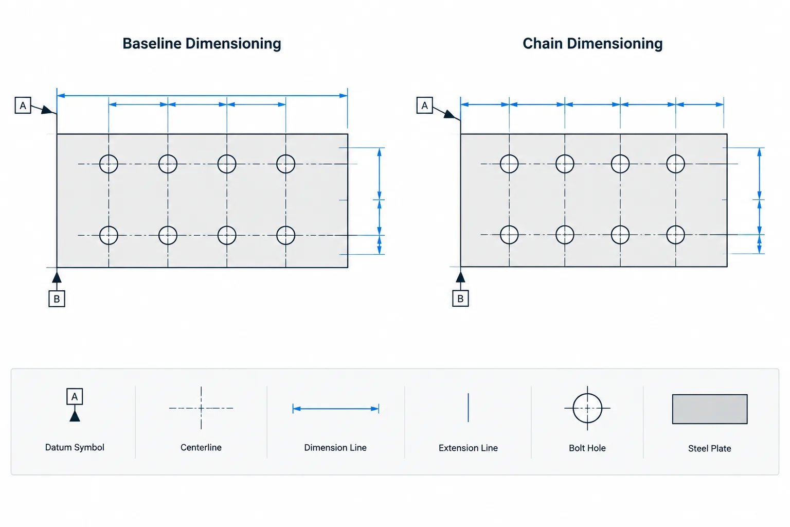
Dimensioning should identify the controlling reference rather than relying on visual proximity. If a physical face controls clearance or fit, dimensioning only to an undefined centerline may leave the required edge location unresolved.
Moving from Framing Plans to Shop Details
The transition from a single-line framing plan to a fabrication-level detail requires more than adding width around the original line. The detailer must confirm the member designation, section orientation, work-point geometry, setbacks, end conditions, and connection interfaces.
A reliable transition generally follows this sequence:
- Identify the intended work line and its relationship to grids or supports.
- Confirm the steel shape and orientation from the governing information.
- Place the section relative to the work line using the intended insertion or justification rule.
- Establish member ends from controlling work points, setbacks, and end planes.
- Add connections, cuts, holes, and attached parts using physical faces and verified geometry.
- Check the resulting outside envelope against nearby steel and coordinated systems.
Simply offsetting both sides of a line by an assumed amount is unreliable. The member may not be centered on the line, and a database outline may include geometry that differs from a simplified drafting envelope.
CAD Workflow: Keep Logical Geometry and Physical Geometry Separate
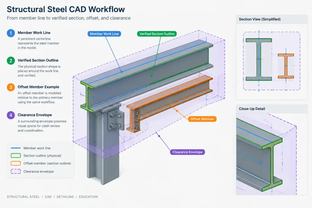
A useful CAD or modeling workflow preserves both the member axis and its physical outline. The axis supports layout, tagging, measurement, and revision control. The outline supports interference review, detailing, and presentation.
Practical layer or object separation can distinguish:
- Work lines and member axes.
- Visible steel outlines.
- Hidden edges.
- Center marks and reference geometry.
- Connection and fabrication geometry.
- Annotation that explains orientation or offsets.
If a member changes size, the physical outline should update from the verified section data while the controlling work line remains stable unless the design intent also changes. This avoids accidental movement of framing references during shape substitutions.
For imported CAD blocks or exploded linework, verify the insertion point and axis convention before snapping other objects to them. A block origin may be located at the centroid, bounding-box center, corner, or another arbitrary point. Its origin is not automatically a project control point.
Common Drawing and Coordination Errors
- Using lineweight as member width: A plotted symbolic line has no reliable relationship to the steel’s physical size.
- Assuming every beam is centered on a grid: Framing can be intentionally offset for alignment, clearance, or connection reasons.
- Losing section orientation: Simplifying channels, angles, tees, or rectangular HSS to lines can remove essential directional information.
- Checking clashes with centerlines only: Intersecting axes do not reveal flange, plate, bolt, or access conflicts.
- Dimensioning to a graphic edge at small scale: A schematic outline may be displaced or exaggerated for readability.
- Exploding intelligent members too early: Unrelated linework can become inconsistent when the section size or orientation changes.
- Using a bounding rectangle as an exact section: Envelopes are useful for clearance checks but may omit recesses, fillets, tapers, and wall geometry.
Review Checklist
- Is the view symbolic, diagrammatic, or intended to show physical steel extents?
- Is the meaning of the member line defined?
- Can the steel shape and orientation be identified without guessing?
- Are dimensions tied to controlling references rather than convenient graphics?
- Does the outline come from verified shape information?
- Have offsets between work lines, centerlines, and faces of steel been preserved?
- Were clearance checks performed using physical envelopes rather than only axes?
- Will a section-size revision update the outline without unintentionally moving the work line?
Use the Simplest Representation That Preserves Intent
Single-line structural steel drawings are efficient for layout and communication at broader scales. Double-line and full-outline views are necessary when physical dimensions, orientation, fit, and fabrication geometry matter. Neither method is universally better; each communicates a different level of information.
The safest workflow treats the work line as logical geometry and the steel outline as physical geometry. Keeping that distinction clear allows framing plans, models, shop details, and CAD resources to remain coordinated without mistaking a drafting symbol for an actual edge of steel.