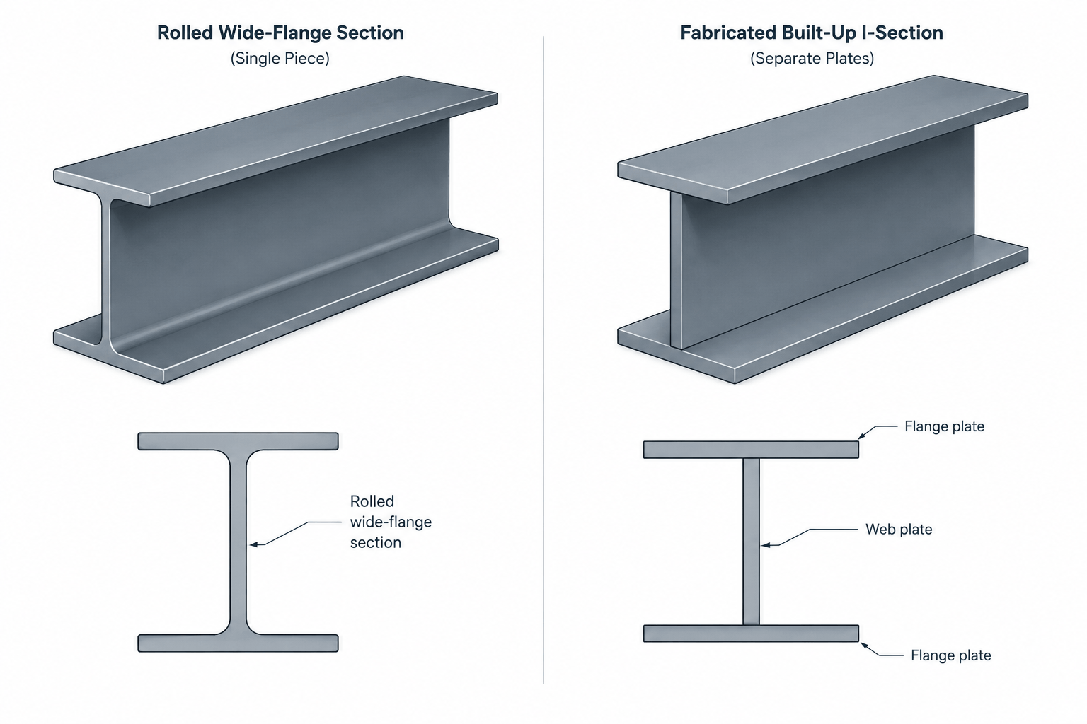
A rolled W-shape, a welded plate girder, and a pair of channels connected with plates may perform similar structural roles, but they are not interchangeable drawing objects. Each is defined differently, modeled differently, and documented with a different level of fabrication information.
Recognizing rolled shapes versus built-up steel members is important when reading structural drawings, preparing shop details, creating CAD geometry, or extracting material quantities. The distinction also determines whether section properties can be taken directly from a published shape table or must be calculated for a project-specific assembly.
What is a rolled structural shape?
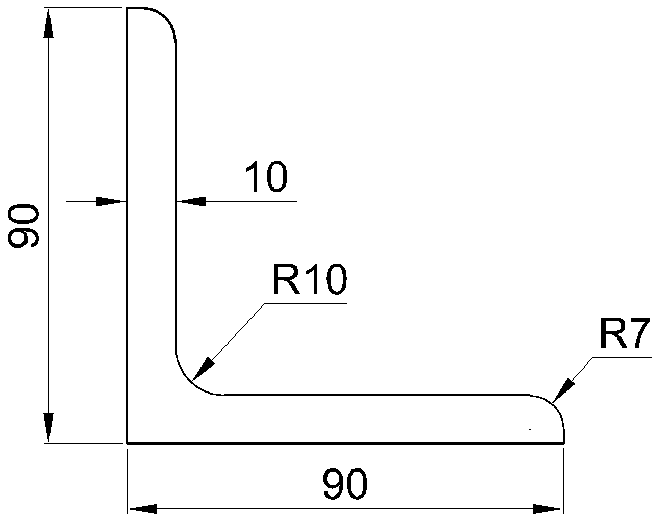
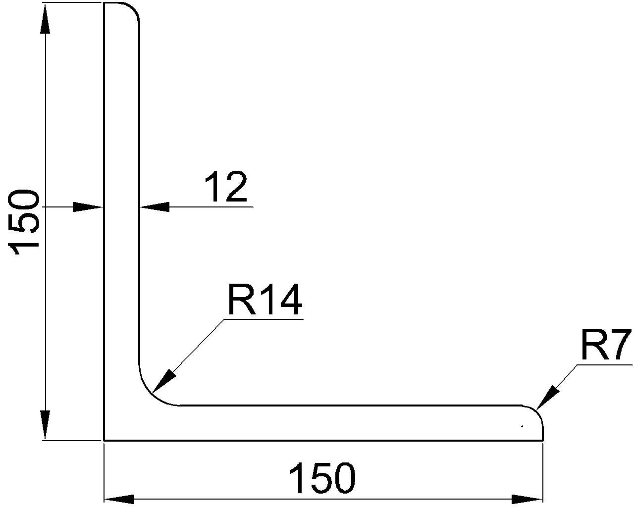
A rolled structural shape is formed at a steel mill into a standardized cross-section. Common examples include W-shapes, channels, angles, structural tees, and certain pile shapes. The designation identifies a recognized shape series and size, allowing users to look up dimensions, weight per unit length, area, moments of inertia, section moduli, and other published properties.
For drafting purposes, the designation is usually the primary geometric reference. Once the exact shape has been confirmed, a verified shape database can provide the nominal depth, flange width, web and flange thicknesses, fillet-related dimensions, and section properties needed for the drawing or model.
Rolled shapes are not assembled from ideal rectangular plates. Their profiles include transitions, fillets, tapers, or other production geometry associated with the shape type. A simplified CAD outline may be appropriate for some general arrangement drawings, but connection fit and fabrication work can require more complete geometry.
What is a built-up steel member?
A built-up member is created by joining multiple steel elements so they act as one member or assembly. Its components may include plates, rolled shapes, bars, or combinations of those products. Welding is common, but bolts and other connection arrangements may also be used where shown by the project design.
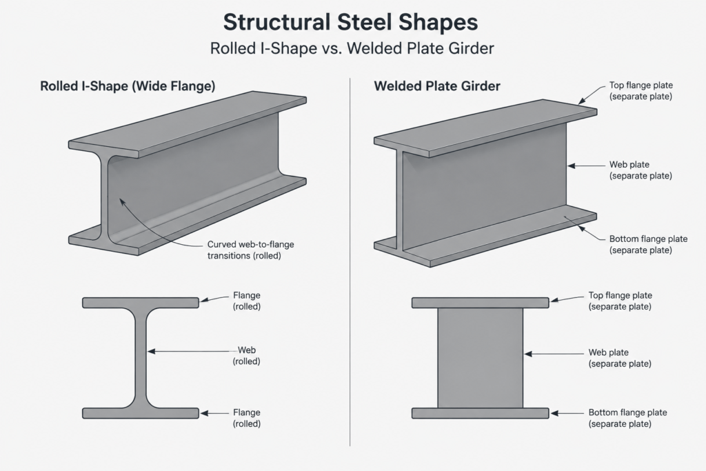
Typical built-up configurations include:
- Plate girders assembled from separate flange and web plates
- Box-shaped members fabricated from plates
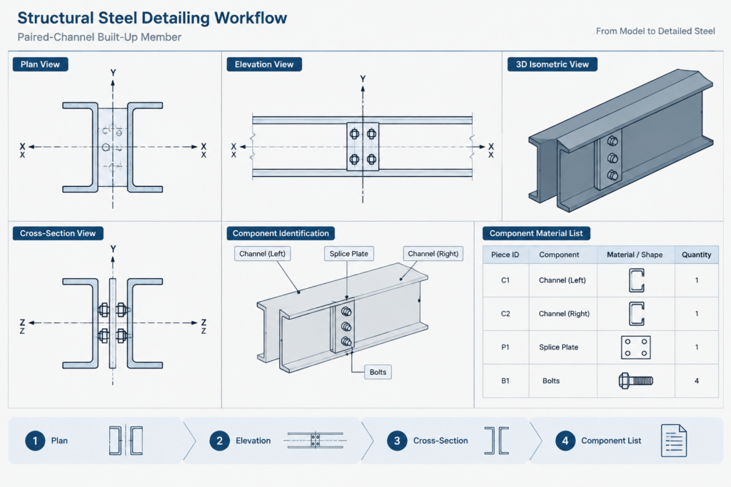
- Two channels connected back-to-back or toe-to-toe
- Double-angle members with connectors or intermediate plates
- W-shapes reinforced with flange cover plates or web doubler plates
- Columns assembled from several rolled shapes and connecting elements
A built-up member is defined by its component geometry and connection details rather than by a single standard rolled-shape designation. Even when its cross-section resembles a familiar I-shape or box section, its dimensions and properties are project-specific unless the documents identify a recognized manufactured product.
Do not identify a section by appearance alone
In an elevation, a welded plate girder can look much like a W-shape. In a small-scale section, a fabricated box can resemble HSS. This visual similarity is not enough to establish the member type.
Look for evidence in the member callout, schedules, section details, weld information, plate labels, and bill of materials. A W-shape designation points to a published rolled section. A callout listing separate flange and web plates indicates fabrication from components. References to cover plates, lacing, battens, stitch welds, or connector plates also suggest a built-up member or a reinforced rolled shape.
If a drawing provides only an ambiguous outline, do not assign a standard section based on approximate proportions. Request clarification before using database properties, generating fabrication geometry, or ordering material.
Key differences for drawings and models
| Issue | Rolled shape | Built-up member |
|---|---|---|
| Primary definition | Standard shape designation | Component sizes, arrangement, and connections |
| Section dimensions | Obtained from a verified shape reference | Taken from project drawings and details |
| Section properties | Published for the identified shape | Calculated for the assembled section as required |
| Cross-section geometry | Includes rolled profile features | Depends on plate edges, welds, gaps, and component placement |
| Material takeoff | Often begins with member length and listed unit weight | Requires separate accounting for components and connection material |
| Fabrication documentation | Focuses on cuts, holes, attachments, and end preparation | Also defines assembly layout, welds, component orientation, and sequencing information |
Section properties require special care
Published properties for a rolled shape apply to that shape in its documented configuration. They should not be reused for a built-up section merely because the two outlines appear similar.
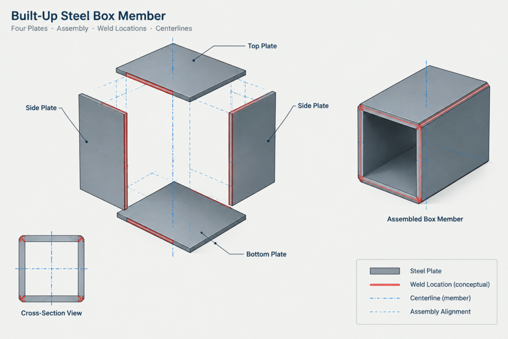
For a built-up member, the centroid and principal axes depend on the size and location of every effective component. Moments of inertia can be developed from the component properties and the parallel-axis relationship, while torsional and warping behavior may require more specialized analysis. Open built-up sections can behave very differently from closed boxes, even when their overall depth and width are similar.
Connection details also matter. Components cannot automatically be assumed to act as a fully composite section under every loading condition. The structural design must establish the intended force transfer and the required welds, bolts, diaphragms, connectors, or intermediate attachments. A drafter should document that design rather than infer composite action from geometry alone.
Modeling rolled and built-up members in CAD
Rolled-shape workflow
Start with the exact designation shown in the contract or approved detailing information. Insert or create geometry from a verified shape source, then confirm the insertion point, member axis, rotation, and level. Keep simplified and fabrication-level representations distinct so a schematic outline is not mistaken for an accurate profile.
Built-up member workflow
Model the individual plates and shapes when their interfaces affect dimensions, weld locations, hole placement, clearances, or quantities. Establish a consistent reference system, such as the member work line, web centerline, outside face, or another explicitly identified datum.
A single combined outline may be useful for general arrangement work, but it can hide important information. Separate components make it easier to detect interference, assign piece marks, produce material lists, and revise one plate without redrawing the entire section.
Use descriptive object names
CAD layers, blocks, or model objects should distinguish the main member from reinforcement and attachments. Generic names such as “beam” or “plate” provide little help during checking. Descriptions tied to the member mark and component function make revisions and quantity review more reliable.
Dimensioning a built-up section
A useful built-up member detail defines the assembly rather than only its overall envelope. Depending on the design and fabrication method, the drawing may need to establish:
- Overall depth and width
- Individual plate widths and thicknesses
- Web location relative to the flanges or reference axis
- Spacing and orientation of paired rolled shapes
- Extent and termination of cover or reinforcement plates
- Component end offsets and transitions
- Hole patterns and attachment locations
- Weld symbols, limits, and references supplied by the design documents
Avoid creating closed dimension chains that can conflict after revision. Select stable datums and use them consistently across section views, elevations, and component details. When symmetry is intended, state or dimension it clearly rather than relying on the apparent balance of the drawing.
Material takeoff differences
For a plain rolled member, an initial steel weight estimate is commonly based on its documented unit weight and cut length. Separate material must still be included for plates, stiffeners, connection angles, bolts, weld-related allowances where applicable to the estimating method, and other attachments.
A built-up member requires component-level takeoff. Web plates, flange plates, rolled-shape components, diaphragms, stiffeners, lacing, splice material, and attachments should be identified separately. The sum of theoretical component weights is not automatically the same as purchased, fabricated, or shipped weight because procurement sizes, cutting plans, waste, and project estimating conventions vary.
Practical checking sequence
- Read the complete member callout and nearby notes.
- Determine whether the designation identifies a standardized shape or a fabricated assembly.
- Locate all referenced sections, schedules, and typical details.
- Confirm the member work line and cross-section orientation.
- For rolled shapes, verify the exact database entry before using dimensions or properties.
- For built-up members, list every component needed to define the section.
- Check whether reinforcement changes along the member length.
- Compare plan, elevation, section, and material-list information for consistency.
- Flag missing geometry or connection requirements instead of assuming them.
Use the right reference for the member type
Shape databases are efficient references for standardized rolled sections. They are not substitutes for project-specific details of welded plate girders, fabricated boxes, paired-shape assemblies, or reinforced members. Conversely, a rolled shape should not be redrawn as an approximate collection of rectangles when accurate profile dimensions are needed.
The safest workflow is to classify the member first, establish the controlling source of geometry, and then choose the appropriate drafting and checking method. That simple distinction prevents incorrect section properties, incomplete material takeoffs, and CAD models that look plausible but do not represent the specified steel assembly.