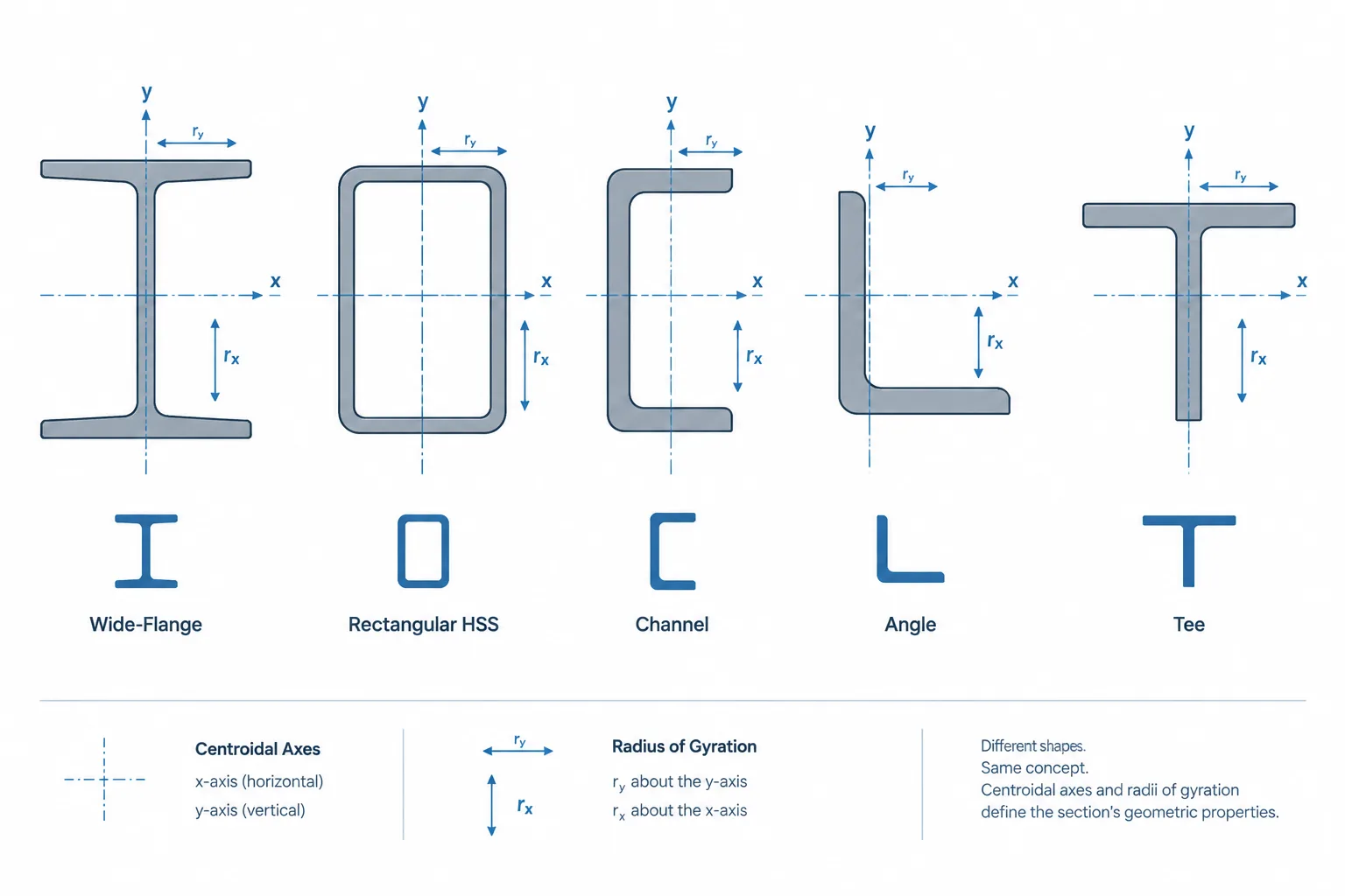
Radius of gyration is a section property commonly listed for W-shapes, channels, angles, tees, HSS, and other structural steel profiles. It is especially important when evaluating members that may buckle in compression. Despite its name, radius of gyration is not a physical radius that can be measured directly on the shape. It is a calculated measure of how the cross-sectional area is distributed about an axis.
Shape tables often report values such as rx and ry. Using the correct value requires more than selecting the smaller number. The user must identify the relevant section axis, understand the member’s restraint conditions, and confirm that the table axes match the axes used in the model or calculation.
What Radius of Gyration Represents
The radius of gyration of an area about a given axis is defined by:
r = √(I/A)
where:
- r is the radius of gyration about the selected axis,
- I is the area moment of inertia about that axis, and
- A is the cross-sectional area.
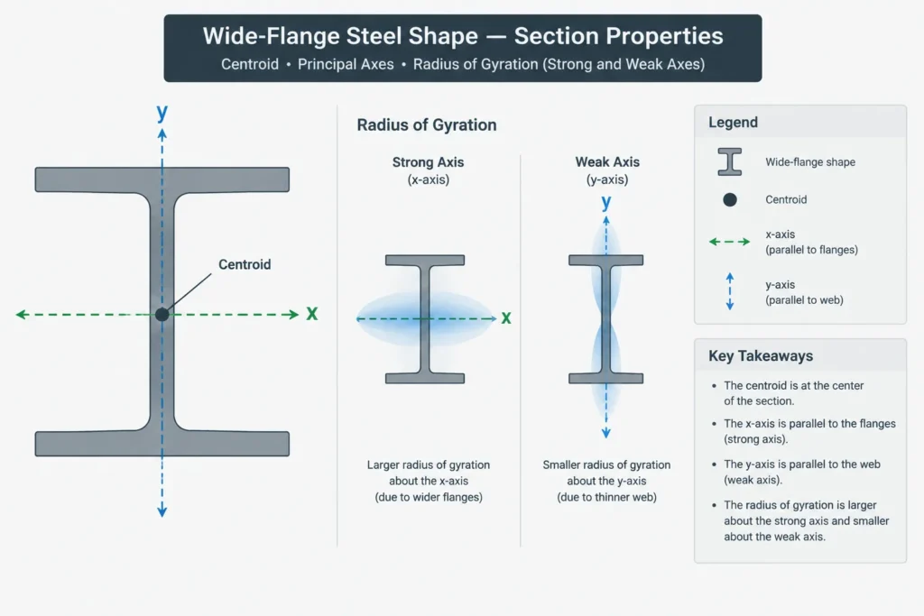
This relationship combines section area and area distribution into one length-based property. If more of the section’s area lies farther from an axis, the moment of inertia and radius of gyration about that axis tend to increase. If the area is concentrated close to the axis, both tend to decrease.
One useful interpretation is that r describes an equivalent distance at which the entire area could be imagined as concentrated while retaining the same moment of inertia. This is a mathematical interpretation, not a description of the actual profile geometry.
Why the Units of r Are Units of Length
Area moment of inertia has units of length to the fourth power, while area has units of length squared. Dividing I by A produces length squared, and taking the square root produces length. Radius of gyration may therefore be listed in inches in an imperial table or millimeters in a metric table.
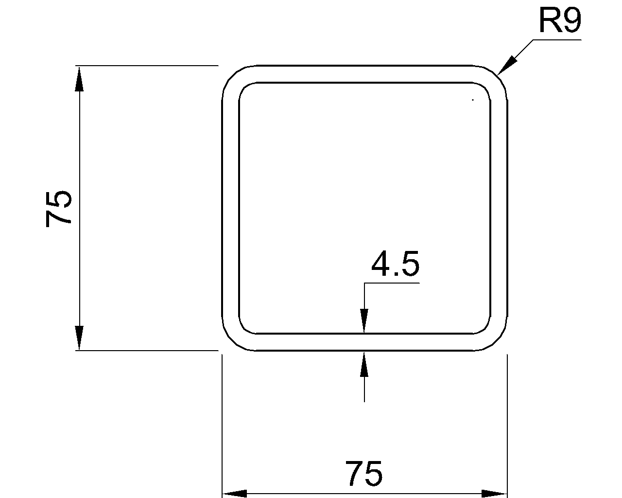
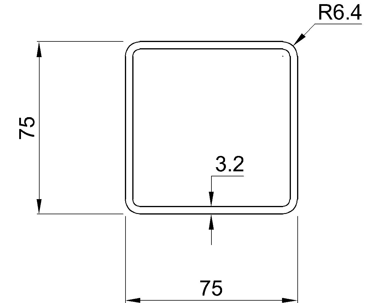
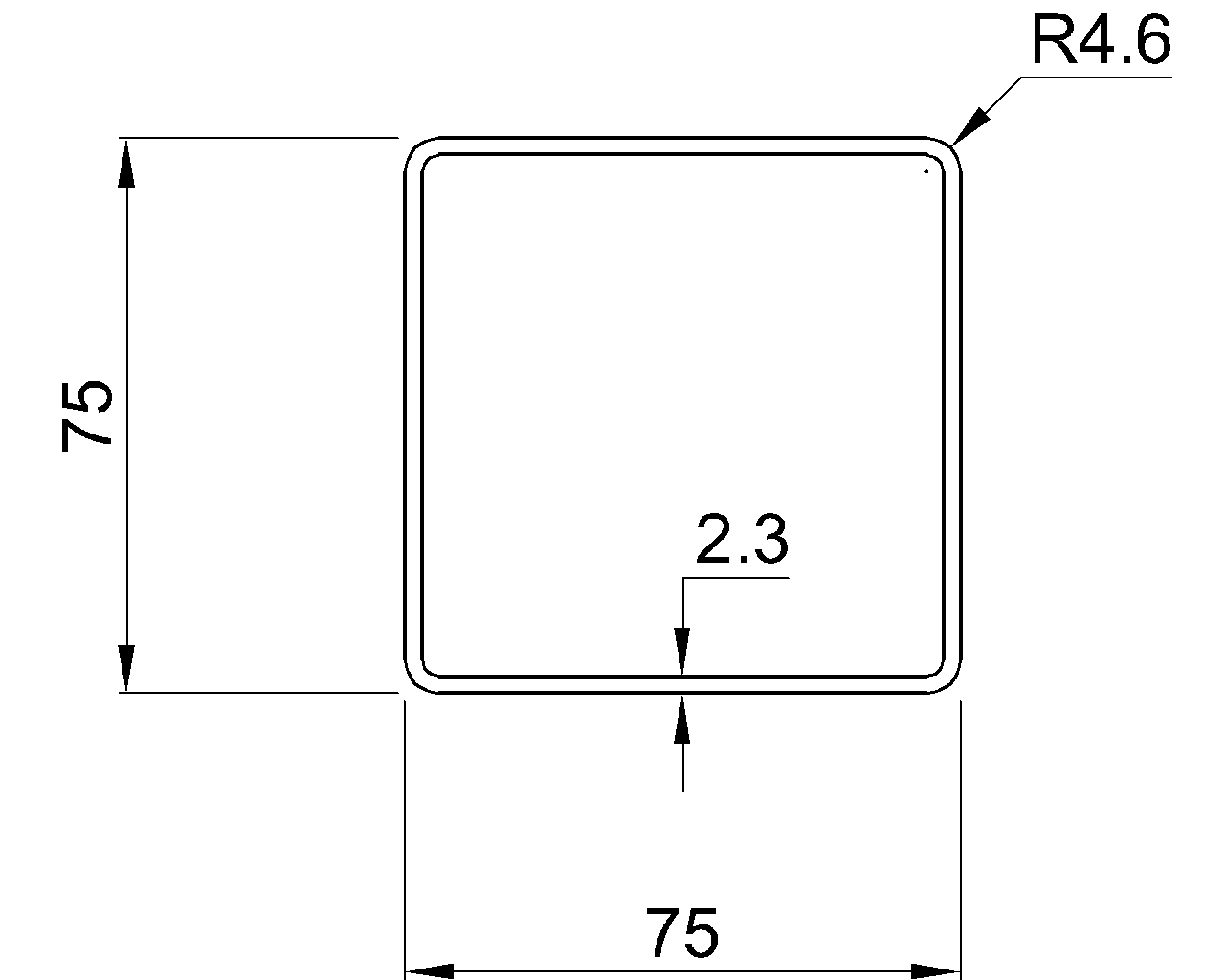
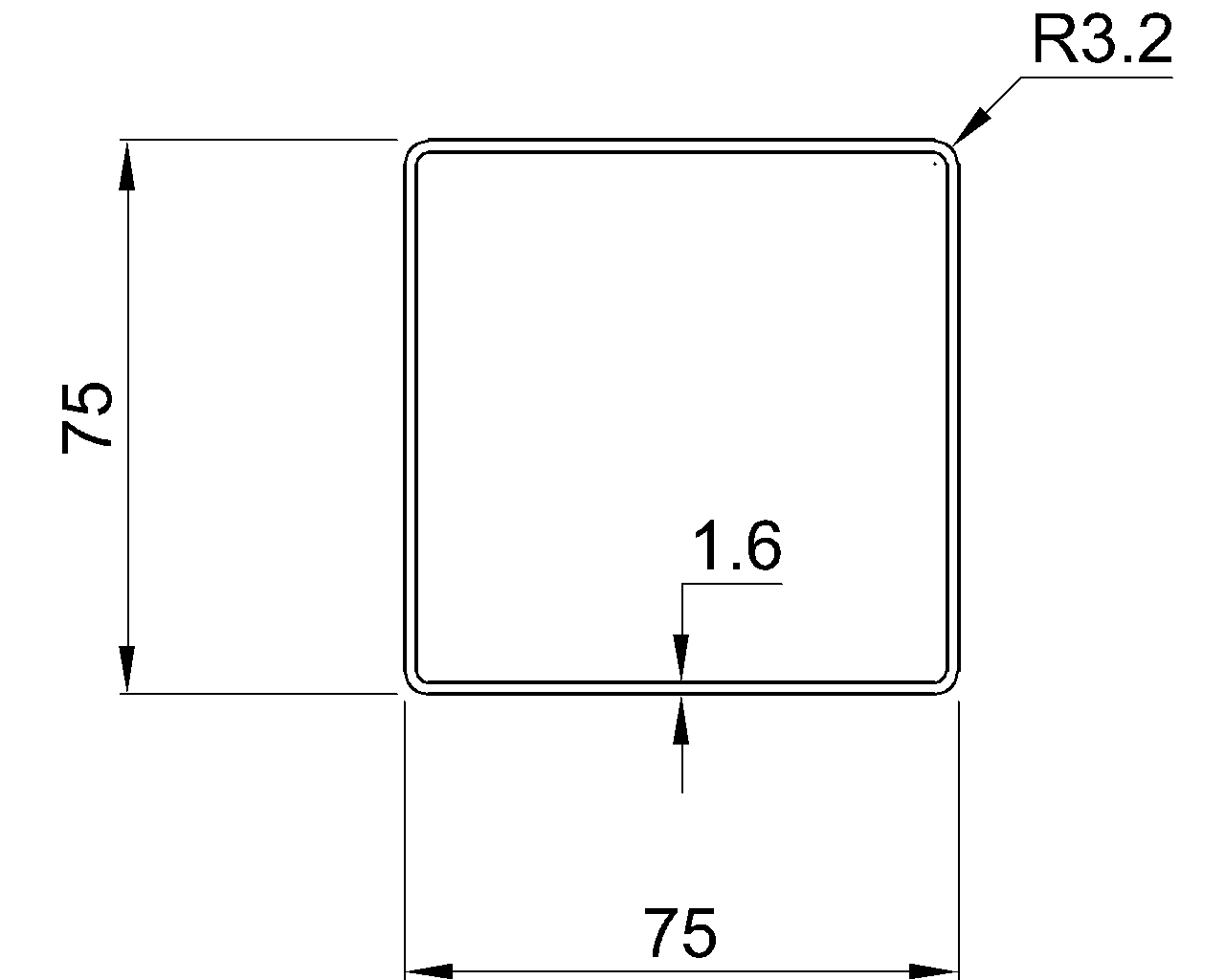
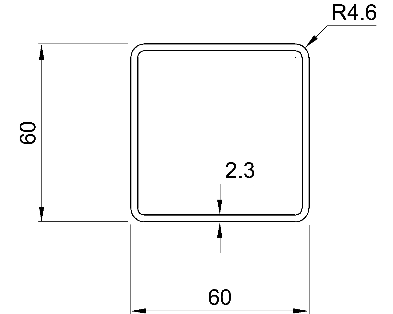
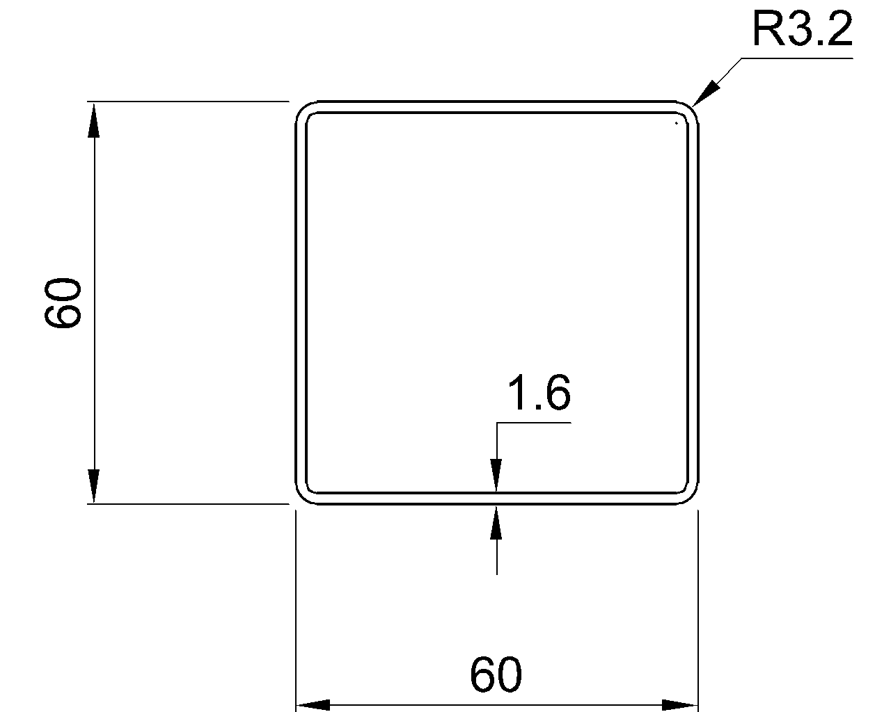
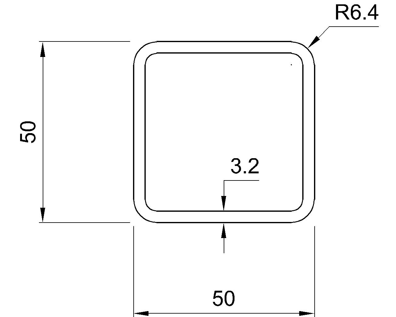
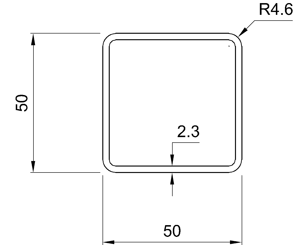
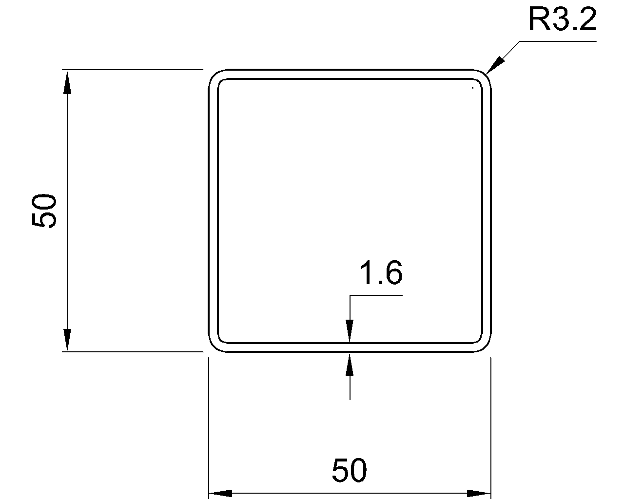
This dimensional check is useful when importing shape data. A column labeled r should not contain values expressed as area or length to the fourth power. It also should not be confused with a corner radius, fillet radius, HSS outside corner radius, or bend radius.
Understanding rx and ry
Subscripts identify the axis about which the property is calculated:
| Property | Meaning | Related table value |
|---|---|---|
| rx | Radius of gyration about the section x-axis | Ix |
| ry | Radius of gyration about the section y-axis | Iy |
| ru, rv, or similar notation | Radius of gyration about principal axes used for some unsymmetric sections | Principal moments of inertia |
For a typical W-shape shown in its usual orientation, the x-axis passes through the centroid parallel to the flanges, while the y-axis passes through the centroid parallel to the web. The wide flange distribution usually gives the shape a larger radius of gyration about the x-axis than about the y-axis. The y-axis is consequently important in many weak-axis buckling evaluations.
That familiar relationship should not become an automatic assumption for every profile. A rectangular HSS can be rotated, a tee can be oriented stem-up or stem-down, and a built-up member can have axes that differ from those of its individual components. Always use the axis definitions shown by the applicable shape reference.
Radius of Gyration and Member Slenderness
For compression-member work, radius of gyration appears in the slenderness expression:
KL/r
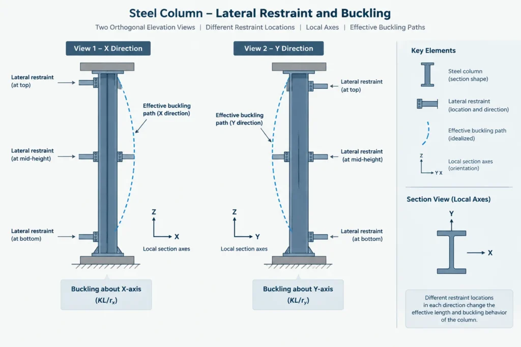
Here, L is a relevant member length and K represents an effective-length factor for the buckling condition being considered. Radius of gyration supplies the cross-sectional part of the relationship. A smaller r, with the other terms unchanged, produces a larger slenderness value.
The axis used for r must correspond to the potential buckling direction and its associated effective length. It is not generally sufficient to calculate one KL/r value using the overall member length and the smallest tabulated radius. Restraints may differ by direction, so the relevant effective lengths may also differ.
For example, intermediate framing might restrain movement associated with one section axis while leaving the other direction less frequently braced. A larger radius of gyration does not automatically govern, and neither does the longer physical dimension of the cross section. The comparison must pair each radius with the correct member-axis restraint condition.
Do Not Confuse r with Other Section Distances
Radius of gyration is related to area and moment of inertia, but it is not interchangeable with other dimensional or section-property terms:
- Depth or width: Physical overall dimensions of the profile.
- Extreme-fiber distance: The distance from a neutral axis to an outer edge, used when relating moment of inertia to elastic section modulus.
- Fillet or corner radius: A physical geometric feature of a rolled or formed section.
- Polar radius: A term that may arise in other mechanics contexts and should not be substituted for an axis-specific section radius without confirming the definition.
- Radius of gyration of mass: A mass-dynamics property, distinct from the area property used in structural shape tables.
Unsymmetric Sections and Principal Axes
Single angles require particular care. Their conventional x and y axes may not be principal axes, and principal-axis properties may be provided using rotated axes. The minimum principal radius can be relevant to member behavior, but the proper analysis depends on loading, end conditions, connection eccentricity, and applicable design provisions.
A structural tee is symmetric about one centroidal axis but not the perpendicular axis. Its centroid is displaced toward the flange, yet its two centroidal symmetry-related axes can still be used for the listed section properties. Channels also have a centroid offset from the back of the web, so placing the CAD insertion point at the web face rather than at the centroid can create an axis-location error even when the shape is drawn correctly.
For asymmetric built-up sections, principal axes may need to be calculated from the complete assembly. Simply taking the smallest radius from an individual angle, channel, or tee does not provide the radius of gyration of the combined member.
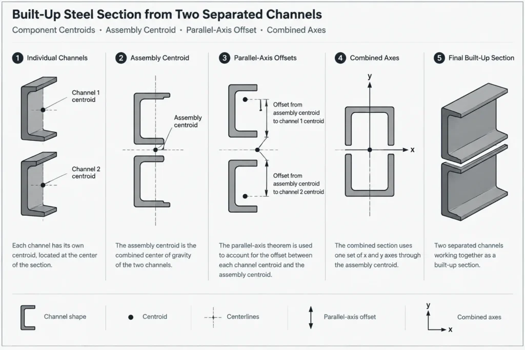
Calculating r for a Built-Up Steel Section
For a built-up section, first establish the centroid of the complete cross section. Then calculate the moment of inertia of every component about the selected assembly axis, including parallel-axis terms where required. Add the component areas and moments of inertia, and finally use r = √(I/A).
Common mistakes include:
- Averaging the radii of gyration of the component shapes.
- Adding individual radii directly.
- Using each component’s own centroidal inertia without transferring it to the assembly axis.
- Ignoring plates, spacers, or other elements that are intended to act as part of the cross section.
- Assuming separated components act as one section without verifying the connecting system and structural behavior.
The section-property calculation and the question of whether the parts act together are separate issues. CAD geometry can calculate properties for a closed composite outline, but it cannot by itself establish composite structural action.
A Practical Shape-Table and CAD Workflow
- Confirm the exact shape designation. Similar-looking profiles can have different area, inertia, and radius values.
- Read the table’s axis diagram. Do not infer x and y solely from the current screen orientation.
- Check the units. Keep section properties and member lengths in a consistent unit system before calculating slenderness.
- Map local axes. Confirm how the analytical model, BIM object, or CAD block assigns local member axes.
- Account for rotation. A section rotated in the model retains its section properties, but the relationship between local and global directions changes.
- Pair each r with the appropriate length and restraint condition. Evaluate the applicable directions separately.
- Verify unusual sections independently. Built-up, modified, coped, perforated, or reinforced members may not match a standard gross-section table entry.
What Changes Radius of Gyration?
Because r depends on both I and A, a shape modification can affect it in a way that is not obvious from area alone. Adding material far from an axis can increase inertia efficiently, while adding the same area near that axis may have a smaller effect. Removing material also changes both terms in the equation.
This is why a heavier shape does not necessarily provide a proportionally larger radius of gyration in every direction. Shapes within the same nominal depth series may distribute added area differently among the web and flanges. Compare the published properties rather than estimating r from weight or overall depth.
Key Takeaway
Radius of gyration is a compact measure of area distribution about a specified section axis. Read it together with the associated moment of inertia, axis diagram, units, member orientation, and restraint conditions. For standard shapes, verified shape tables are the appropriate starting point. For modified or built-up members, calculate the properties of the actual effective cross section and confirm that the analytical axes match the drawing and model axes.