Structural angles look simple in plan and section, but their section-property behavior is less intuitive than that of doubly symmetric W shapes or rectangular HSS. The centroid of an angle is not located at the intersection of its leg centerlines, and its principal axes generally do not align with the legs. This matters when reading shape tables, evaluating bending, orienting a structural model, or preparing a CAD section.
The principal axes of steel angles are centroidal directions for which the product of inertia is zero. Bending behavior is uncoupled about these directions, so they provide a natural reference for understanding an angle’s maximum and minimum centroidal moments of inertia. Shape-table notation varies, however, and principal axes may be identified with labels such as u-v, z-w, or another convention. Always follow the axis diagram supplied with the property source.
Why an angle needs more than ordinary x-y axes
For many steel sections, the most familiar centroidal axes are horizontal and vertical. On a W shape, these directions also coincide with symmetry axes and principal axes. A single angle is different because its material is distributed unevenly around centroidal axes drawn parallel to the legs.
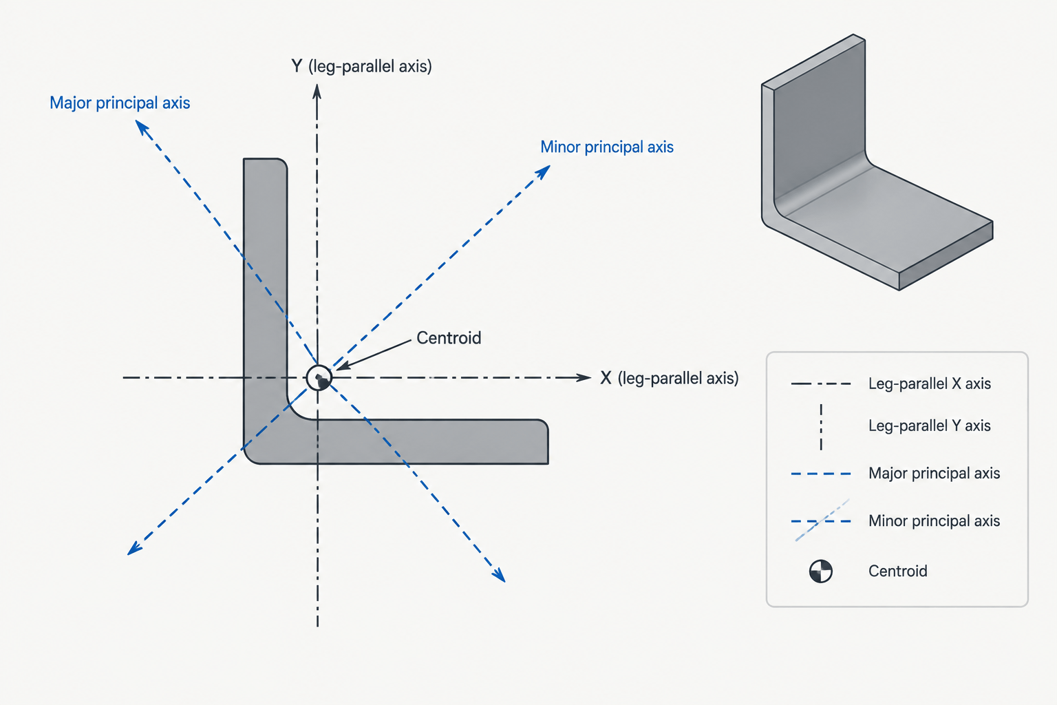
Consider a geometric x-y system through the angle’s centroid, with each axis parallel to one leg. These axes are convenient for dimensions and drafting, but they are not normally principal axes. The unequal distribution of area produces a nonzero product of inertia, commonly written as Ixy. As a result, bending referenced to one geometric axis can involve curvature in both geometric directions.
Rotating the centroidal axes to the principal orientation produces two important directions:
- The major principal axis, associated with the larger principal moment of inertia.
- The minor principal axis, associated with the smaller principal moment of inertia.
- A zero product of inertia between the two principal axes.
These axes are perpendicular to each other and pass through the centroid. They are section-property references, not physical centerlines, edges, or fabrication marks.
Geometric axes versus principal axes
| Reference | Typical purpose | Important limitation |
|---|---|---|
| Leg-based x-y axes | Dimensioning, locating the centroid, and reporting properties parallel to the legs | They generally have a nonzero product of inertia for a single angle |
| Principal axes | Understanding uncoupled bending and the extreme centroidal inertia directions | They are rotated and may be inconvenient for ordinary shop dimensions |
| Member or global model axes | Analysis orientation, loads, releases, and result reporting | They may not match either the leg-based or principal axes |
A common mistake is to see an x-axis in a section table and assume that it represents the strong bending direction. Axis letters alone do not establish that meaning. The accompanying section sketch determines the orientation, while the listed property values indicate which direction has greater stiffness.
Properties used to describe the rotated system
Centroid coordinates
An angle table may locate the centroid relative to the backs or outer faces of the legs. These offsets are essential when drawing centroidal axes. The outside corner, heel, toe, and leg centerlines are useful geometric references, but none should automatically be treated as the centroid.
Moments of inertia
Ix and Iy describe second moments of area about the stated x-y axes. Principal moments describe the same cross section about the rotated principal axes. The larger and smaller principal values are the extreme moments of inertia available among all centroidal axis orientations.
Product of inertia
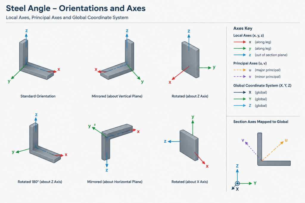
Ixy measures how the area is distributed jointly relative to two perpendicular axes. Its sign depends on the axis orientation and sign convention. Mirroring an angle can reverse the reported sign even though the physical section still has the same principal moment magnitudes.
The defining feature of a principal coordinate system is that its transformed product of inertia equals zero. Because sign conventions differ among references and software packages, users should not transfer a principal-axis angle or an Ixy sign without also transferring the source axis diagram.
Principal-axis angle
Some references report the rotation between a geometric axis and a principal axis. The angle must be interpreted with its stated starting axis, positive rotation direction, and section orientation. A bare rotation value is not enough to reconstruct the section correctly.
Radii of gyration
Principal radii of gyration are derived from the corresponding principal moments of inertia and the gross area. The minor principal radius is often important when considering the directional slenderness of an isolated angle. It should not be confused with a radius calculated about an axis parallel to a leg.
Equal-leg and unequal-leg angles
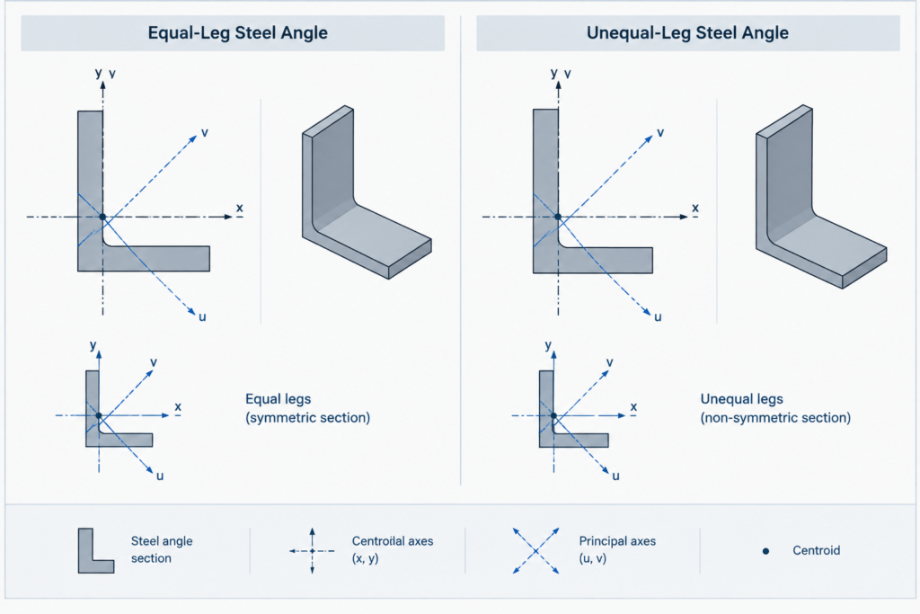
An ideal equal-leg angle has a line of symmetry along the bisector of its legs. That symmetry line is a principal axis, and the perpendicular centroidal direction is the other principal axis. Rolled fillets and corner geometry affect numerical properties, but they do not eliminate the ideal section’s equal-leg symmetry.
An unequal-leg angle does not have the same bisector symmetry. Its principal orientation must be obtained from verified section properties or calculated from the complete cross-sectional geometry. Simply drawing a diagonal between the legs or using a forty-five-degree rotation does not establish the principal axes.
Angle orientation also matters. Rotating an angle, flipping it, or mirroring it changes how its local axes relate to a building grid or analysis model. The principal property magnitudes remain properties of the shape, but axis directions and product-of-inertia signs must be mapped carefully.
How principal axes affect structural interpretation
If a bending moment acts about a principal axis, the resulting elastic bending description is comparatively direct because the principal-axis product of inertia is zero. If the applied moment is resolved about nonprincipal centroidal axes, the response is coupled. A load that appears to act in one drawing direction may therefore produce bending behavior involving both geometric axes.
This does not mean that every angle should be analyzed only in its principal system. Connection restraint, eccentric load paths, member end conditions, torsion, local effects, and code provisions may control the required analysis method. Principal properties describe the cross section; they do not by themselves describe the complete behavior of a connected member.
For double angles or other built-up arrangements, do not assume that the principal properties of one angle can simply be doubled. Spacing, orientation, connector arrangement, symmetry, and parallel-axis effects all influence the built-up section. The assembly needs its own centroid and section-property evaluation.
A practical shape-table and CAD workflow
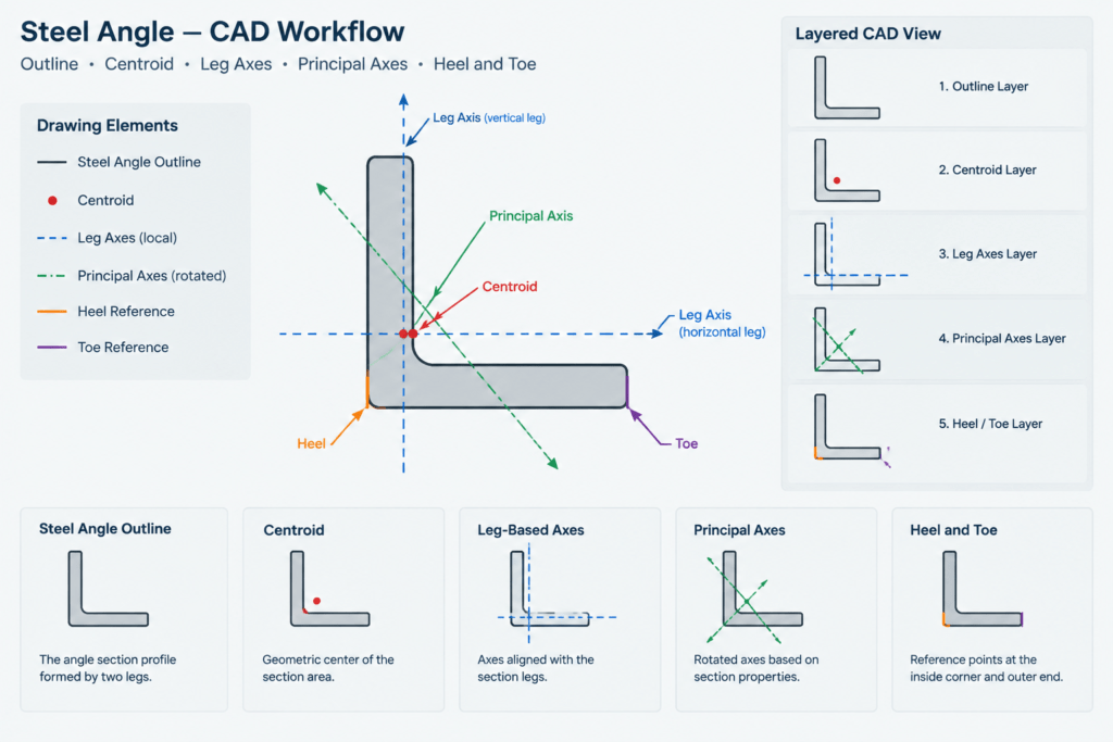
- Confirm the section orientation. Identify the long leg, short leg, heel, toes, and backs of legs from the source diagram.
- Locate the centroid. Use verified centroid offsets rather than estimating from the visible outline.
- Draw the source x-y axes. Match their positive directions and labels before entering any properties.
- Record the product-of-inertia convention. Preserve its sign only with the associated orientation diagram.
- Add the principal axes. Rotate them according to the verified principal-axis definition, not by visual judgment.
- Map local axes into the model. Check how the CAD or analysis program defines local member directions and angle insertion points.
- Verify a mirrored section separately. Confirm axis direction and sign changes instead of assuming copied data remains valid.
In CAD, it is helpful to place the section outline, centroid marker, geometric axes, and principal axes on separate layers. Keep axis graphics as construction information rather than part of the fabricated profile. A reusable angle block should also make its insertion point and orientation obvious; otherwise, rotating or mirroring the block can conceal a local-axis error.
Common errors to avoid
- Treating the intersection of the leg centerlines as the centroid.
- Assuming axes parallel to the legs are principal axes.
- Using a principal-axis angle without checking its rotation convention.
- Ignoring the sign change of
Ixywhen an angle is mirrored. - Applying single-angle properties directly to a back-to-back or separated double-angle member.
- Confusing the principal minor axis with the weakest global direction of a restrained assembly.
- Using a simplified sharp-corner CAD outline to regenerate properties intended to represent a rolled shape with fillets.
Key takeaway
The principal axes of a steel angle are rotated centroidal directions defined by the section’s area distribution. They are not automatically parallel to the legs, and their labels are not universal across tables and software. Reliable use of angle properties requires the property values, centroid location, axis sketch, rotation convention, and physical section orientation to be considered together. For project work, section data and modeling assumptions should be checked against the governing reference and the actual connection and restraint conditions.