Slotted and oversized holes can provide installation tolerance, accommodate intended movement, or support a project-specific connection detail. They also create a basic geometric issue: an ordinary washer may not adequately bridge the opening in every possible bolt position. A plate washer can provide broader bearing coverage, but its dimensions, restraint, and relationship to the slot must be deliberately coordinated.
For drafters and detailers, the important questions extend beyond whether a plate washer appears in a typical detail. The drawings must establish which ply contains the enlarged hole, where the plate washer is located, whether it is free or attached, and whether movement is supposed to remain possible after installation. These decisions affect the load path, bolt stack, fabrication, erection, and inspection of the connection.
What Is a Plate Washer?
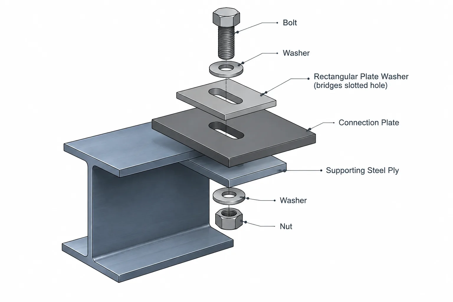
A plate washer is a plate-like component placed beneath a bolt head or nut to distribute bearing over a larger area than a conventional washer. It commonly has a round hole for the bolt, although its actual hole geometry must follow the connection design and project requirements.
The term can be ambiguous. Some project documents use “plate washer” for a standard product of a specified form, while others use it for a fabricated rectangular or square plate with a hole. A drawing should not rely on the name alone when the component’s size, thickness, material, hole, orientation, or attachment is important.
A plate washer is not automatically interchangeable with a conventional washer. It also should not be assumed to compensate for an incorrect hole, missing material, or unapproved field modification. The engineer’s connection requirements and applicable project documents control its use.
Why Enlarged Holes Change Washer Geometry
A round standard-size hole generally leaves material around the bolt in every direction. An oversized hole increases the opening around the bolt, while a slot extends the opening primarily along one axis. As the bolt moves away from the hole center, the bearing footprint under a washer can approach or cross the edge of the opening.
For a plate washer to bridge an enlarged hole, it needs sufficient overlap beyond the opening in the relevant bolt positions. Checking only the nominal centered position can be misleading. A slot intended to provide adjustment or movement should be reviewed with the bolt near both ends of the slot, not just at its midpoint.
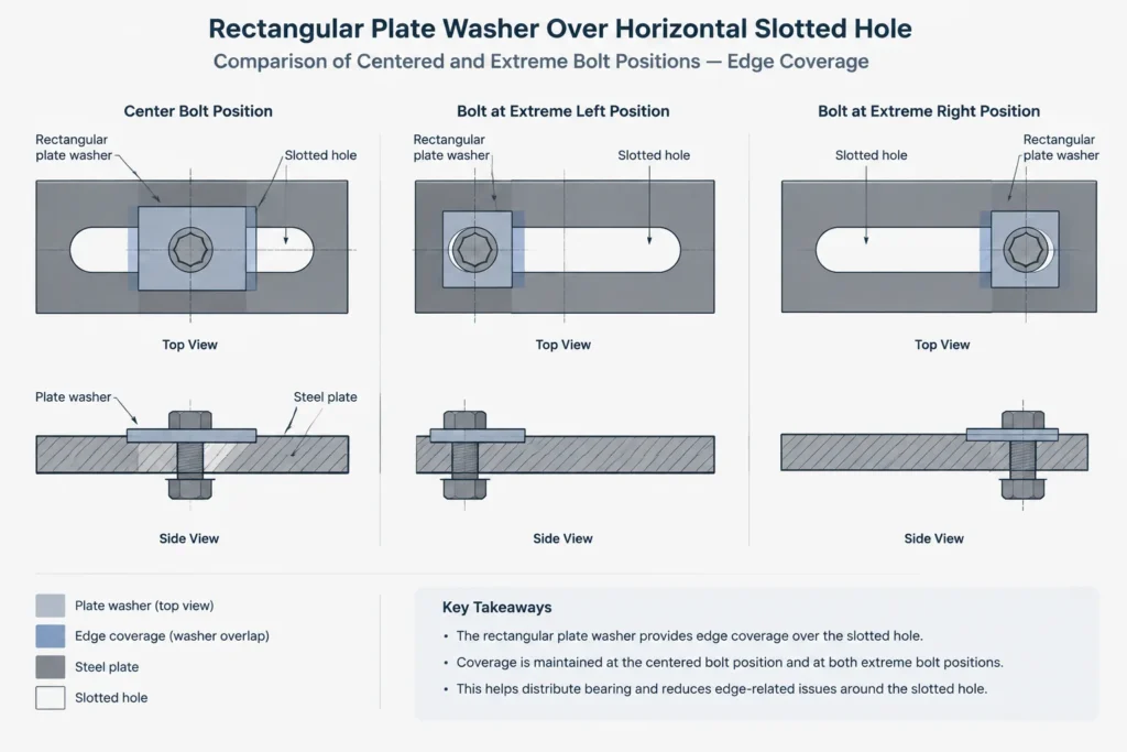
The supporting ply also matters. A plate washer that covers a slot in a thin connection plate may distribute local bearing differently from one placed over a thicker member flange. The required component and its structural function must come from the connection design rather than a drafting convention.
Identify Which Ply Contains the Slot
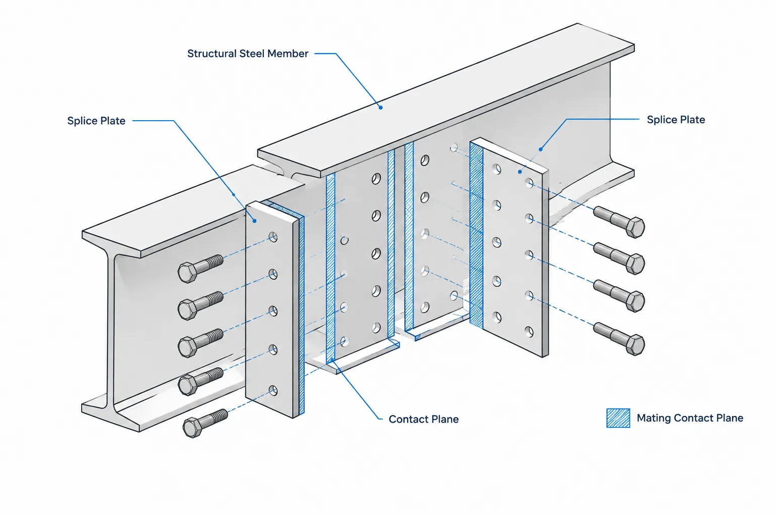
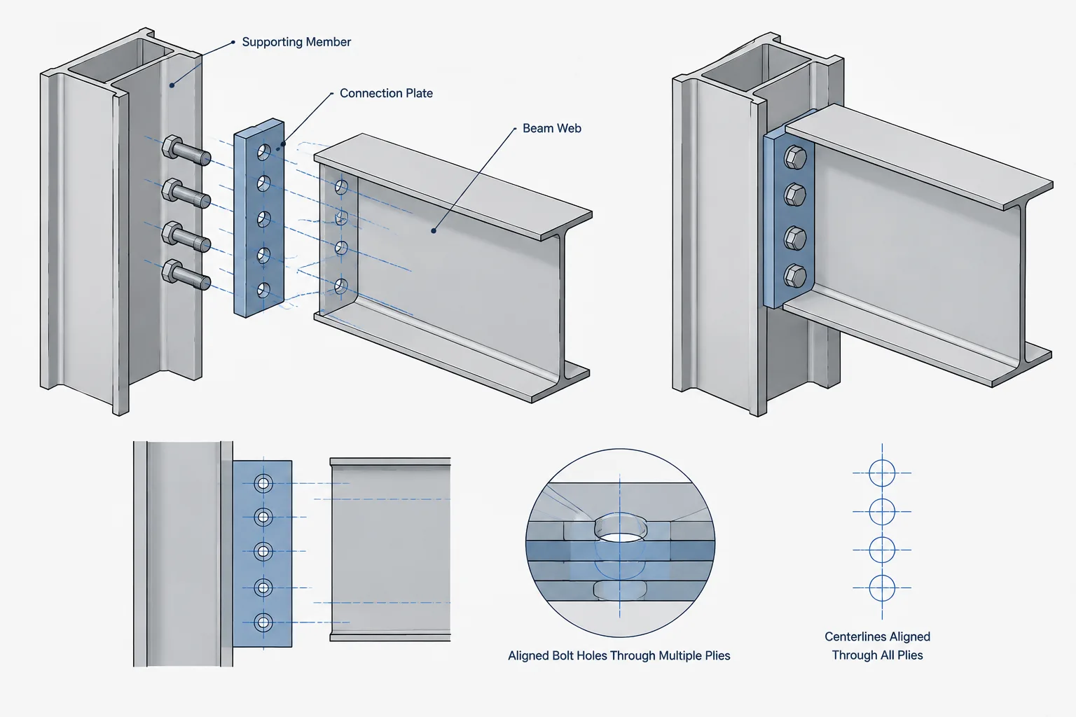
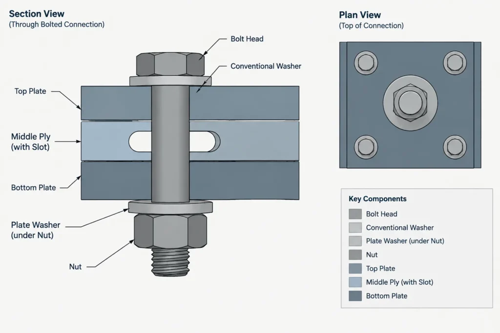
A bolted connection may contain several plies: a beam web, connection plate, gusset, angle, flange, splice plate, or supporting member. A slot shown in one elevation can be incorrectly interpreted as passing through every ply unless the drawings distinguish the parts.
Before detailing the plate washer, identify:
- the part or ply containing the slot or oversized hole;
- whether the mating plies contain round holes, enlarged holes, or another approved hole type;
- whether the plate washer belongs under the bolt head, under the nut, or at another specifically directed location;
- which surface is accessible for installation and tightening;
- whether the bolt is expected to occupy a centered or offset position during erection; and
- whether the connection is intended to permit movement in service.
A section through the complete bolt stack is often clearer than a plan symbol alone. The section can show the enlarged-hole ply, washer location, nut side, bolt head side, and any intervening plates.
Movement Slot vs. Erection-Tolerance Slot
Not every slot has the same purpose. A slot may provide temporary erection adjustment, or it may be part of a connection intended to accommodate movement. That distinction changes how the plate washer should be interpreted.
Erection-tolerance condition
In an erection-tolerance condition, the slot may allow parts to align before final tightening. The completed connection is then expected to act in the manner defined by the design documents. The plate washer’s role may be to maintain coverage at the final bolt position and provide the intended bearing surface.
Movement condition
In a movement connection, the slotted interface may need to remain capable of relative displacement. A plate washer that is unintentionally welded, trapped, or detailed so that it bears against an obstruction can defeat that movement. The slot direction, expected displacement path, contacting surfaces, and attachment instructions must therefore be coordinated as a system.
Neither condition should be inferred solely from the shape of the hole. Notes, connection schedules, design details, and engineering intent should establish the slot’s purpose.
Free, Captive, and Welded Plate Washers
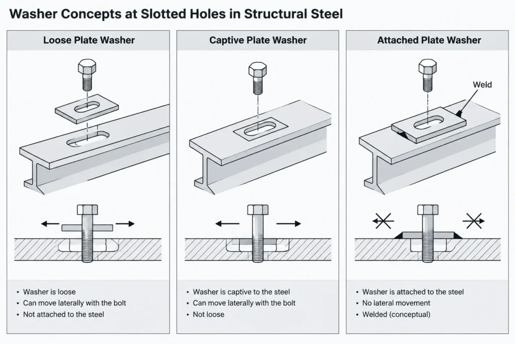
The restraint condition of a plate washer is a key detailing issue. Common conceptual arrangements include a loose washer, a washer made captive for handling, and a washer intentionally attached to another part. These arrangements are not equivalent.
| Arrangement | Detailing concern | Coordination question |
|---|---|---|
| Loose plate washer | Can shift or rotate before tightening | Will it remain accessible and cover the enlarged hole at the installed bolt position? |
| Captive washer | Retention feature may restrict travel | Does the retention method preserve the intended adjustment or movement? |
| Attached washer | Attachment becomes part of the load path and geometry | Is attachment required, and where may it occur without blocking the slot or conflicting with the design? |
Welding should never be added merely because a loose part seems inconvenient. A weld can restrain the washer, affect coated surfaces, create access problems, and change how movement occurs. If attachment is required, the drawing should clearly identify what is welded to what, where the attachment is permitted, and whether the washer remains able to move relative to the bolt or connected ply.
Plate Washer Orientation and Edge Coverage
Rectangular plate washers have an orientation even when their bolt hole is centered. One dimension may be selected to bridge the slot width, while the other provides coverage along the slot as the bolt position changes. Rotating the plate washer can therefore change its effectiveness.
A useful CAD check is to overlay the plate washer on the full slot envelope. Move the bolt and washer to each permitted extreme and inspect the remaining overlap around the opening. Also check nearby edges, welds, stiffeners, flanges, bend radii, and other bolt assemblies. A plate washer that covers the hole may still be impossible to install because it clashes with adjacent geometry.
If orientation is controlling, show it graphically or dimension it from a stable datum. Do not assume that a square-looking symbol in a small-scale view communicates the intended arrangement.
Bolt Stack-Up and Installation Access
Adding a plate washer changes the bolt stack. The detailer should account for every ply, conventional washer, plate washer, nut, and any other specified component when coordinating bolt length and access. A thick or doubled washer arrangement can alter thread location, available projection, and wrench clearance.
Installation sequence also matters. Ask whether the plate washer can be inserted after the steel is positioned, whether gravity will cause it to fall or rotate, and whether a nut or bolt head can be reached with the connected members in place. In congested assemblies, a correct two-dimensional detail can still be impractical in the shop or field.
Coatings, Contact Surfaces, and Drainage
Plate washers can create concealed contact areas where coatings, moisture, debris, or sealants accumulate. Project coating requirements may apply differently to loose parts, attached components, and faying surfaces. The detailer should avoid making assumptions about masking, painting, galvanizing, or surface preparation.
For exterior or exposed connections, review whether the washer arrangement creates a pocket that retains water. Orientation, attachment, and surrounding geometry can affect drainage. Any change intended to improve drainage must remain consistent with the engineered connection and coating system.
Recommended Drawing Information
A complete detail does not need to repeat every project specification, but it should communicate the geometry and placement that cannot safely be inferred. Depending on the connection, useful information may include:
- plate washer part mark or clear component identification;
- overall plate dimensions and thickness from verified design information;
- washer hole type and location;
- slot direction and the ply in which the slot occurs;
- location beneath the bolt head or nut;
- required orientation relative to the slot;
- free, captive, or attached condition;
- attachment instructions when specifically required;
- quantity per connection or bolt location; and
- relevant coating or surface-treatment notes from the project documents.
Use part and assembly views together. The part drawing defines the plate washer itself, while the assembly view establishes its installed side and orientation. A section is especially useful when the enlarged hole is hidden behind another ply.
A Practical CAD and Checking Workflow
- Model the complete ply stack. Represent each connected part separately rather than using a single merged outline.
- Assign the correct hole to each ply. Confirm that slots and oversized holes have not propagated into parts that should have different holes.
- Establish the slot axis. Relate it to the intended adjustment or movement direction.
- Place the plate washer on the specified side. Check both plan geometry and the section through the bolt.
- Test extreme bolt positions. Review hole coverage and clashes throughout the permitted travel envelope.
- Review the stack-up. Include all washers and connection plies when coordinating bolt length and tool access.
- Confirm restraint. Verify whether the washer is loose, retained, or attached and whether that condition conflicts with movement.
- Cross-check every output. The model, shop drawing, bolt list, bill of material, and fabrication data should describe the same arrangement.
Final Coordination Principle
A plate washer is a small part with a potentially important role. Its effectiveness depends on more than its outline: the enlarged-hole ply, possible bolt positions, orientation, restraint, stack-up, and connection purpose all matter. The safest detailing approach is to treat the washer, slot, and bolt as one coordinated assembly rather than as independent symbols.
When the design intent is unclear, do not resolve the ambiguity by selecting a convenient plate size or adding a weld. Flag the issue for engineering or project-specific clarification, then document the verified arrangement consistently across the structural steel drawings and fabrication information.