The centroid and the plastic neutral axis are both reference locations used in structural steel calculations, but they represent different physical conditions. They coincide in many symmetric shapes, which can make them seem interchangeable. In unsymmetric sections such as structural tees, channels, and angles, however, their locations can be noticeably different.
Understanding the distinction is especially useful when reading section-property tables, checking a CAD-derived plastic section modulus, or evaluating a built-up cross-section. The centroid belongs primarily to elastic section analysis. The plastic neutral axis belongs to an idealized fully yielded bending condition.
What the centroid represents
The centroid is the geometric balance point of a cross-sectional area. For a homogeneous steel section in linear-elastic bending, the neutral axis passes through the centroid. Fibers on one side of that axis are in tension, while fibers on the other side are in compression. Stress varies linearly with distance from the neutral axis.
Centroid coordinates are calculated from first moments of area. For an area divided into convenient components, a centroid coordinate can be written conceptually as:
ȳ = Σ(Aiyi) / ΣAi
Each component area is multiplied by the location of its own centroid relative to the selected datum. The result depends on geometry, not on whether the area above and below the centroid is equal.
This last point is important: a centroid balances first moments of area. It does not generally divide a section into two equal areas.
What the plastic neutral axis represents
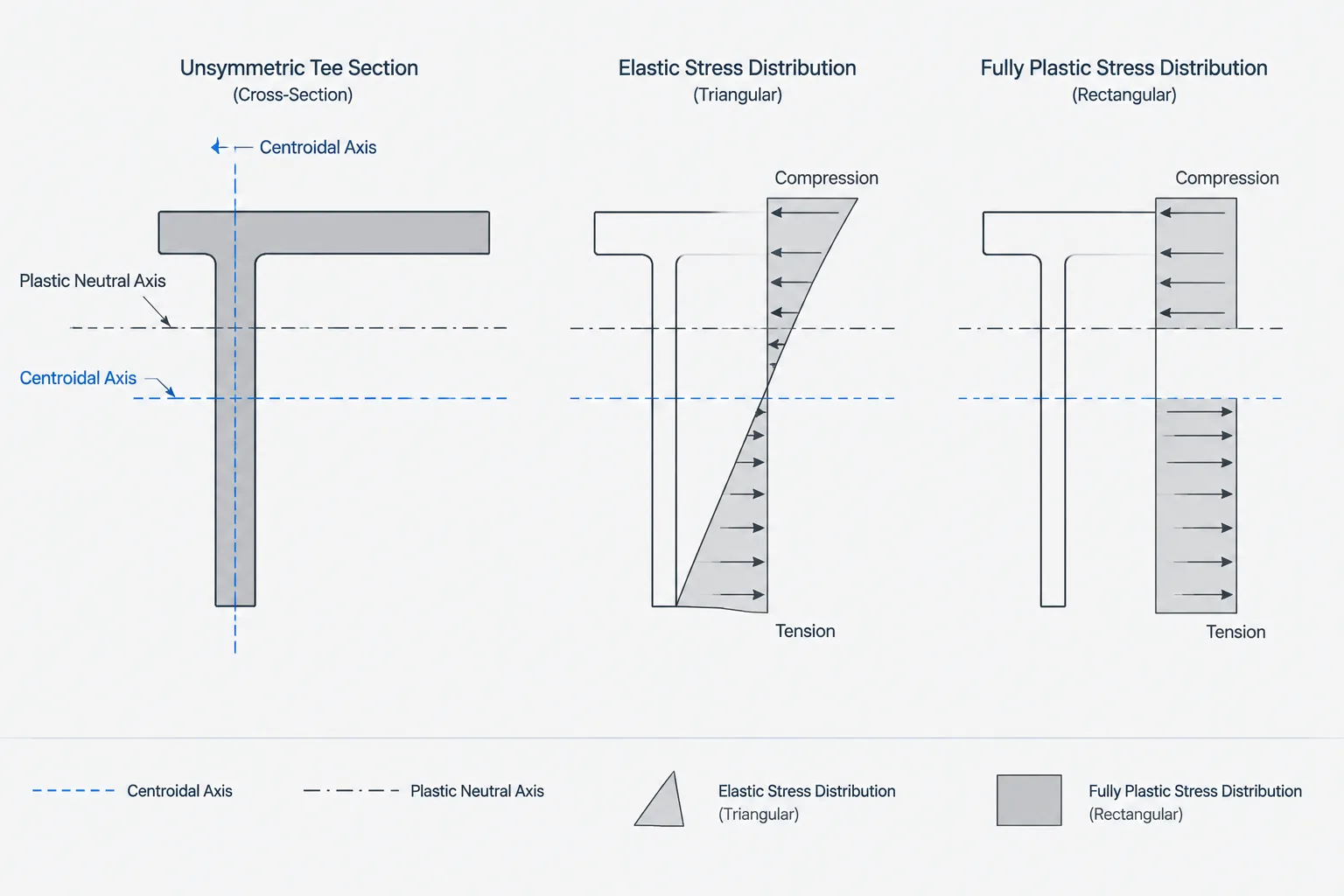
The plastic neutral axis, commonly abbreviated PNA, is associated with an idealized fully plastic stress distribution. Under pure bending of a homogeneous steel section, one side of the PNA is assumed to have reached uniform tensile yield stress and the other side uniform compressive yield stress.
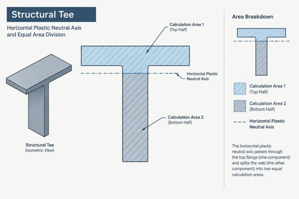
For those forces to balance when there is no net axial force, the total tensile force must equal the total compressive force. If the material has the same yield strength in tension and compression, that force balance means the PNA divides the cross-sectional area into two equal halves.
This is an area-balance requirement rather than a first-moment balance:
Area on the tension side = area on the compression side = one-half of the total area
The PNA may pass through a flange, web, leg, or other part of the section. Its location depends on how the cross-sectional area is distributed relative to the bending direction.
Why the two locations can differ
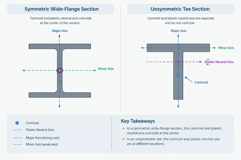
For a doubly symmetric W-shape bent about either centroidal symmetry axis, the centroid and PNA normally coincide. Each applicable axis divides the area symmetrically, so both the first-moment condition and the equal-area condition are satisfied at the same location.
An unsymmetric section behaves differently. Consider a structural tee oriented with its flange at the top. A large portion of the area may be concentrated in the flange. The centroid shifts toward that flange because of the area’s moment about the datum. The PNA must instead be positioned where half of the total area lies on each side. Depending on the flange and stem proportions, it may fall within the flange or the stem and need not pass through the centroid.
| Reference | Defining condition | Primary use | Does it divide area equally? |
|---|---|---|---|
| Centroid | Balances first moments of area | Elastic bending and centroidal properties | Not necessarily |
| Elastic neutral axis | Location of zero longitudinal elastic bending stress | Linear-elastic stress calculations | Not necessarily |
| Plastic neutral axis | Balances fully yielded tensile and compressive forces | Plastic section modulus and plastic bending models | Yes, for homogeneous material with equal tensile and compressive yield strength and no axial force |
Relationship to plastic section modulus Z
Plastic section modulus, designated Z, measures the fully plastic bending contribution of the cross-sectional area about a selected axis. Once the PNA is known, the section can be divided into area components on its two sides. The first moment of each component is then taken about the PNA.
A useful general expression is:
Z = ∫ |y − yPNA| dA
For a section decomposed into rectangles or other simple regions, this becomes a sum of each component area multiplied by the distance from its centroid to the PNA. Components crossed by the PNA must be split so that the correct distance is used for each portion.
Under an idealized homogeneous, fully yielded uniaxial bending model, the plastic moment is related to yield stress and plastic section modulus by Mp = FyZ. This relationship does not by itself establish the usable strength of a member. Local buckling, lateral stability, connection behavior, section classification, applicable design provisions, and other limit states still require evaluation.
A practical calculation workflow
1. Confirm the bending axis and orientation
Identify the physical top, bottom, left, and right of the section. Do not rely only on generic x- and y-axis labels, because software and published references may use different local-axis conventions.
2. Determine the total cross-sectional area
Use verified published area data when checking a rolled shape. For a built-up or idealized section, divide the geometry into nonoverlapping components and sum their areas. Avoid double-counting intersections between plates.
3. Find the half-area target
For a homogeneous section under pure bending, half of the total area must lie on each side of the PNA. Starting from one extreme edge, accumulate area until the half-area target is reached.
4. Locate the PNA within the intersected component
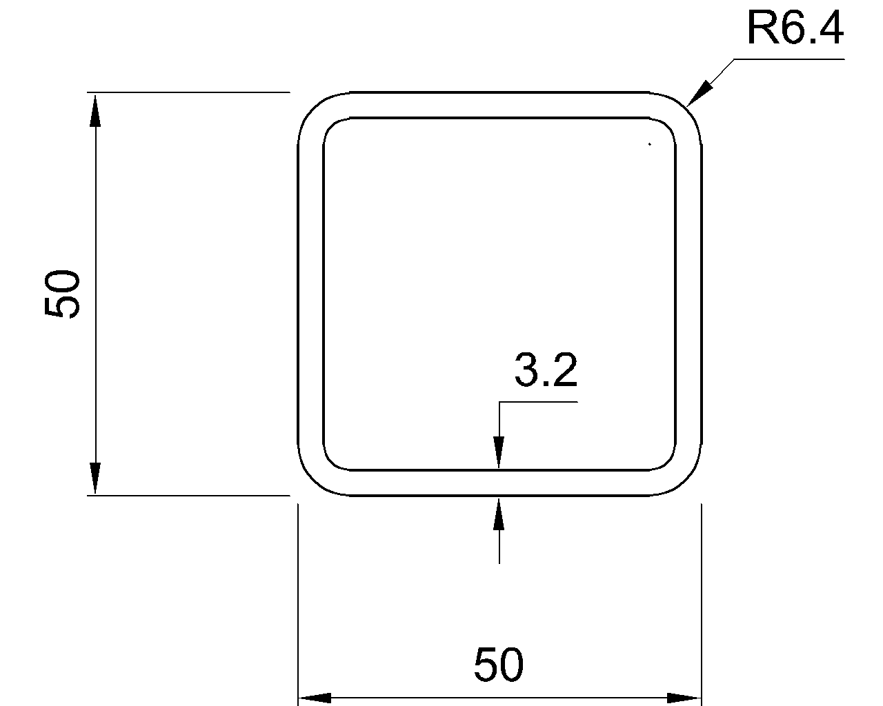
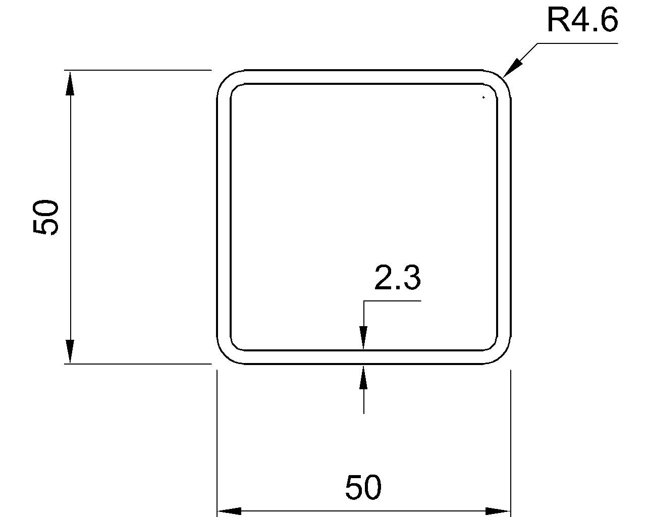
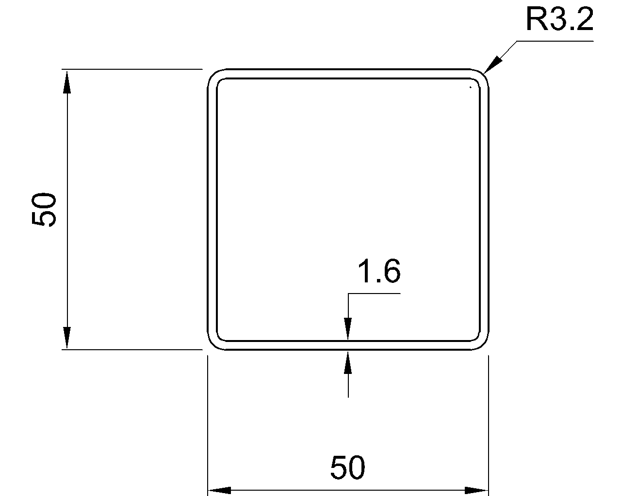
The half-area point often falls inside a flange, web, or plate rather than at a component boundary. Solve for the required partial area within that component. Rolled fillets and rounded HSS corners can make an exact hand calculation more involved than a sharp-corner approximation.
5. Calculate first moments about the PNA
Split any region crossed by the PNA. Multiply each resulting area by the perpendicular distance from its centroid to the PNA, and sum the contributions. Distances are treated as positive magnitudes when calculating Z.
6. Compare like with like
When checking a published value, confirm that the same section geometry, axis, orientation, and units are being used. A simplified CAD profile may omit rolled fillets or use nominal corner geometry, causing its area, PNA location, and Z value to differ from published properties.
Common mistakes in CAD and spreadsheet checks
- Using the centroid as the PNA automatically: This works for appropriate symmetric sections but can be wrong for tees, angles, channels, and many built-up members.
- Asking CAD only for centroidal properties: A region-properties command may report area, centroid, and moments of inertia without directly identifying the plastic neutral axis or plastic section modulus.
- Failing to split an area crossed by the PNA: Treating that area as one component places its entire first moment on a single side of the axis.
- Ignoring modeled geometry differences: Sharp corners, omitted fillets, weld material, and overlapping plate regions can change the result.
- Mixing axis labels: Z about one axis cannot be compared with a table value about the other axis merely because both are labeled “plastic section modulus.”
- Applying the equal-area rule to mixed materials: If parts have different yield strengths, equilibrium is based on yielded force, not unweighted area alone.
What changes when axial force is present?
The simple equal-area PNA rule assumes pure bending with no resultant axial force. When axial tension or compression acts together with bending, the yielded compression and tension resultants no longer need to be equal. The stress-block boundary shifts to satisfy combined force and moment equilibrium.
That combined condition should not be confused with the tabulated Z of a shape. Published plastic section properties generally describe a section bent about a stated axis under the assumptions associated with that property, not every possible axial-force and bending interaction state.
Using shape tables and CAD together
Published steel-shape data should remain the primary reference for the properties of recognized rolled shapes. CAD is most useful as an independent visualization and checking tool: it can confirm orientation, show why the PNA moves, and support calculations for custom built-up sections.
For a reliable check, document the profile source, unit system, bending axis, datum, PNA location, and any geometric simplifications. A close comparison is meaningful only when the CAD model and the table describe the same cross-section.
The key distinction is straightforward: the centroid balances first moments, while the plastic neutral axis balances yielded forces. They may share a location in symmetric sections, but they answer different questions and should be calculated for the condition actually being studied.