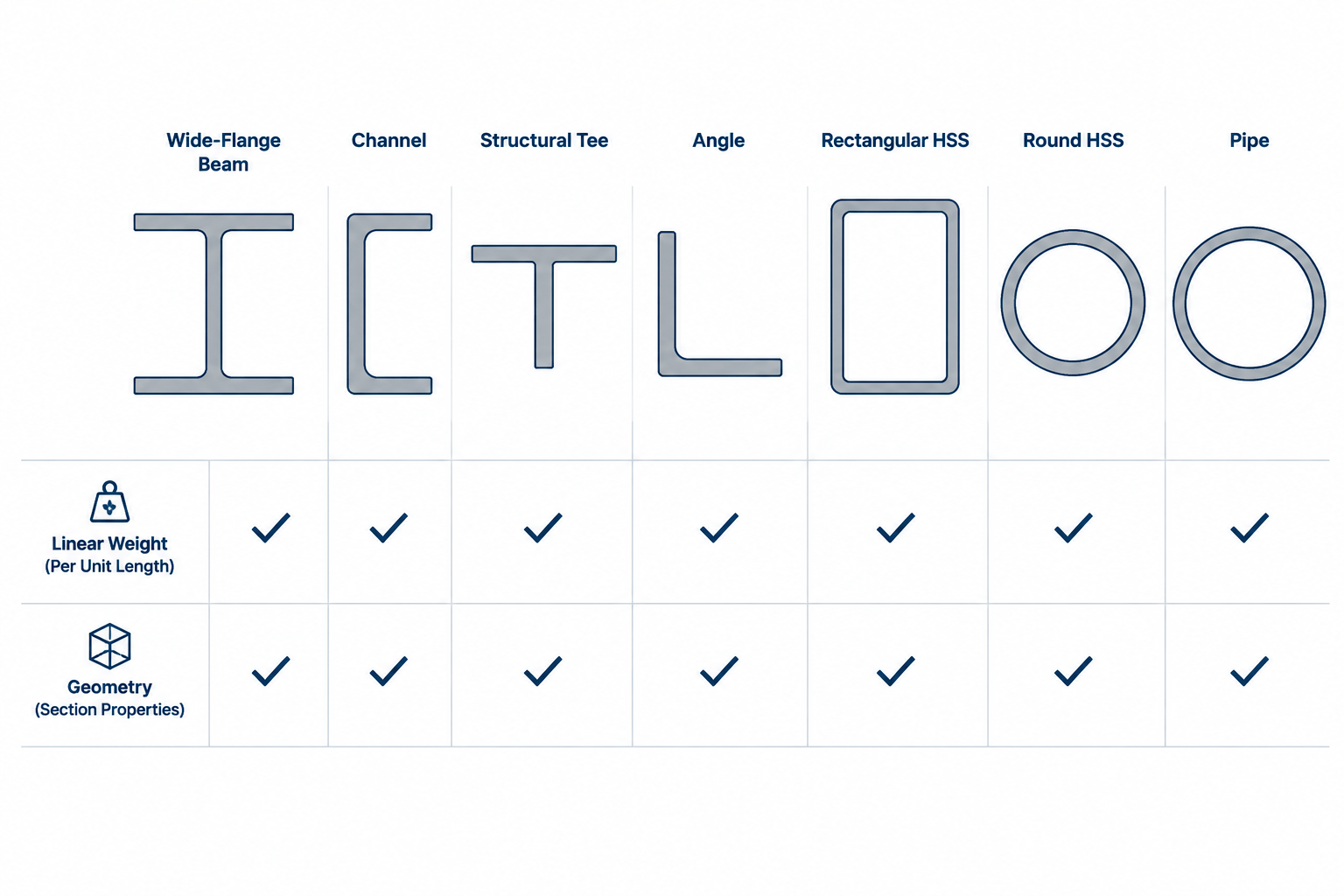
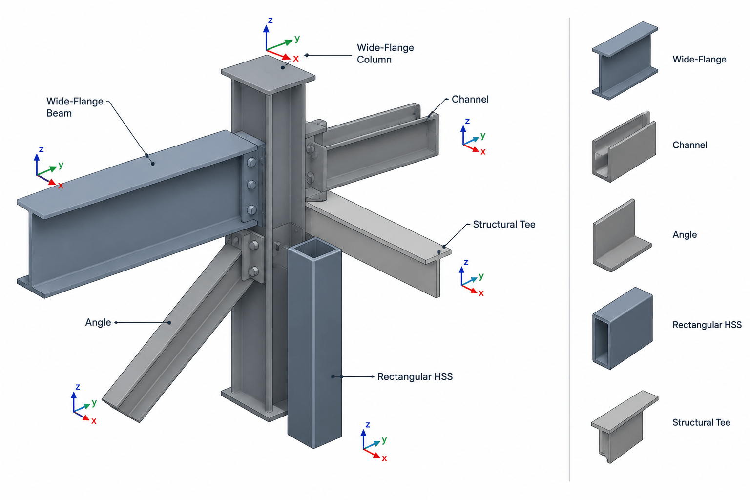
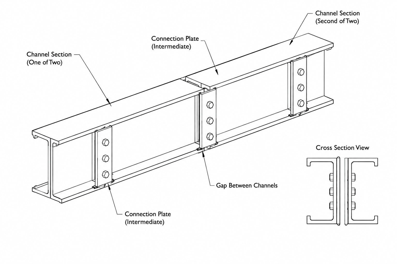
The PFC 180x90x26 is a parallel flange channel profile used as a reference shape in structural steel design, detailing, fabrication, and CAD work. This page lists the source dimensions and section data for the profile, together with an engineering drawing download.
Use the values below when checking section identification, preparing drawings, or comparing channel profiles. For design work, confirm material grade, load effects, restraint conditions, connection details, and applicable design requirements with the responsible engineer.
PFC 180x90x26
Parallel Flange Channels
refer to : EN 10365:2017
a European standard that defines the dimensions, tolerances, and sectional properties for hot-rolled steel channels, I-beams, and H-beams used in construction and engineering. It ensures uniformity and compatibility across European structural steel products.
Dimension : 180x90x6.5×12.5
Depth : 180 mm
Width : 90 mm
Web Thickness : 6.5 mm
Flange Thickness : 12.5 mm
Root Fillet Radius : 12 mm
Sectional Area : 33.2 cm2
Unit Weight : 26.1 kg/m
How to read the PFC 180x90x26 designation
The designation identifies a parallel flange channel by its nominal depth, flange width, and approximate mass designation. The detailed source data below separates the overall dimensions from the web, flange, and root-fillet geometry used to describe the rolled section.
Profile geometry and section data
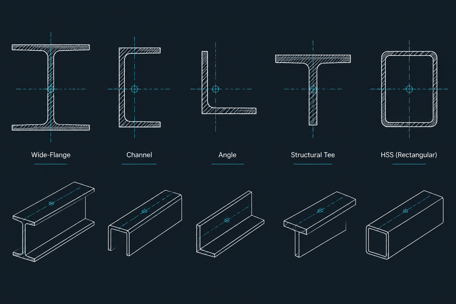
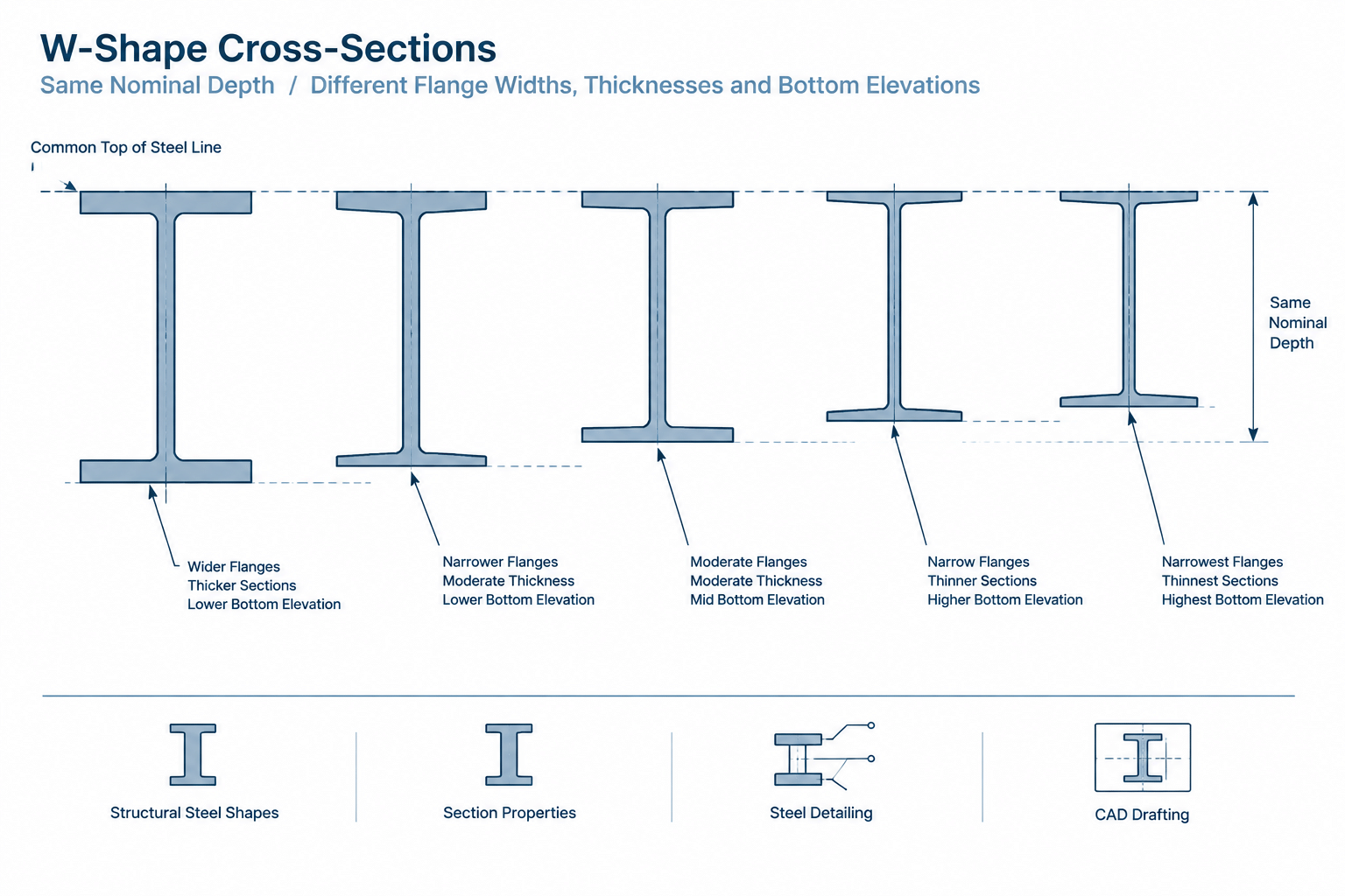
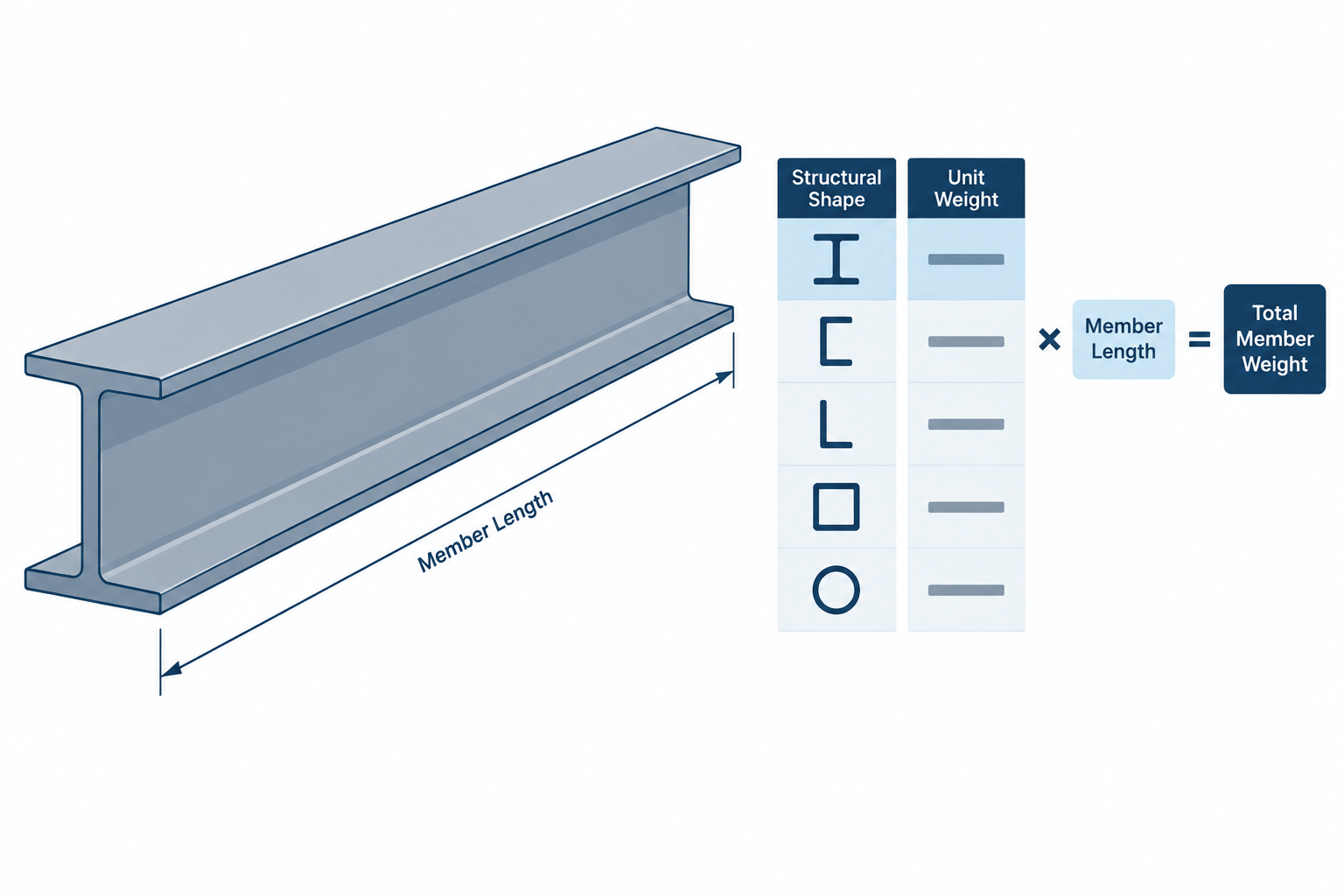
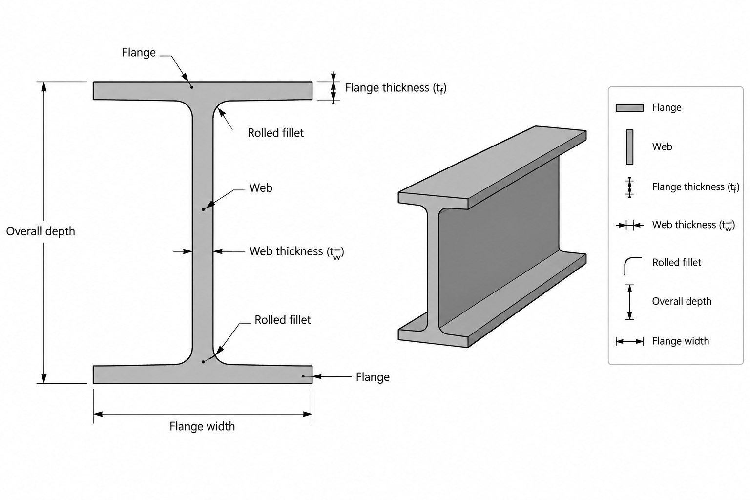
Channel geometry affects how the section behaves in bending, compression, shear, connection detailing, and fabrication. The listed depth and width describe the overall envelope, while web thickness, flange thickness, and root fillet radius describe important local features of the rolled shape. The sectional area and unit weight are useful for quantity takeoffs and preliminary comparisons, but they do not by themselves establish design resistance.
Using the standard reference
The page identifies EN 10365:2017 as the dimensional and sectional-property reference for this profile family. Standards references help coordinate section naming and product geometry, but project specifications may also require separate checks for steel grade, tolerances, corrosion protection, fabrication, and design code requirements.
CAD and detailing workflow
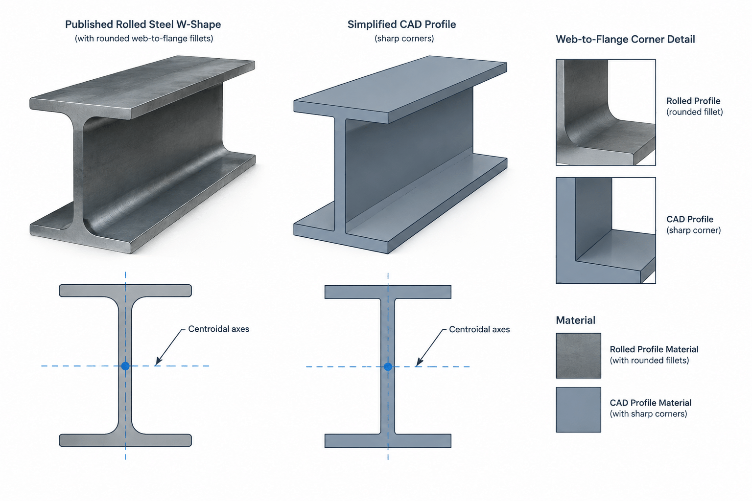
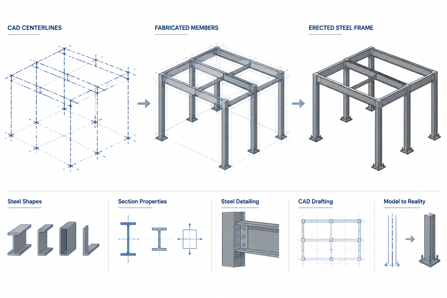
The downloadable DWG can support drafting and coordination workflows where a channel outline is needed. Before using imported geometry in fabrication or analysis documents, check the drawing units, insertion scale, profile orientation, section rotation, and the way the root fillets are represented. Keep the source dimensions alongside the CAD file so that the model remains traceable to the reference data.
For related research, connect this profile with resources on structural steel shapes, section properties, steel channel connections, and CAD blocks for steelwork. These topics help distinguish geometric reference information from the calculations required for member and connection design.
Frequently asked questions
What does PFC mean?
PFC means Parallel Flange Channel. It describes a channel section with flanges arranged as parallel elements rather than the tapered flange geometry found in some other channel families.
What information is provided for the PFC 180x90x26?
The source lists the profile designation, standard reference, overall dimensions, web and flange thicknesses, root fillet radius, sectional area, and unit weight.
What is EN 10365:2017 used for on this page?
It is the cited reference for the dimensions, tolerances, and sectional properties associated with the listed hot-rolled channel profile family.
Can the DWG be used directly for structural design?
The DWG is a drafting reference and does not replace engineering verification. Check its scale and orientation, then verify material, loading, restraint, connection, and code requirements before using the profile in a design.
Does the unit weight determine the channel’s design capacity?
No. Unit weight supports material estimation and weight calculations. Design capacity depends on the complete engineering assessment, including geometry, material, loading, stability, restraint, and connection conditions.