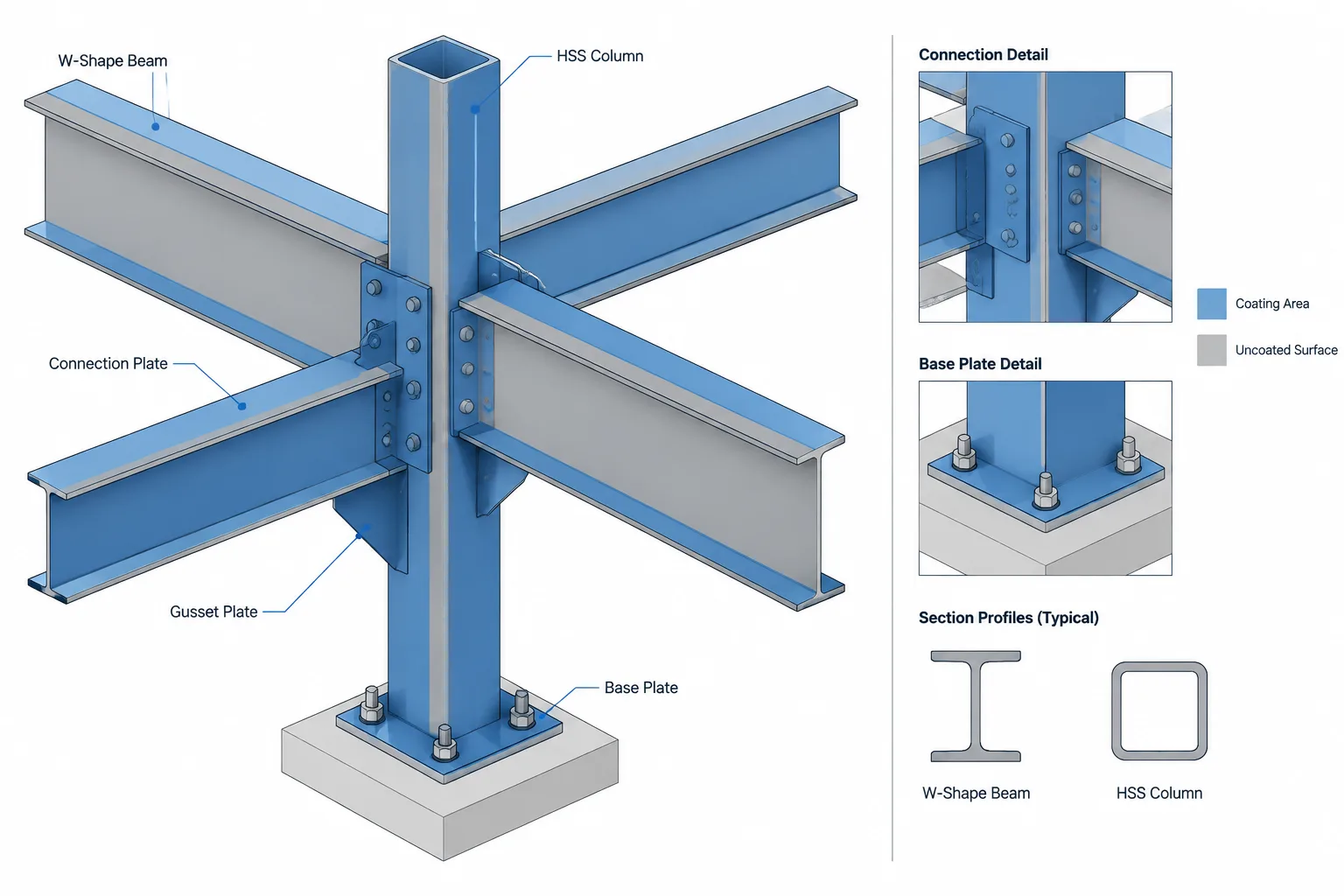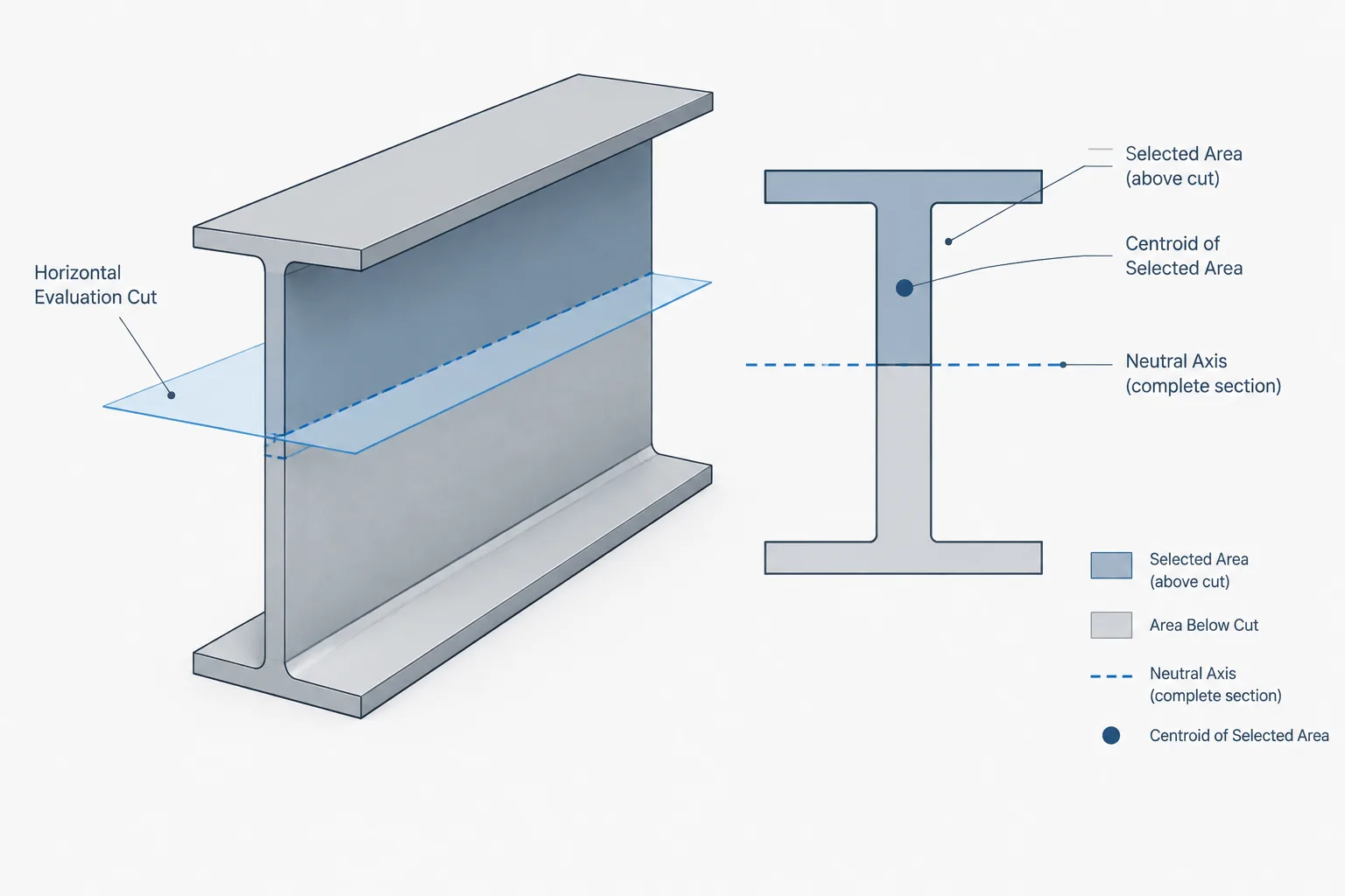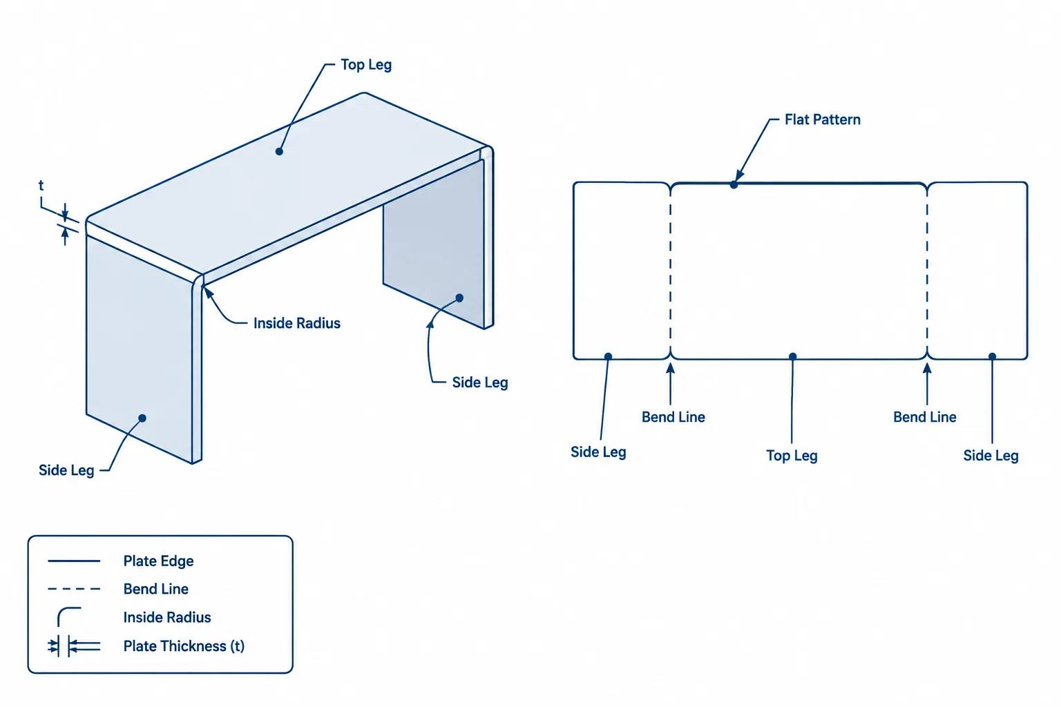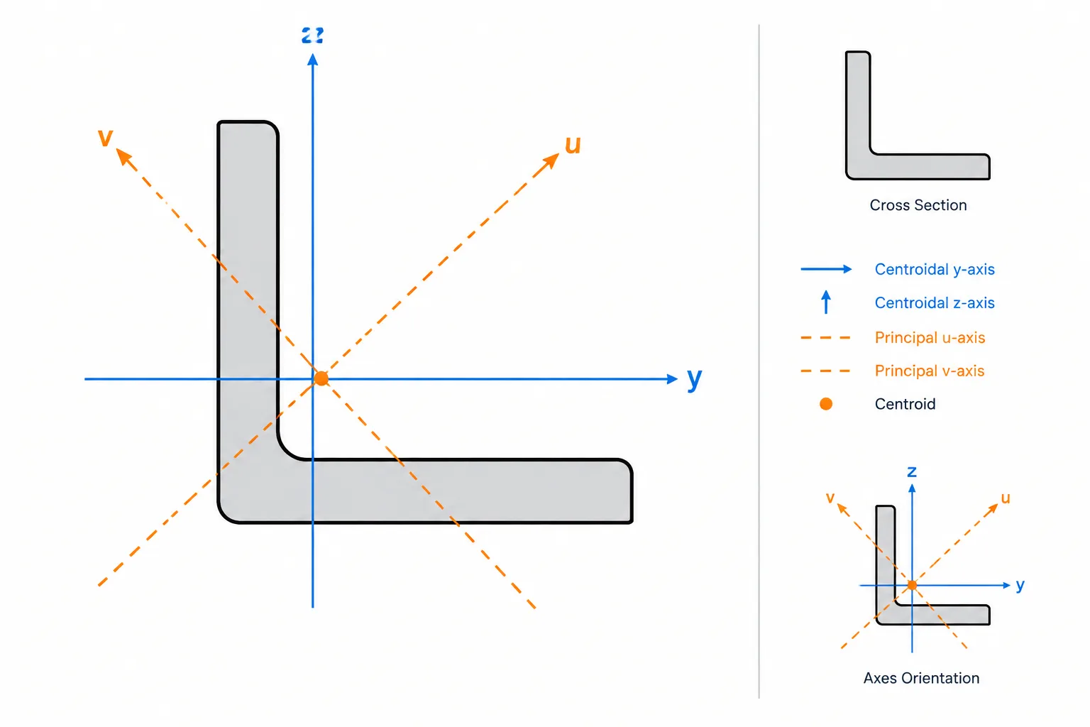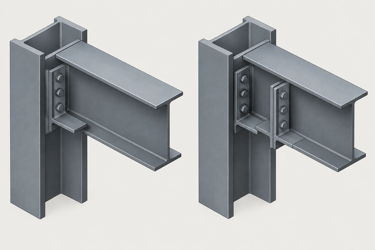
A rolled steel shape may be geometrically symmetric, but the fabricated member made from it may not be. Connection plates, clip angles, stiffeners, holes, seats, tabs, and other attachments can turn an otherwise ordinary beam or column into a handed assembly. If its mirror image cannot be installed in the same location and orientation, the difference must be recognized in the model, shop drawings, bills of material, and piece-mark system.
Handed structural steel assemblies deserve special attention because they often look nearly identical in plan or elevation. A mirrored copy may pass a quick visual review while placing a connection on the wrong face, reversing an angle, or shifting an asymmetric hole pattern. Clear reference directions and deliberate CAD checks are more reliable than labels such as left and right by themselves.
What Makes a Steel Assembly Handed?
An assembly is handed when reflecting its geometry creates a physically different part. In practical terms, the left-hand and right-hand versions cannot be substituted without changing their installed orientation, connection arrangement, or relationship to the structure.
Common causes include:
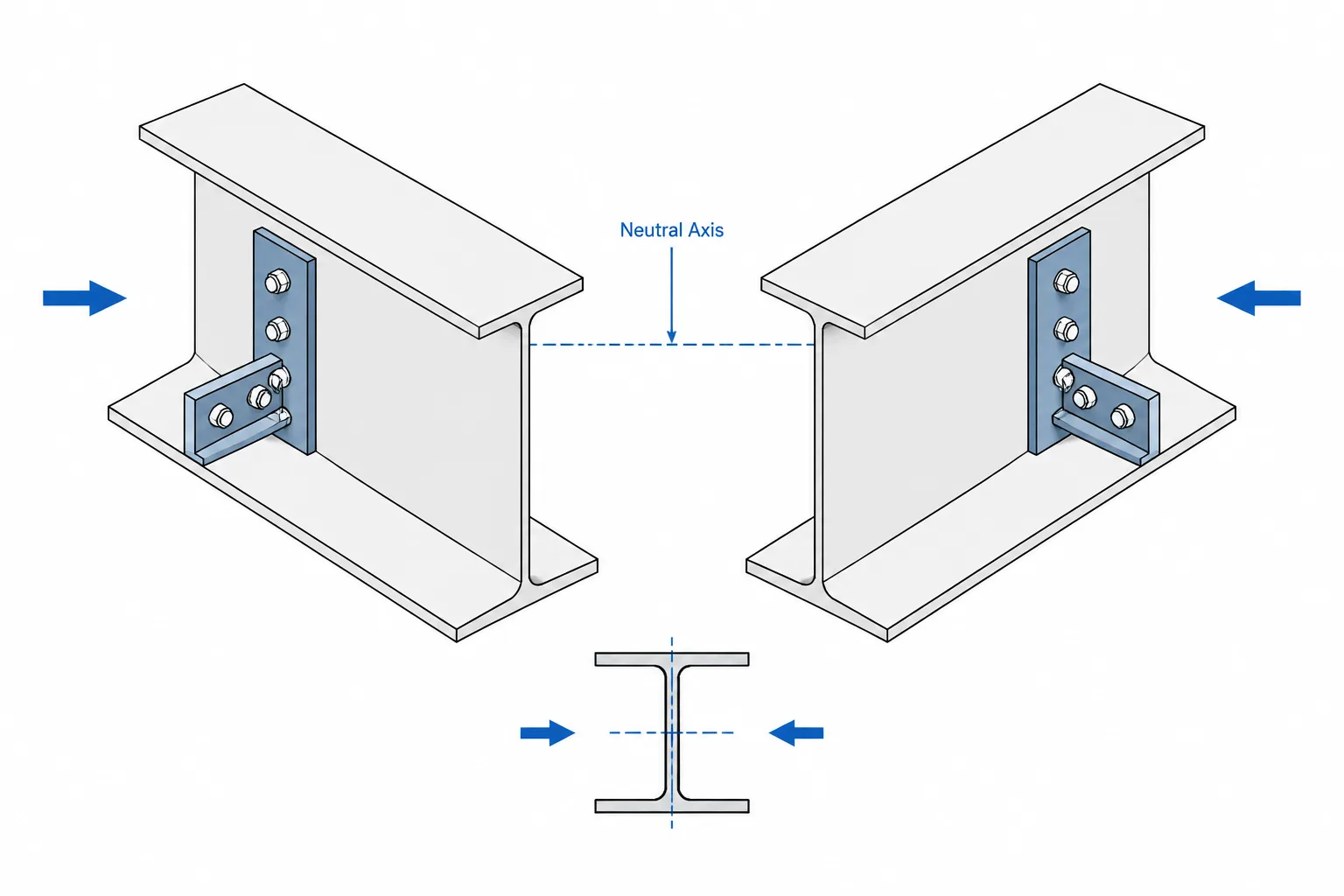
- A shear plate or clip angle attached to only one side of a beam web.
- A seat, bracket, or connection plate offset from the member centerline.
- Unequal attachment layouts at opposite ends of a member.
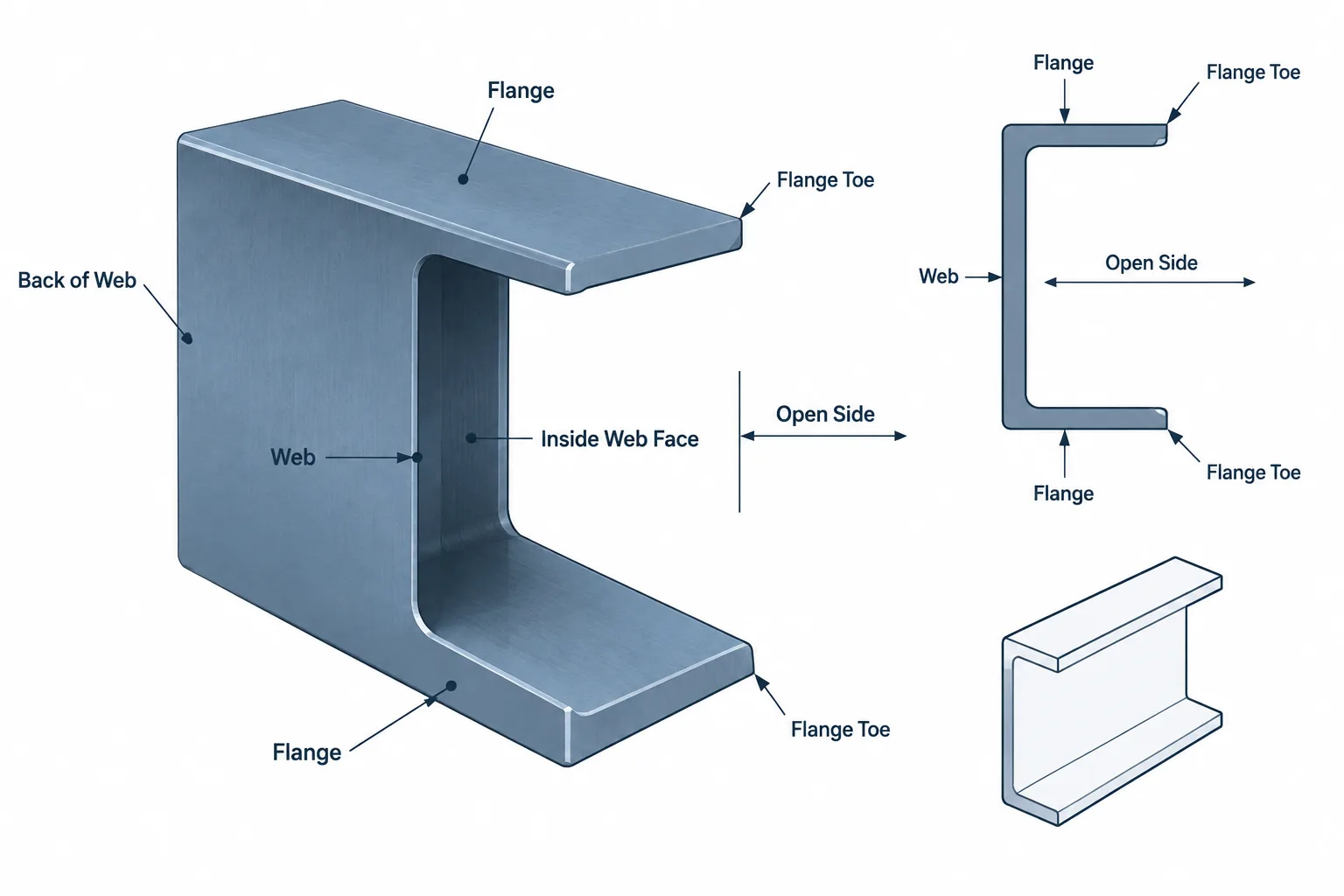
- A channel with its open side facing a required direction.
- An angle with a particular leg connected or outstanding.
- HSS with plates, slots, holes, or weld seams coordinated to specific faces.
- A column with stiffeners or connection material on selected flanges.
- A base plate with a nonsymmetric anchor-rod or shear-lug arrangement.
- A stair, canopy, equipment-support, or edge framing member that follows one side of a layout.
The rolled section itself does not need to be asymmetric. A W-shape may have a symmetric cross section, yet a single plate welded to one web face makes the resulting assembly potentially handed.
Rotation Is Not the Same as Reflection
One of the most useful checks is to separate rotation from reflection. A physical member can be rotated in space without changing its fundamental handedness. Reflection creates mirror-image geometry and can produce a different fabricated assembly.
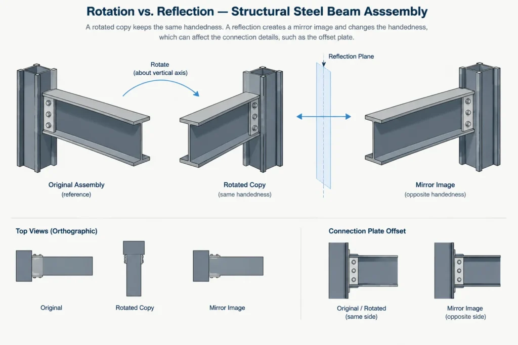
However, whether a rotated member is usable in another location depends on more than shape alone. Turning a beam end for end may exchange its start and end conditions. Flipping it may move top attachments to the bottom or place a plate on the opposite side of the web. A model that appears to align after rotation may still conflict with elevations, connection faces, or erection access.
Do not assume that a copied assembly is interchangeable merely because its overall length and main shape match. Compare the complete attachment arrangement relative to stable references.
Why Left and Right Can Be Ambiguous
The terms left-hand and right-hand are useful only when the viewing direction is defined. A plate shown on the left side of a member in one elevation may appear on the right when viewed from the opposite end. Similar confusion occurs when plan views, shop elevations, and three-dimensional model views use different directions.
A dependable handedness definition should identify references such as:
- The grid direction or framing-line direction.
- The member start and end.
- The view direction for the shop elevation.
- Top, bottom, near face, and far face.
- The web centerline or member work line.
- Local member axes, when those axes are consistently defined.
Project conventions may assign start and end according to grids, increasing coordinates, member input direction, or another documented rule. The important point is consistency. A bare LH or RH note should not be expected to carry all the geometric information needed for fabrication.
Typical Handedness Risks by Shape Type
| Member or shape | Common source of handedness | Useful checking reference |
|---|---|---|
| W-shape beam | One-sided shear plates, flange plates, stiffeners, or unequal end connections | Top-of-steel direction, web faces, and member ends |
| W-shape column | Connections assigned to particular flanges or web faces | Grid lines, column orientation, and elevation |
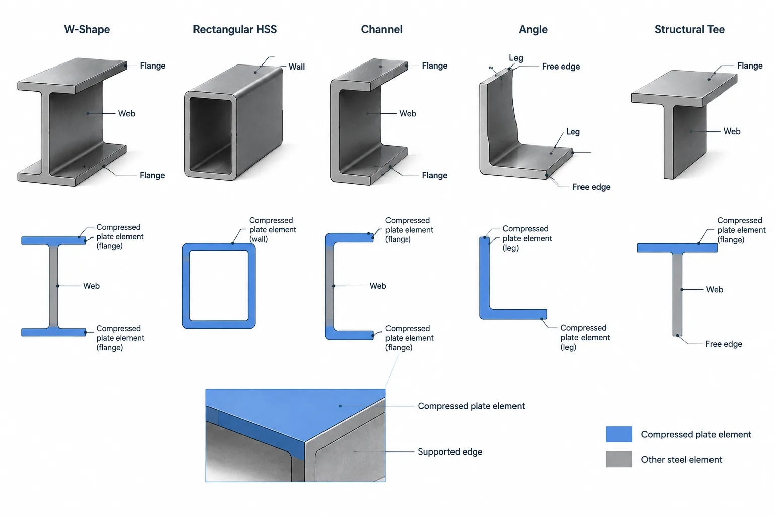
| Channel | Open side direction and attachments on the web or flange toes | Web back, open side, and viewing direction |
| Angle | Connected leg, outstanding leg, and toe direction | Heel, toes, leg lengths, and connection face |
| HSS member | Face-specific holes, slots, plates, or seam coordination | Named faces, local axes, and top orientation |
| Base assembly | Offset column, shear lug, stiffeners, or asymmetric anchor layout | Building grids and column centerlines |
Shape-reference data can confirm section dimensions and properties, but it cannot determine assembly handedness. Handedness comes from the relationship between the section, added material, hole geometry, member direction, and installed location.
A Practical CAD and Modeling Workflow
Establish orientation before adding attachments
Begin with a defined member direction and section rotation. Identify which end is the start, which face is considered top, and how local axes relate to the project coordinates. This prevents connection material from being placed according to an arbitrary screen view.
Model one verified assembly as the master
For a pair of mirrored locations, complete and check one version before creating the other. Confirm its section orientation, setbacks, hole locations, plates, weld-side intent, and end conditions. A partially developed assembly can spread unresolved mistakes when mirrored.
Create the opposite hand deliberately
Use a controlled reflection plane tied to meaningful geometry, such as a grid line, member center plane, or framing centerline. After reflection, inspect the member rather than accepting the CAD operation as proof of correctness. Some annotations, connection components, weld information, and parametric relationships may require separate adjustment.
Assign distinct piece marks when fabrication differs
If two assemblies are mirror images rather than truly identical parts, treating them as one mark can create shop and erection problems. Piece-mark decisions should reflect actual fabrication geometry and the project’s established marking practice. Similar overall dimensions do not make two assemblies identical.
Generate views from a consistent direction
Shop details are easier to compare when paired assemblies use the same viewing convention. If views must face opposite directions, clearly identify that difference. End views are especially valuable because they expose face-specific plates, channel orientation, angle legs, and offsets that may overlap in elevation.
Checks That Catch Mirror-Image Errors
A good review compares geometry rather than relying on visual similarity. Useful checks include:
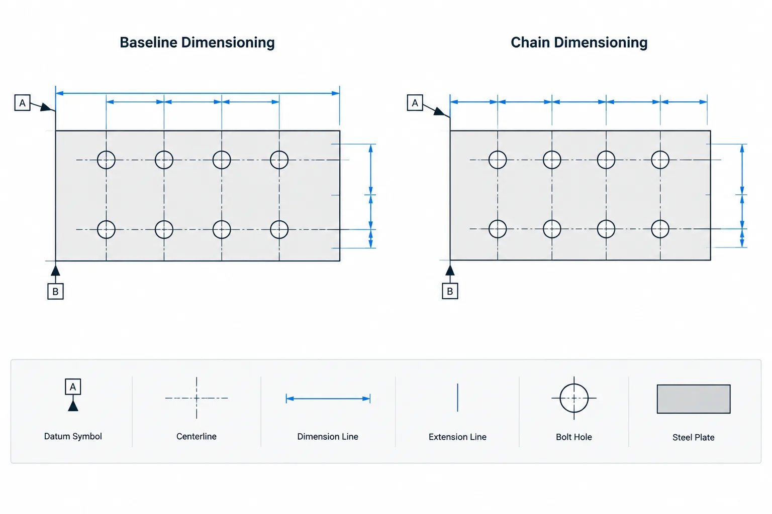
- Compare attachment coordinates relative to the web centerline or member work line.
- Confirm which web face or flange face receives each plate.
- Check angle heels and toes, not just angle bounding boxes.
- Verify channel open-side direction in both model and drawing views.
- Compare top and bottom attachments after any flip or rotation.
- Review start-end relationships for unequal end connections.
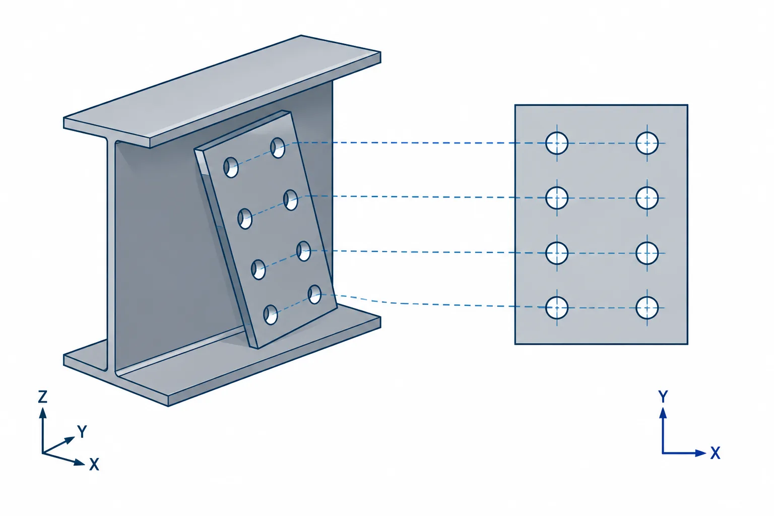
- Check hole patterns for offsets that are easy to overlook.
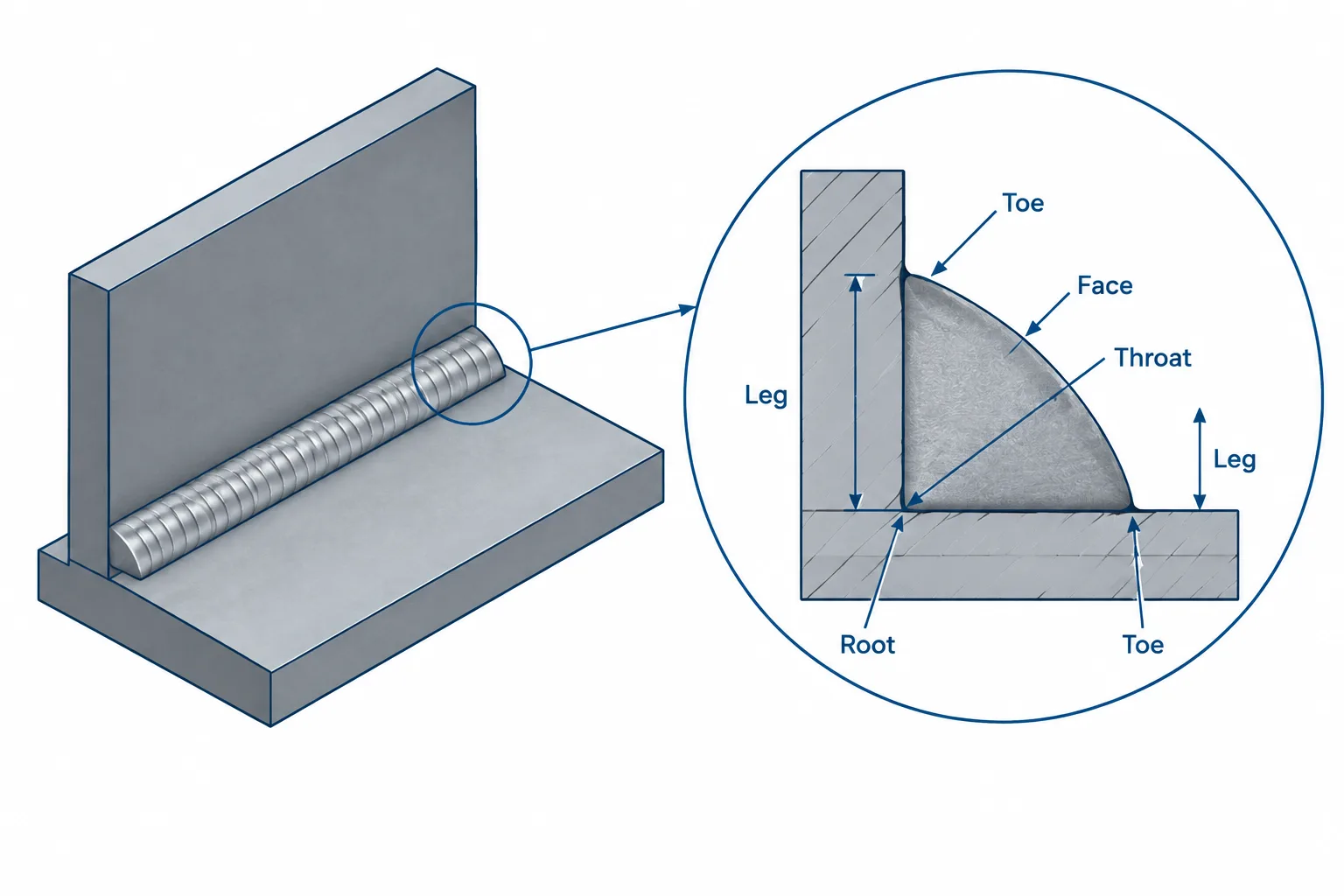
- Confirm that weld locations remain on the intended interfaces.
- Inspect erection clearances and bolt-access sides for each hand.
- Compare piece marks in plans, elevations, shop details, and material lists.
A transparent overlay or model comparison can be useful. Align the main member geometry, then examine where attachments coincide and where they change sides. For coordinate-based checks, a mirrored feature often changes direction relative to one reference axis while retaining its relationships to the others. The applicable result depends on the chosen reflection plane and coordinate system.
Drawing Practices That Improve Clarity
Drawings should communicate the geometry without requiring the shop or field to infer what left and right mean. Consider using:
- Grid labels or directional arrows near the primary view.
- Start-end identification where member direction matters.
- End views for asymmetric sections and attachments.
- Near-side and far-side notation where overlapping material is shown.
- Section cuts through offset or one-sided connections.
- Face labels for HSS or other members with face-specific work.
- Separate details for opposite hands when a single view would be ambiguous.
A note stating that one part is opposite hand may be helpful, but it should supplement complete detailing rather than replace it. Fabrication information should remain traceable through dimensions, views, marks, and material identification.
When Opposite-Hand Assemblies May Not Be Necessary
Not every visually mirrored condition requires a different fabricated member. Some assemblies can be rotated or installed end for end and still satisfy the required geometry. Others use symmetric attachment layouts that remain unchanged under reflection.
Before creating separate hands, compare the complete physical assembly and its installation constraints. Ask whether rotation changes top and bottom, swaps unequal end conditions, alters the connection face, or interferes with access. If no fabrication or installation difference remains, a common assembly may be possible. That conclusion should come from verified geometry and project requirements, not from appearance alone.
Final Coordination Principle
Handedness is fundamentally a reference-control problem. The safest workflow defines member direction, viewing direction, faces, and coordinate references before opposite-hand geometry is created. Distinct marks, clear end views, and deliberate model comparisons then make the difference visible to everyone using the information.
When reviewing handed structural steel assemblies, do not ask only whether the parts look alike. Ask whether the same fabricated object can be moved and rotated into both installed positions without changing any connection, face, elevation, or end relationship. If it cannot, the assemblies must be detailed and tracked as physically different members.