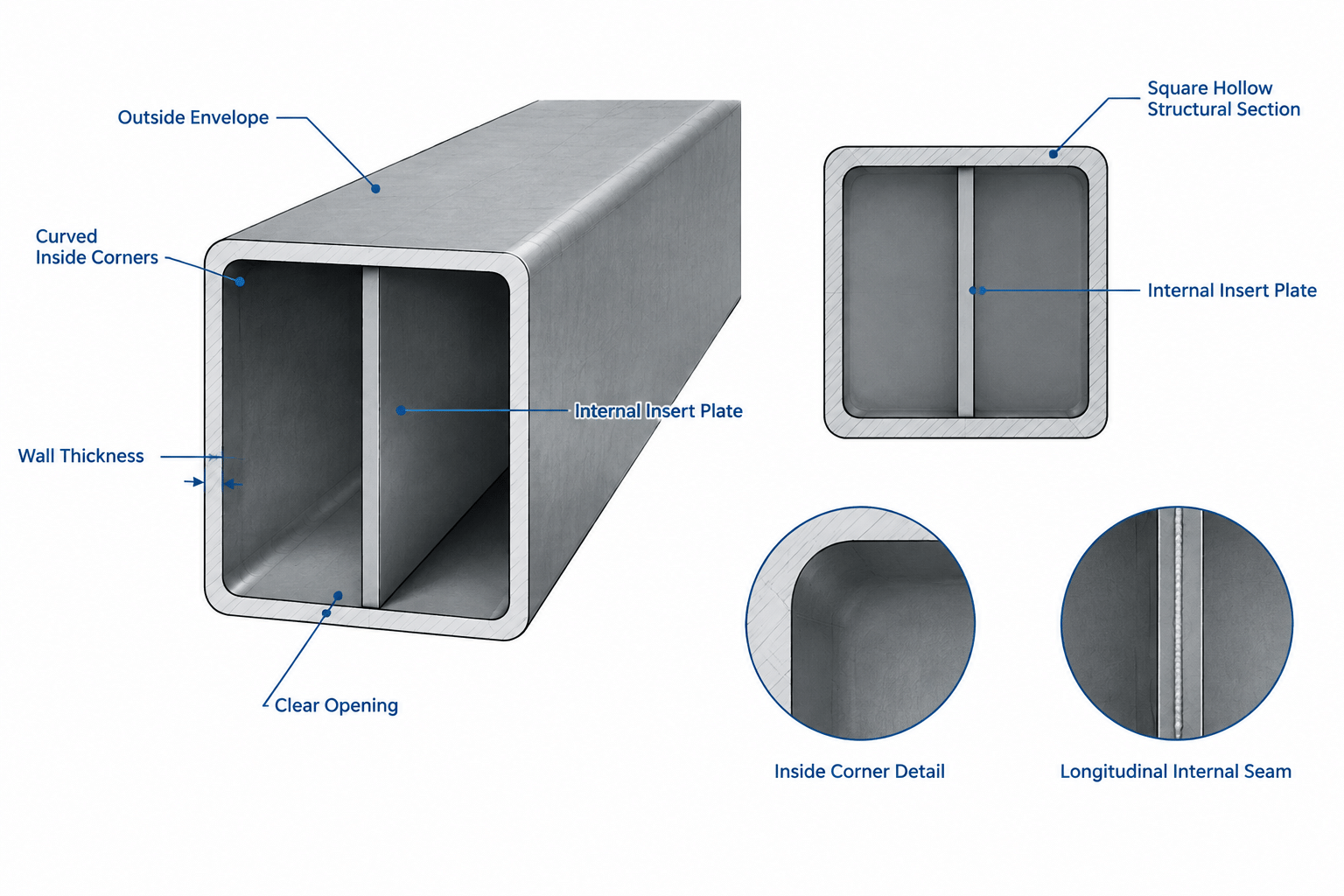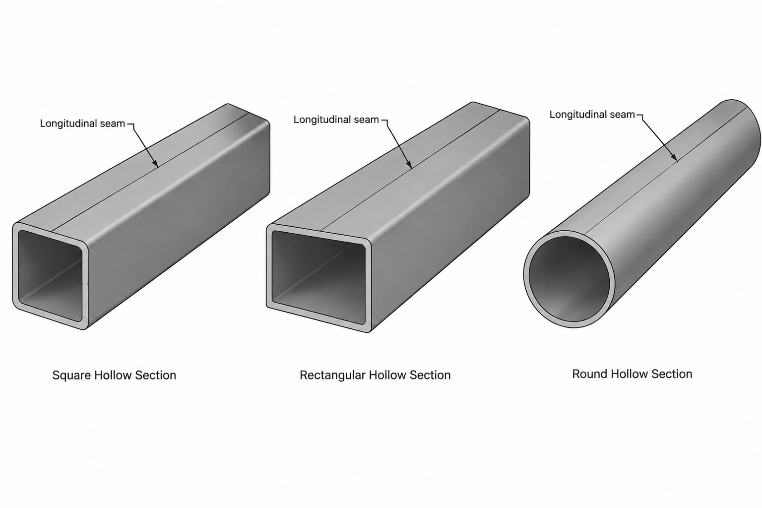
A hollow structural section may look identical on all sides in a simplified drawing, but the manufactured member can include a longitudinal weld seam. That seam is part of the HSS production process and should not be confused with a shop or field weld used to connect the member to another component.
For many ordinary applications, the seam does not require a special orientation on the structural drawings. In other situations, however, its location can affect connection access, through-plates, slots, tapped holes, architectural appearance, and fabrication sequencing. The practical question is not whether every HSS seam must be shown. It is whether the proposed detail depends on the seam being in—or being absent from—a particular location.
What Is the Longitudinal Seam in HSS?
Welded HSS is commonly produced by forming steel into a closed section and joining the longitudinal edges. The resulting seam runs along the member rather than around it. It is therefore different from a circumferential splice weld, an end-plate weld, or the welds connecting an HSS brace to a gusset plate.
The finished seam may be difficult to see on the exterior after manufacturing, coating, or painting. The interior condition can be more important for detailing because an internal weld bead or other local profile variation may interfere with components inserted into the HSS.
Production methods and finishing practices are not identical for every product. A drafter should not assume that the seam is perfectly centered on a selected face, that the interior is completely flush, or that its location can be controlled without coordination. Product documentation, project requirements, and fabricator input are the appropriate sources for those questions.
Why Seam Orientation Can Matter
Most member views do not need to depict the seam merely to make the HSS recognizable. Seam orientation becomes relevant when another feature occupies the same physical region or when the visible face is architecturally important.
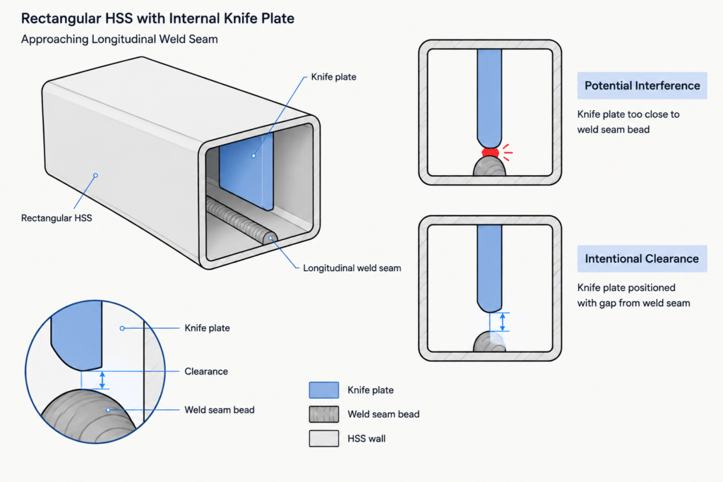
Internal plates and fitted components
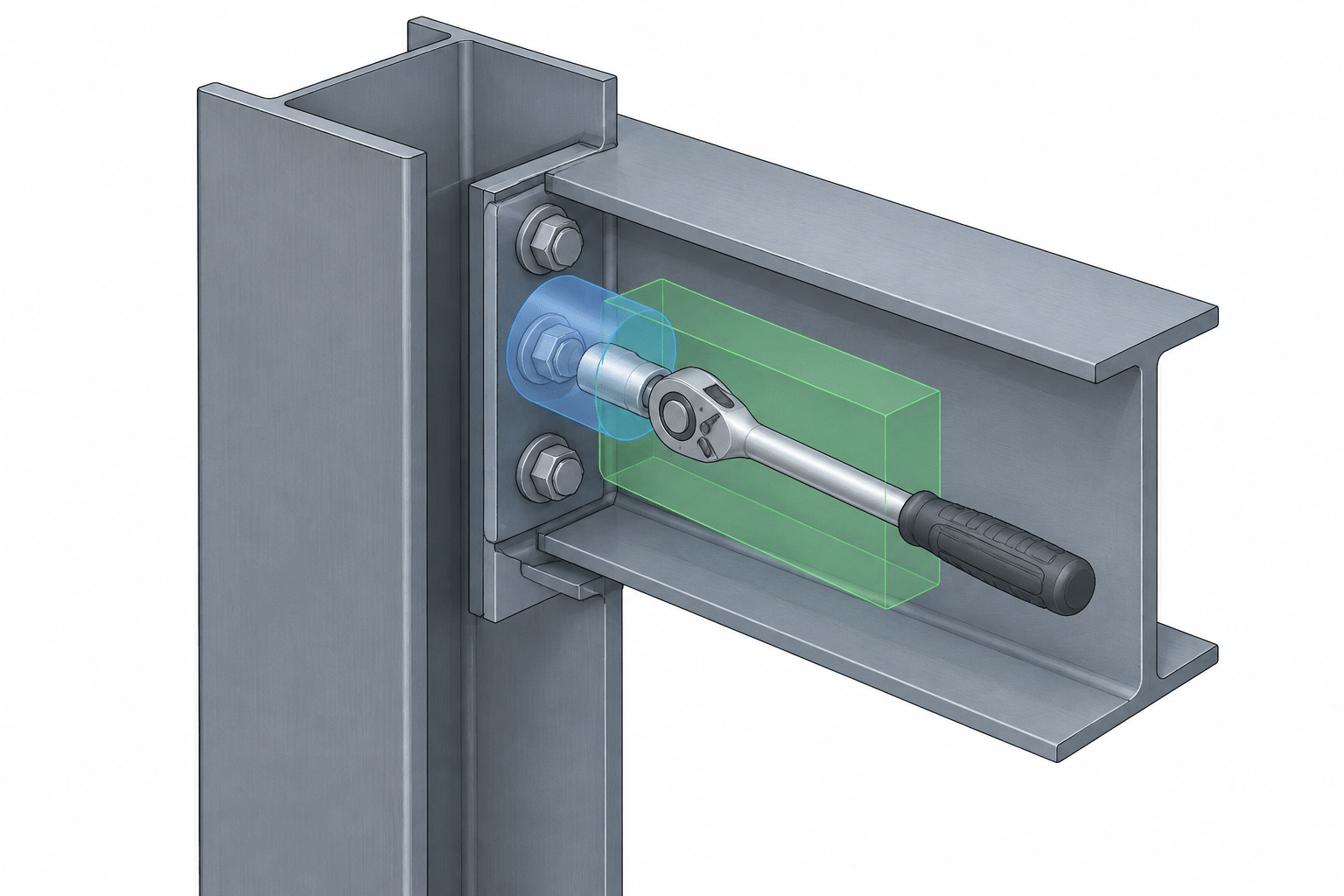
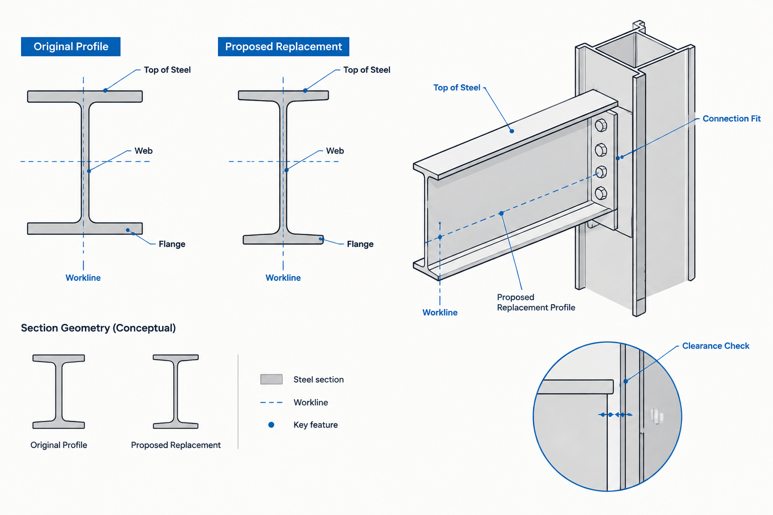
Knife plates, diaphragms, sleeves, end inserts, splice components, and other fitted parts may extend into an HSS. A component modeled to match an idealized clear opening can conflict with an internal seam bead, corner geometry, or normal production variation.
Where fit is critical, the detail should provide an intentional allowance or identify the required preparation. Rotating the member may move the seam away from the inserted plate, but rotation is only a reliable solution when seam location and orientation are actually controlled.
Slots, holes, and face-mounted connections
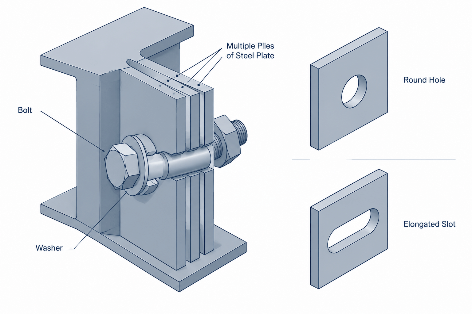
A long slot, line of holes, or face-mounted plate may cross the seam region. This does not automatically make the detail unacceptable, but it can affect drilling, cutting, welding, surface fit, and inspection. The designer and fabricator should review details that rely on a uniformly flat or unobstructed local surface.
Drawings should identify which HSS face receives the connection. If seam position is consequential, that requirement should be stated directly rather than left to the apparent orientation of a generic section symbol.
Through-plates and intersecting cuts
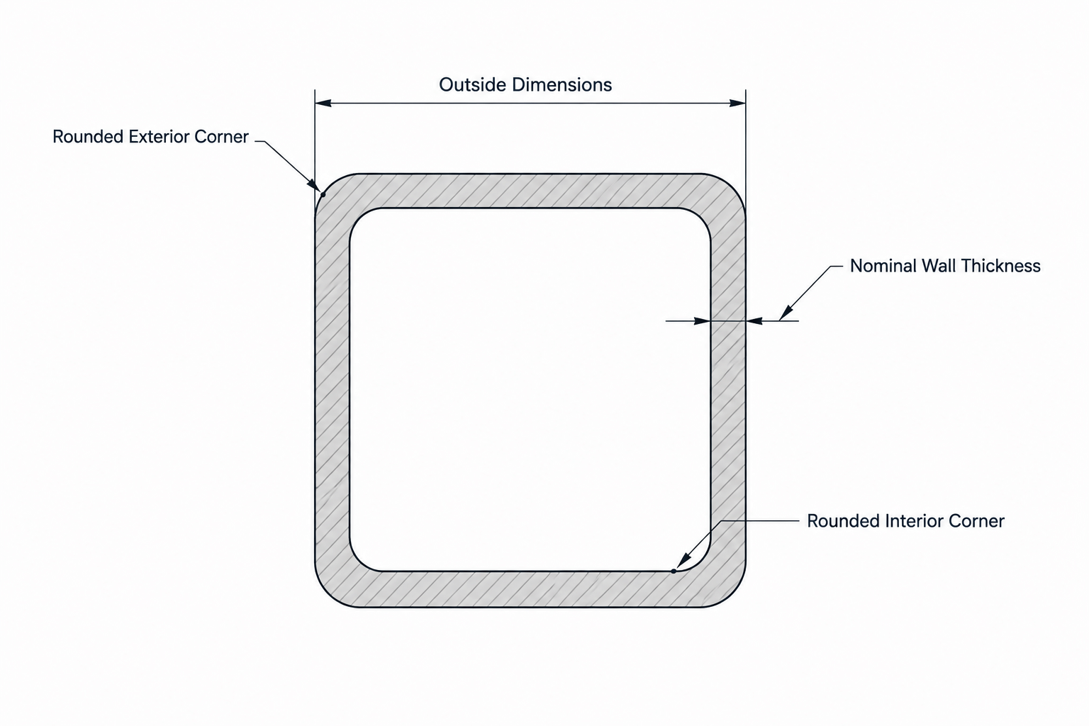
Through-plates and plates passing through slots in opposite walls require coordinated cuts. The relationship among the seam, corner regions, plate thickness, and slot geometry can affect fabrication. A schematic CAD section showing perfectly sharp corners and an invisible seam is not enough to establish fit.
Architecturally exposed surfaces
On exposed steel, the seam region may differ subtly in texture or appearance after finishing. If one face is especially prominent, the project team may prefer another face for the seam. That preference should be coordinated with fabrication and finishing requirements rather than expressed as an assumed manufacturing condition.
Square and Rectangular HSS
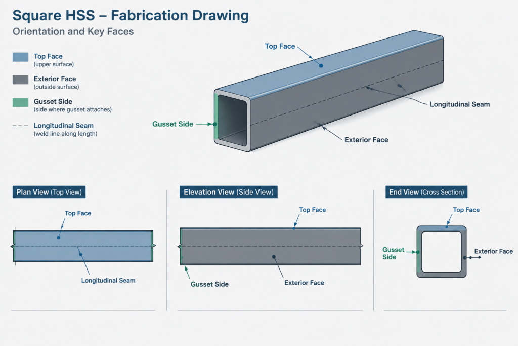
Square and rectangular HSS give the detailer several distinct faces, so orientation can be communicated relative to the building or connection. Examples include seam toward the interior, seam on the underside, seam away from an exposed elevation, or seam on a face without attachments.
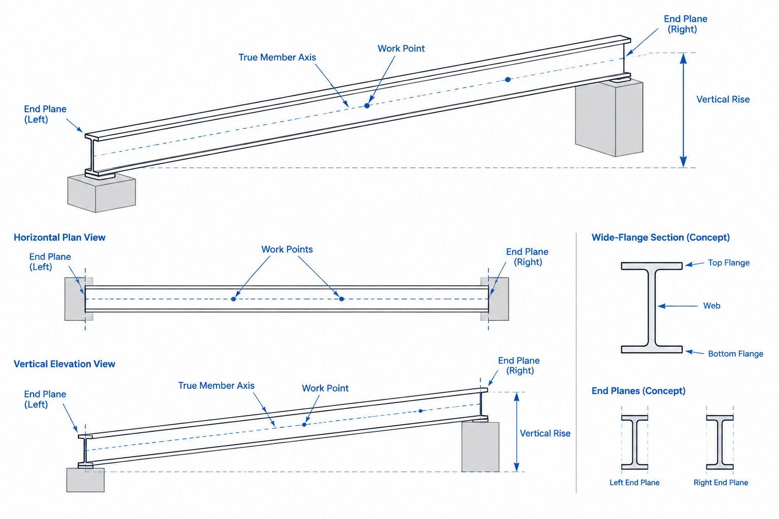
A useful drawing establishes a stable reference for those instructions. Terms such as “top face,” “exterior face,” or “gusset side” are clearer than an isolated note saying “seam down” when the member slopes, rotates, or appears differently in multiple views.
Do not infer the seam face from the HSS designation. The designation describes the section, not its rotational placement within the structure. Likewise, a CAD block with a seam line is only a graphic representation unless the model and fabrication documents preserve that orientation.
Round HSS Requires Different Thinking
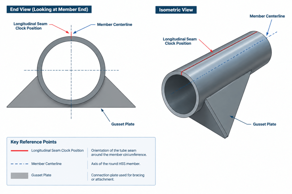
Round HSS has no flange face or rectangular side that naturally establishes rotation. A longitudinal seam may exist, but rotating the member around its axis does not change its overall section outline. As a result, seam orientation can be lost easily between design, modeling, nesting, fabrication, and erection.
If a connection depends on the seam occupying a particular clock position, the drawings need a defined reference. That reference might be tied to a gusset plate, connection centerline, erection mark, or another physical feature. A seam line shown in only one section view may not provide enough information to control the actual member.
When Should the Seam Be Shown?
| Condition | Typical drawing approach |
|---|---|
| Ordinary HSS member with no seam-sensitive feature | The seam can often be omitted from general plans and elevations. |
| Internal plate or sleeve with close fit | Show or note the intended relationship and require fit verification. |
| Connection located near the anticipated seam | Coordinate the seam face or revise the connection to avoid relying on an uncertain location. |
| Architecturally significant exposed face | State the preferred orientation and coordinate finishing expectations. |
| Round HSS requiring rotational control | Define the seam position relative to a physical connection or orientation reference. |
| Seam location is not functionally important | Avoid unnecessary orientation requirements that restrict fabrication without adding value. |
Drawing and Model Practices
If seam orientation matters, communicate it consistently across the drawing set and digital model. Practical methods include:
- Adding a seam line to the relevant section or end view and labeling it clearly.
- Using a member orientation note tied to a named face or connection feature.
- Including the requirement on the shop detail rather than relying solely on a typical detail.
- Checking that mirrored or copied members do not unintentionally reverse the required orientation.
- Preserving rotational information when exchanging models between design and detailing systems.
- Confirming that erection marks distinguish members whose geometry is similar but whose seam orientations differ.
A seam line should use a drafting convention that cannot be mistaken for a hidden edge, centerline, bevel, or shop weld symbol. A nearby text label is usually more reliable than line style alone.
Common Detailing Mistakes
- Treating the seam as a perfectly located geometric line: A nominal CAD location should not be used as a substitute for verified production information.
- Modeling the interior as unobstructed: Inserts can conflict with the seam bead, rounded corners, or dimensional variation.
- Showing a seam without controlling it: A seam drawn on a model face may be interpreted as intentional even if no note requires that orientation.
- Over-specifying ordinary members: Requiring every seam to face the same direction can complicate fabrication while providing no structural or visual benefit.
- Using vague directional notes: “Seam back” or “seam down” can become ambiguous on skewed, sloped, or mirrored members.
- Assuming exterior appearance predicts the interior profile: A smooth outside surface does not prove that a fitted internal component will clear the seam region.
A Practical Review Workflow
Start by identifying every operation that penetrates the HSS wall or places a component inside the section. Review slots, through-plates, sleeves, concealed plates, tapped attachments, access holes, and close-fitting caps. Then check whether any exterior face has special visual or finishing requirements.
If the seam could affect the detail, determine whether the best response is to control orientation, provide clearance, permit local preparation, or redesign the component so it is insensitive to the seam. Discuss production availability and fabrication preferences before turning the assumption into a mandatory drawing note.
Finally, verify that the chosen requirement appears wherever it is needed: sections, member details, piece drawings, model attributes, and orientation diagrams. HSS seam orientation is most successfully handled as a coordination issue. Show it when it matters, define it relative to something unambiguous, and avoid depending on idealized CAD geometry for actual fit.