Structural steel shape CAD blocks can save substantial drafting time, especially when a drawing requires recognizable W-shapes, channels, angles, tees, HSS, or pipe sections. However, a downloaded profile is still reference geometry—not a substitute for verified shape data, project criteria, or fabrication information.
The most reliable workflow treats each block as an imported technical asset. Its units, dimensions, insertion point, geometric detail, and source designation should be checked before the profile becomes part of a drawing or office library. This approach prevents a visually convincing section from quietly introducing scale errors, incorrect member placement, or misleading clearances.
What a steel shape CAD block represents
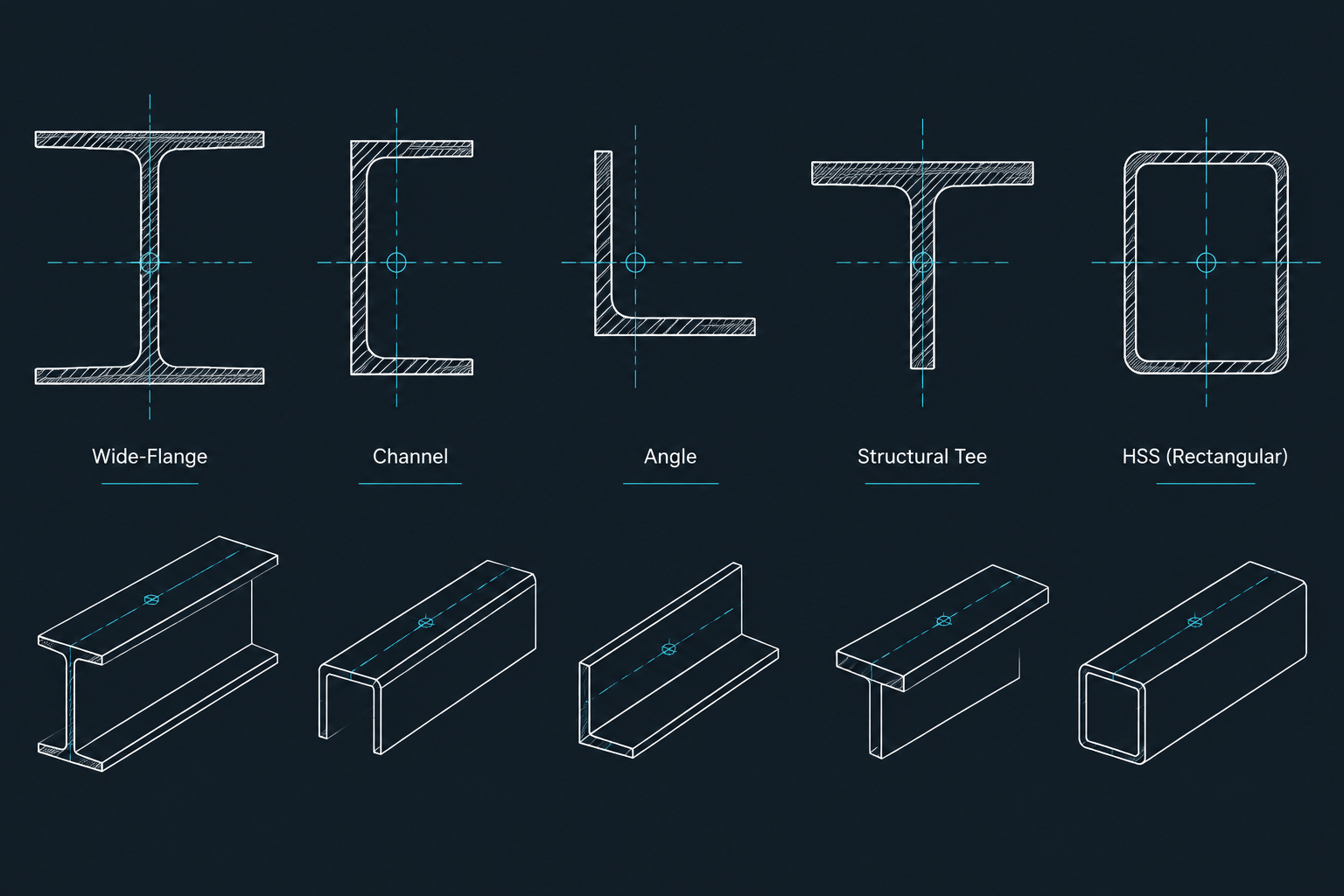
A typical steel shape block represents the cross-sectional outline of a member. Depending on its purpose, the geometry may show:
- Flanges, webs, legs, walls, or stems;
- Rolled fillets or HSS corner curves;
- Centerlines and principal reference axes;
- A designation or descriptive label;
- Closed boundaries suitable for hatching, regions, or extrusion.
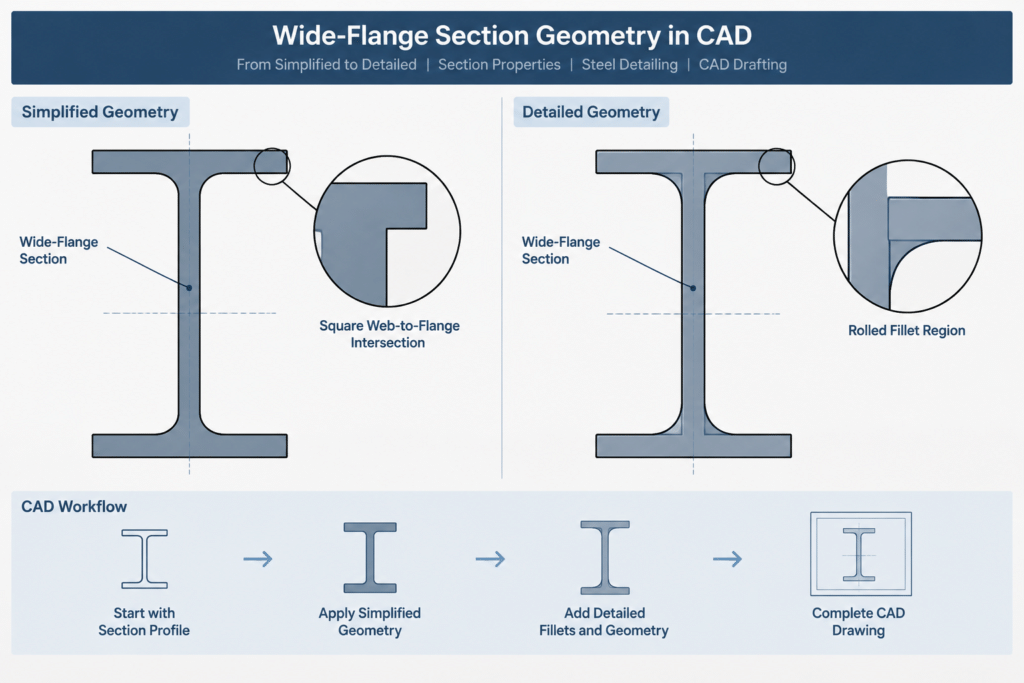
Not every file includes all these elements. A simplified block may use square web-to-flange intersections, while a more detailed profile may include approximate rolled fillets. An HSS block may show only the outside boundary, or it may include both outside and inside corner geometry.
Neither presentation is automatically wrong. The correct level of detail depends on whether the profile is being used for a diagram, a general arrangement drawing, a connection study, a clearance check, or a model intended to support fabrication detailing.
Verify the designation before checking geometry
Begin with the shape name. Confirm that the designation shown in the file, filename, block name, or accompanying note matches the intended shape series. Similar-looking profiles can belong to different families, and a generic I-shaped outline should not automatically be treated as a verified W-shape.
Where a designation includes nominal depth and weight per unit length, those values identify the section but do not define every drafting dimension. The actual depth, flange width, web thickness, flange thickness, and detailing dimensions must come from an appropriate shape reference. Do not reconstruct an entire profile from the designation alone.
Also watch for legacy names, office abbreviations, and user-created block labels. A descriptive name can help organize files, but it does not prove that the geometry corresponds to a current published section.
Check drawing units before scaling anything
Unit mismatch is one of the most common problems with imported CAD content. A block may have been created in inches, feet, millimeters, or unitless drawing units. The host drawing may interpret those units differently during insertion.
Before applying an arbitrary scale factor, measure a recognizable overall dimension and compare it with verified reference data. For a W-shape, overall depth or flange width can provide a useful initial check. For rectangular HSS, compare the outside width and height. For an angle, compare both leg dimensions.
If every checked dimension differs by the same factor, the problem is likely related to units or insertion scale. If some dimensions match while others do not, the geometry itself may be inaccurate, simplified, stretched, or incorrectly labeled. Uniform scaling cannot repair a profile with inconsistent proportions.
A practical unit-check sequence
- Insert the block into a temporary checking file rather than directly into a production drawing.
- Inspect the insertion units and scale values.
- Measure at least two independent dimensions.
- Compare those measurements with a trusted shape reference.
- Correct the unit interpretation or insertion scale only after identifying the cause.
- Save the verified copy with clear unit information.
Understand the insertion point
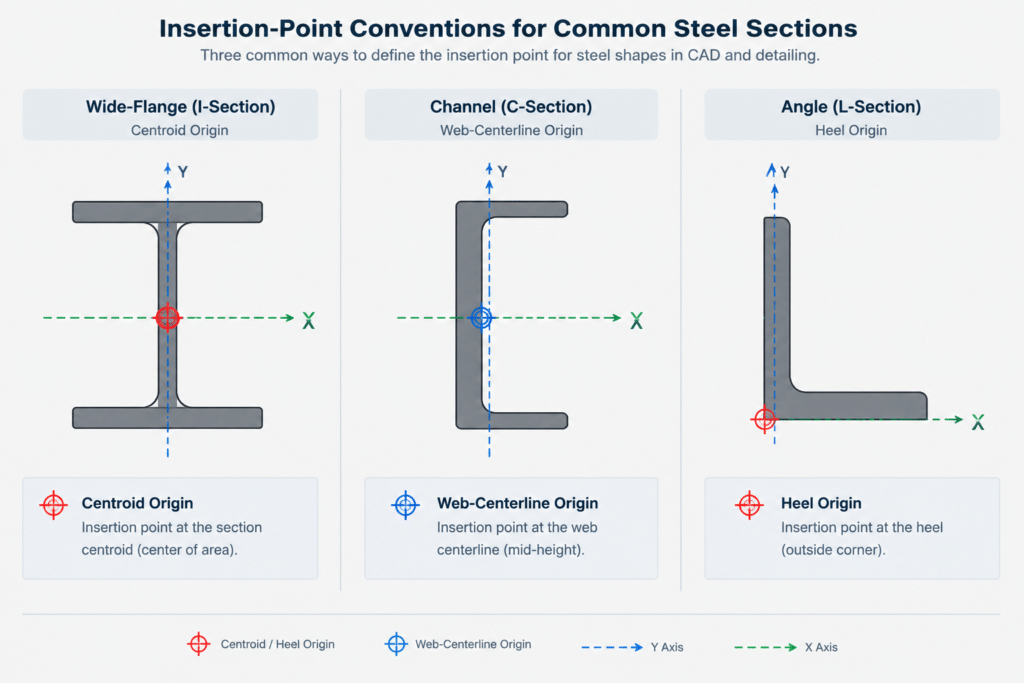
The insertion point controls how efficiently a section can be positioned, rotated, replaced, and aligned. Common origins include the section centroid, geometric center, web centerline, outside corner, heel of an angle, or another convenient drafting point.
These locations are not interchangeable. For doubly symmetric shapes, the centroid and geometric center may coincide. For channels, angles, and tees, the centroid generally does not sit at the visual center of the bounding box. An origin selected merely because it is convenient to draw may therefore be unsuitable for analytical alignment or member replacement.
After insertion, display or construct reference axes and identify where the block origin lies. If the origin is not useful, redefine the block base point in a controlled office copy rather than repeatedly moving individual instances by eye.

| Block origin | Useful for | Potential limitation |
|---|---|---|
| Centroid | Axis alignment, section-property diagrams, analytical references | May not be obvious from the visible outline |
| Web centerline | Beam and column layout using framing centerlines | Does not define elevation or flange-face position by itself |
| Outside corner | Face-based layouts and simple placement | Replacement with another size may shift the member centerline |
| Angle heel | Leg orientation and connected-leg detailing | Is not the centroid or principal-axis intersection |
Decide whether simplified or detailed geometry is appropriate
Simplified profiles are often preferable in small-scale plans and elevations. Excessive fillet and corner detail can increase file size, slow regeneration, and produce crowded plotted linework without improving communication.
Detailed section geometry becomes more important when studying fit near a rolled fillet, locating a plate against an HSS face, illustrating a cope, creating a close-up connection view, or generating a three-dimensional member from the section. Even then, the CAD outline should not be assumed to represent every permissible manufacturing variation.
Use the profile to communicate nominal geometry and design intent. Do not use a perfectly drawn CAD boundary as evidence that real steel will have an exact corner radius, perfectly flat face, or zero dimensional variation.
Keep section outlines separate from connection geometry
A reusable shape block should usually contain only the profile and essential reference information. Connection plates, bolt holes, weld symbols, reinforcing elements, and project notes are better maintained outside the core block or in separate nested components.
This separation reduces the risk of copying project-specific connection information into another detail. It also makes it easier to replace one member size with another without accidentally retaining obsolete holes or plates.
For clearance studies, place connection elements on dedicated layers and identify whether the check is being made to a nominal face, flange edge, web face, fillet boundary, or member centerline. A general statement that an item “clears the beam” is less useful than a drawing that shows which geometric boundary controls.
Use layers and properties consistently
Imported blocks often arrive with unfamiliar layer names, colors, lineweights, or object properties. Review these items before adding the block to an office library. A practical structure may separate:
- Visible section outlines;
- Centerlines and reference axes;
- Hidden or interior boundaries;
- Text and shape designations;
- Construction geometry that should not plot.
Avoid exploding every block merely to force its objects onto current layers. Unnecessary exploding removes the advantages of consistent naming, replacement, and global editing. If standards need to be changed, revise a controlled master block or remap its properties during import.
Do not derive section properties from unverified outlines
CAD software can calculate area, centroid, and moments of area from a closed boundary, but the results are only as reliable as the boundary. Small changes to fillets, corner radii, wall thickness, or flange taper can alter calculated values. Duplicate lines, open loops, and overlapping regions can also produce unexpected results.
Use published section-property data for engineering work unless there is a specific reason to analyze custom geometry. If CAD calculations are used as a quality-control exercise, identify whether the outline is simplified and document any assumptions. A close numerical comparison may help detect a drawing error, but it does not convert an unknown block into an authoritative section database.
Create a controlled verification record
A well-managed library should make it clear which files have been reviewed. The record does not need to be elaborate, but it should identify the shape designation, drawing units, checked dimensions, origin convention, geometry type, and review date. It should also distinguish externally obtained files from office-created geometry.
Consider using a consistent block naming structure that separates the shape family and designation from optional attributes such as simplified or detailed geometry. Avoid placing project approval language in a generic library name. Verification for library use is not the same as approval for a particular structure or connection.
Final CAD block review checklist
- Confirm the shape family and full designation.
- Identify the source drawing units and host drawing units.
- Measure more than one dimension against verified data.
- Locate the insertion point and reference axes.
- Determine whether fillets and corners are simplified or detailed.
- Check that closed outlines are actually closed when regions or extrusions are required.
- Remove unrelated connection geometry and project-specific notes.
- Review layers, line types, text styles, and plotting behavior.
- Do not infer engineering properties or connection capacity from the block alone.
- Retain a clean master and perform project edits in a separate file.
Structural steel shape CAD blocks are most valuable when they are predictable. A verified unit system, meaningful origin, appropriate detail level, and controlled layer structure allow the same profile to support diagrams, sections, layouts, and connection studies without becoming a hidden source of drafting error. The block should accelerate the work while verified references, project drawings, and responsible technical review continue to control the result.

