W-shape steel tables contain much more than a list of beam sizes. They connect a member’s designation to its geometry, mass, structural section properties, and drafting information. Knowing how to read the table helps engineers, detailers, fabricators, estimators, and CAD users select the correct reference data without confusing a nominal designation with an exact measured dimension.
This guide explains the common information found on American wide-flange, or W-shape, reference pages. It is intended to help you navigate a shape database and prepare drawings or design calculations. It does not replace project-specific engineering review, design criteria, connection design, or the controlling project documents.
What the W-shape designation means
A designation such as W24x84 contains two primary pieces of information:
- W identifies the general wide-flange shape family.
- The first number is the nominal depth designation, expressed in inches.
- The number after the “x” is the nominal weight, expressed in pounds per linear foot.
The designation is a convenient identification system, not a complete dimensional description. The nominal depth is not necessarily the exact measured distance from the outside of one flange to the outside of the other. Likewise, the listed weight is a shape designation value and should not be treated as a substitute for the project’s material takeoff or fabrication information.
Two W-shapes can have similar nominal depths but different flange widths, thicknesses, and section properties. Conversely, shapes with different nominal depths may sometimes be considered for the same general framing role. The designation is therefore the starting point for finding a shape, not the final basis for comparing performance.
Nominal dimensions versus tabulated dimensions
Shape tables commonly include values such as overall depth, flange width, web thickness, and flange thickness. These values describe the rolled geometry represented by the reference data. They are more useful for detailing and coordination than the nominal designation alone.
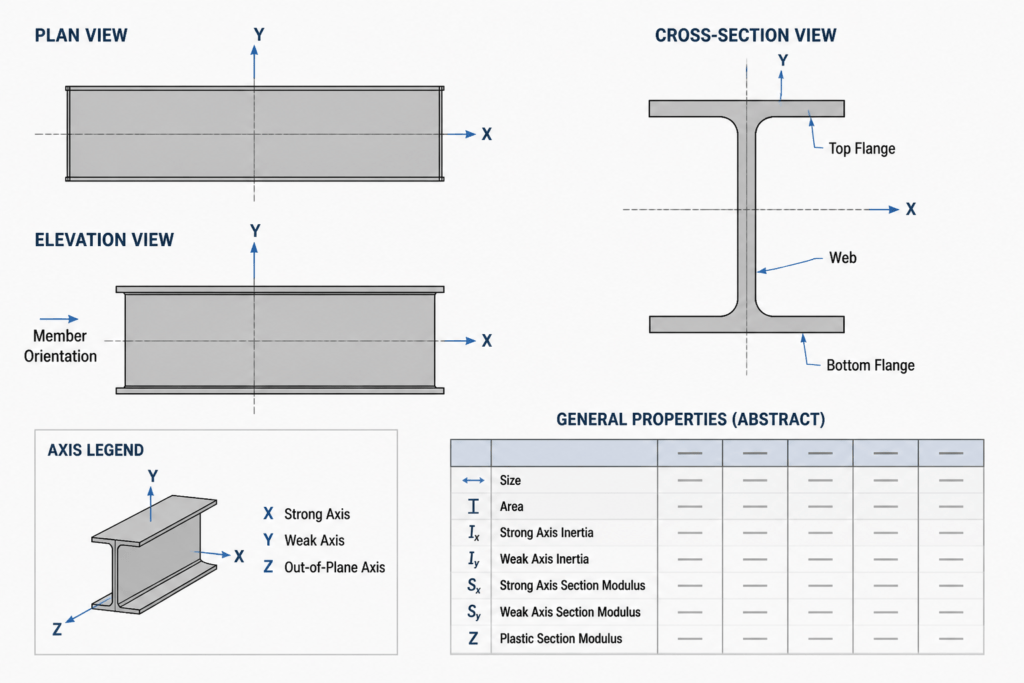
Overall depth
The tabulated overall depth represents the section’s overall vertical dimension in the principal bending orientation. It can differ from the rounded depth implied by the designation. This distinction matters when checking framing elevations, floor-to-floor clearances, equipment interfaces, and the available space for connection components.
Flange width and thickness
Flange width affects the footprint of the member and can influence framing alignment, bolt access, bearing details, and interference with adjacent members. Flange thickness is relevant to connection detailing, local resistance checks, weld sizing, and the physical location of flange surfaces.
Web thickness
The web carries a major portion of the section’s shear-related behavior and separates the flanges. In drawings, the web thickness also affects the appearance and constructability of web connections, stiffeners, shear plates, and penetrations. A web that is visually represented with a generic line should still be coordinated against the actual tabulated geometry when a connection or opening depends on it.
How to interpret the principal axes
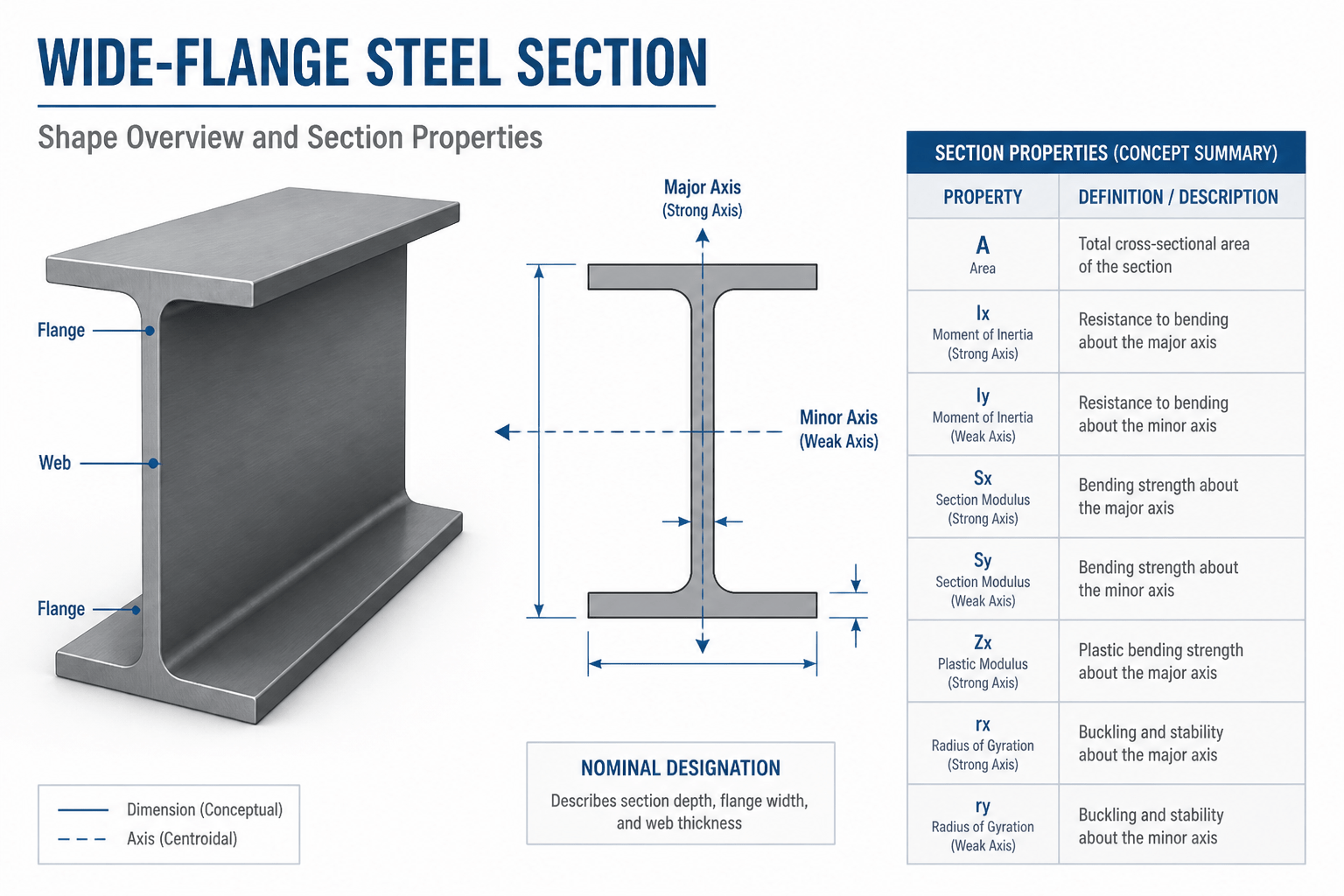
Most W-shapes are symmetric about their major and minor geometric axes. The x-axis is normally associated with the major, or strong, axis, while the y-axis is associated with the minor, or weak, axis. Reference tables use these axes consistently, but the orientation must still be checked when a member is rotated or modeled in an unusual position.
For a conventional beam standing with its web vertical, bending about the x-axis generally involves the section’s larger depth-related properties. Bending about the y-axis involves the flange-to-flange distribution across the narrower direction. In a CAD model, a rotated member may look correct while its analytical orientation or local axes are wrong, so the shape direction should be verified in both the model and the design software.
Axis labels are especially important when transferring data between a shape database, structural analysis software, and a drawing package. A correct shape with an incorrect local-axis orientation can lead to misleading reactions, member annotations, or connection geometry.
Section properties you will commonly see
Section-property tables use abbreviated symbols. The exact presentation varies by database, but the following groups are common:
| Property group | What it describes | Why it matters in practice |
|---|---|---|
| Area, A | Cross-sectional area | Used in axial behavior, mass calculations, and some stability checks |
| Moment of inertia, Ix and Iy | Resistance of the area to bending about each principal axis | Used in stiffness and deflection-related calculations |
| Elastic section modulus, Sx and Sy | Area distribution relative to the extreme fibers | Used in elastic bending calculations |
| Plastic section modulus, Zx and Zy | Area distribution used in plastic bending concepts | Used where the applicable design method permits or requires plastic analysis |
| Radius of gyration, rx and ry | Area distribution expressed as a length property | Useful in slenderness and stability-related calculations |
| Torsional and warping properties | Resistance associated with twisting and nonuniform torsion | Relevant for members affected by torsion, lateral restraint, or open-section behavior |
Do not compare a single property in isolation. A shape with a larger strong-axis inertia may not be the best option when weak-axis stability, connection geometry, torsion, weight, or clearance controls. Section properties support engineering decisions; they do not make the decision by themselves.
Reading the table for CAD and detailing work
When using a W-shape reference page to create a drawing or model, begin by confirming the complete designation. Then check the dimensional fields needed for the task rather than relying on a schematic symbol or nominal depth.
- For framing plans: verify the member centerline, orientation, framing elevation, and flange alignment.
- For elevations and sections: use the tabulated depth and flange dimensions when clearances or interfaces are important.
- For connection drawings: confirm web and flange geometry before placing plates, angles, bolts, welds, stiffeners, or access clearances.
- For material schedules: preserve the exact shape designation and avoid shortening it in a way that could identify a different section.
- For 3D models: check the local coordinate system, insertion point, rotation, and end treatment after importing or creating the profile.
A simplified CAD representation is often appropriate for general arrangement drawings. A more detailed representation may be necessary for fabrication, connection coordination, clash detection, or shop-level documentation. The required level of detail depends on the drawing purpose and project workflow.
Common mistakes when using W-shape data
Using the designation as an exact dimension
The nominal depth should not be used for a tight clearance check when the table provides a more precise dimensional value. Always use the appropriate tabulated dimension and account for finishes, connection components, tolerances, and adjacent construction where applicable.
Confusing weight with total member weight
The weight portion of the designation is a linear weight reference. Total member weight depends on the member length and may also include coping, holes, plates, weld metal, trims, and other attached components. Estimating and fabrication workflows should use the data required by the project’s quantity procedure.
Mixing unit systems
Some tables present geometry in inches and section properties in combinations of inches, pounds, or other customary units. Before transferring values into software, confirm the unit label for every field. A unit mismatch can produce an apparently reasonable but incorrect result.
Ignoring the shape orientation
A W-shape is not interchangeable in every orientation. Turning the member changes its relation to the major and minor axes and can affect framing, stability, connection access, and architectural clearances.
A practical checklist
Before using a W-shape table entry in a drawing, model, or calculation, confirm the following:
- The complete designation matches the intended shape.
- The table’s units are understood.
- The actual tabulated dimensions, not only the nominal depth, are used for critical coordination.
- The major and minor axes are correctly oriented.
- The selected section properties correspond to the required analysis method.
- The reference data is consistent with the project’s approved material and design basis.
- Any connection, stability, fire, fatigue, or constructability issue is reviewed by the responsible project team.
Once these checks become routine, a steel-shape database becomes more than a lookup tool. It becomes a reliable bridge between structural terminology, engineering calculations, CAD geometry, and clear project documentation.