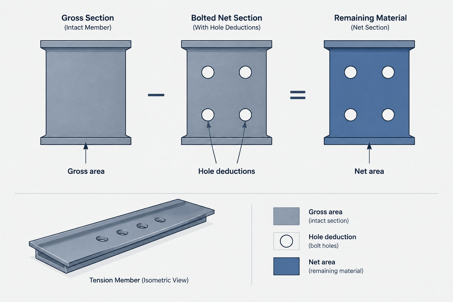
Area appears to be one of the simplest properties in a structural steel table, but the published value does not describe every cross section that may control a connected member. Shape databases generally report the gross cross-sectional area of the rolled or formed shape. Bolt holes, slots, copes, and other connection-related material removal must be evaluated separately.
The distinction between gross area and net area is especially important in tension members. It also affects material takeoffs, connection calculations, and the way a drafter represents modified sections. Understanding which area is being used helps prevent a common mistake: treating a tabulated section property as though it already accounts for project-specific connection geometry.
What Is Gross Area?
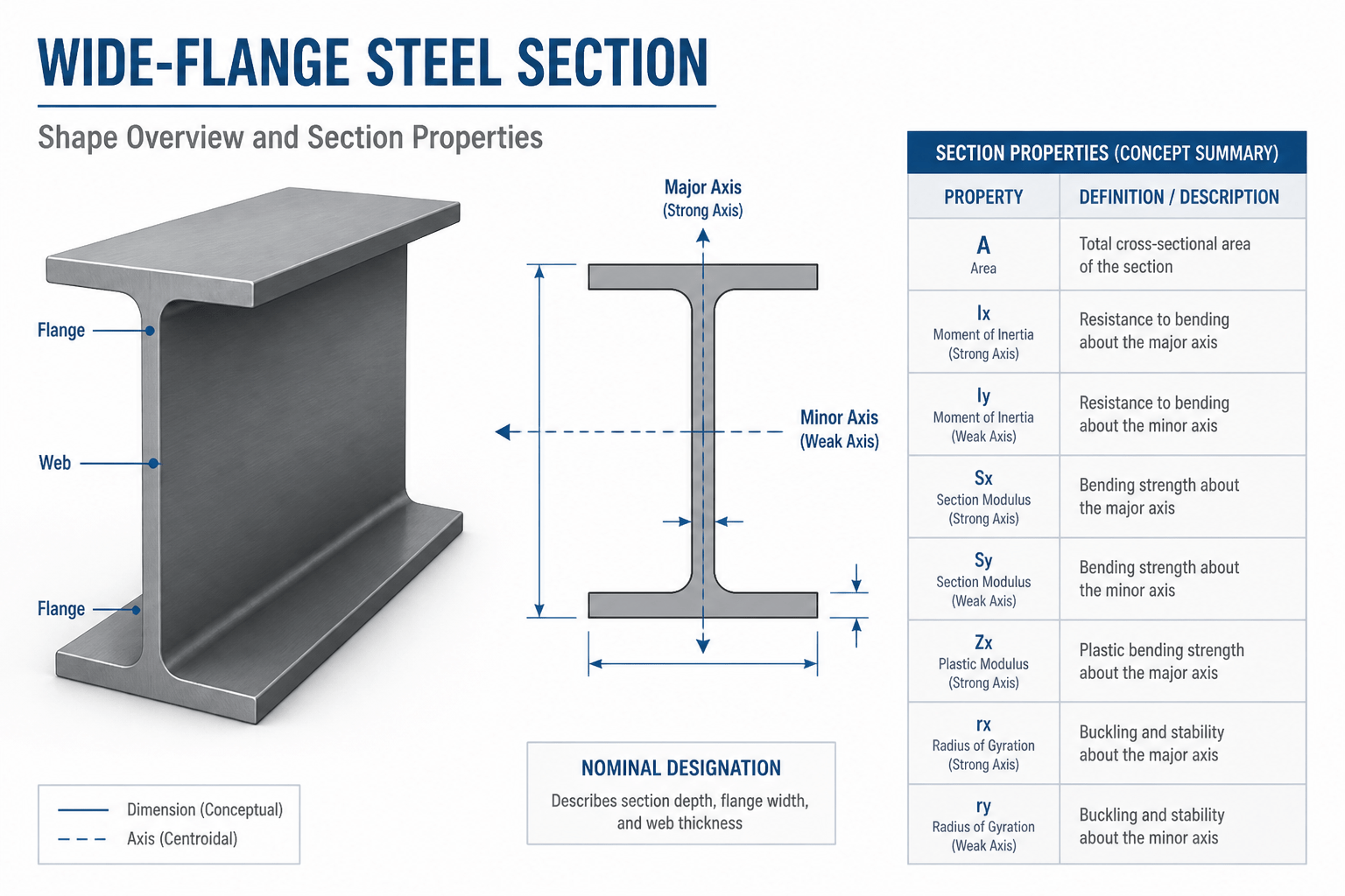
Gross area, commonly written as Ag, is the area of the complete cross section before deductions for connection holes or other local removals. For a rolled shape, this is the section area associated with the published shape designation and weight per unit length.
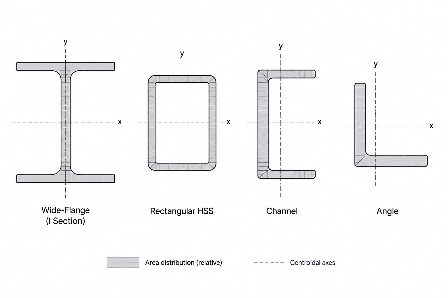
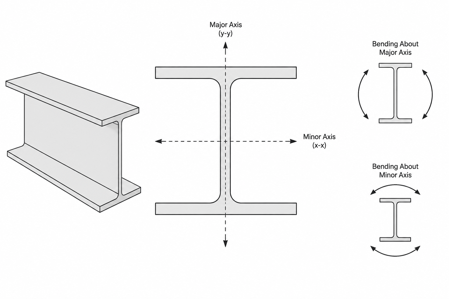
A steel shape table may list area alongside depth, flange width, web thickness, moments of inertia, section moduli, and other properties. That area represents the standard shape, not a beam, brace, angle, or tee after fabrication.
Gross area is relevant to several practical tasks:
- Identifying and comparing standard steel shapes
- Relating section area to nominal weight per unit length
- Evaluating limit states associated with the unperforated section
- Creating preliminary material estimates
- Checking whether a CAD profile represents the intended shape
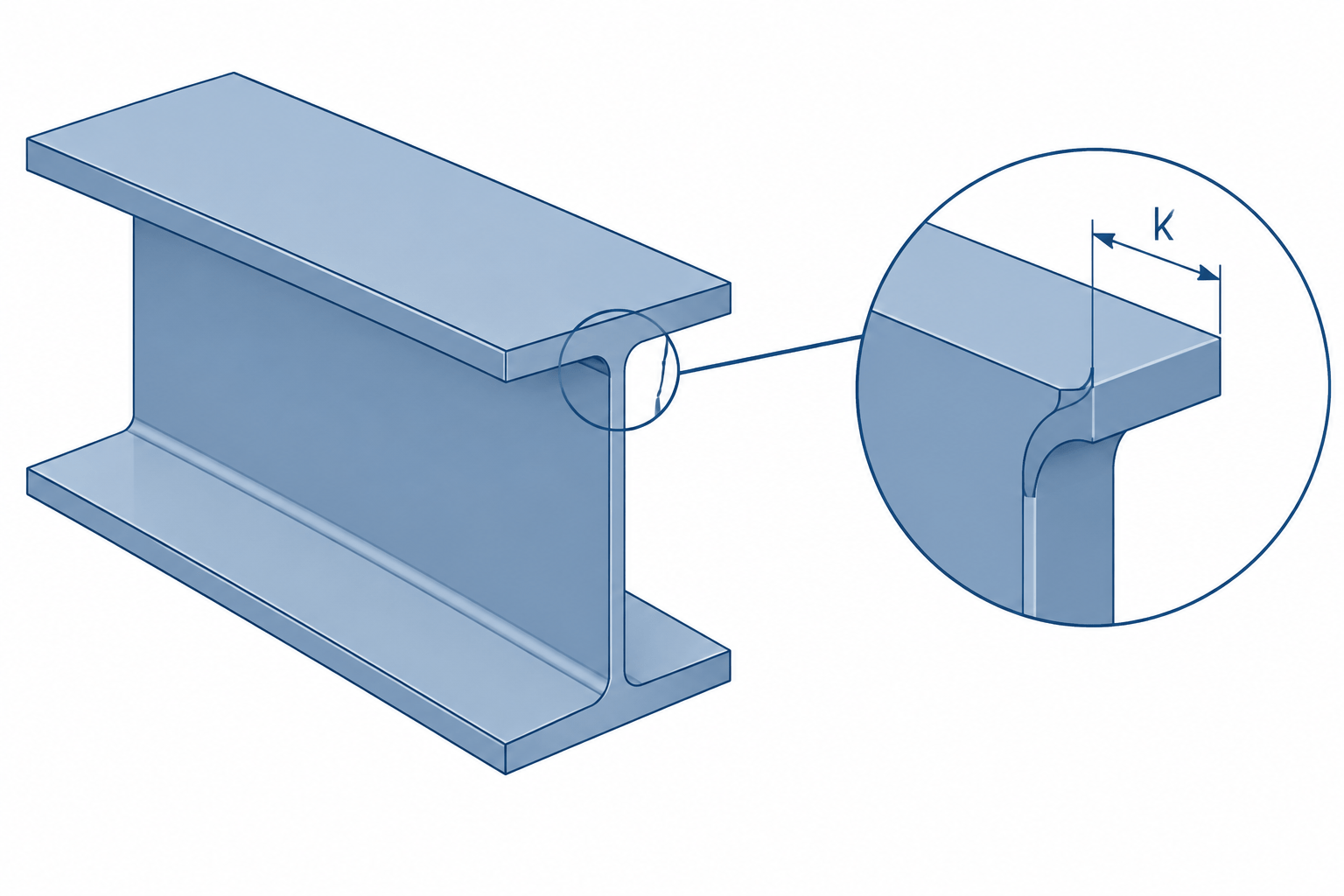
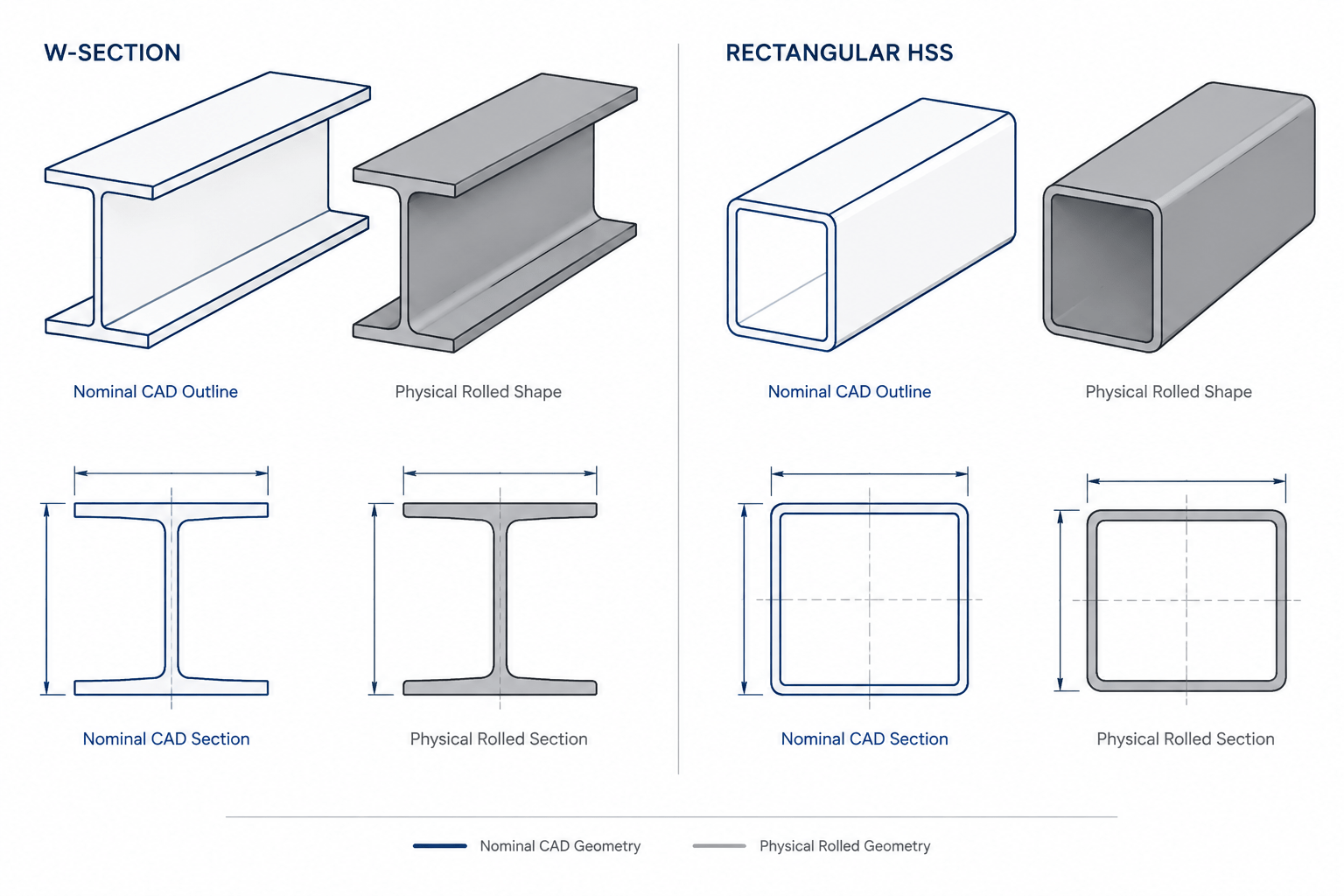
Published gross area should normally be taken from a reliable shape database or applicable reference rather than reconstructed from simplified rectangles. Rolled W-shapes, channels, angles, tees, and HP shapes include fillets and other geometry that a basic outline may omit.
What Is Net Area?
Net area, commonly written as An, is the remaining cross-sectional area along a selected failure path after applicable deductions. In a bolted tension member, the deductions commonly correspond to holes or slots crossed by that path.
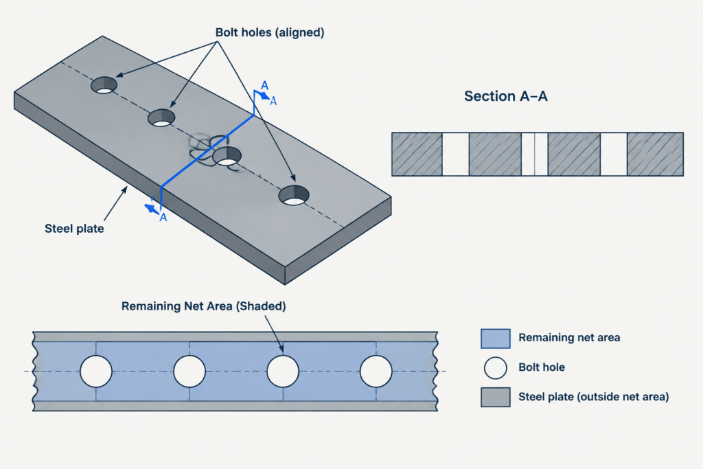
For a simple straight path through a flat element of uniform thickness, the underlying concept may be expressed as:
An = Ag − Σ(dht)
In this simplified expression, dh represents the applicable deduction width for a hole and t represents the element thickness. The deduction used in design is not necessarily the nominal bolt diameter or the dimension drawn for visualization. It must be established from the governing design and detailing requirements.
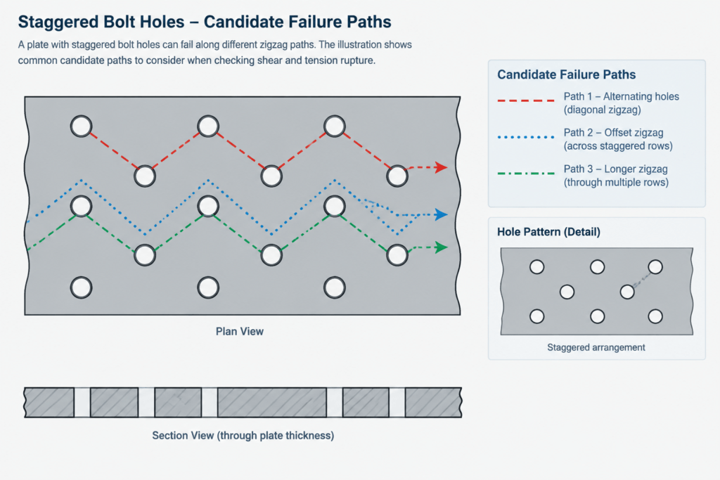
Real connections may be more complicated than a straight row of holes. Potential net-section paths can cross different parts of a shape, pass through staggered holes, or involve connected elements with different thicknesses. The controlling path is not always the visually shortest line.
Gross, Net, and Effective Net Area
| Term | Meaning | Typical source |
|---|---|---|
| Gross area, Ag | Area of the complete, unmodified cross section | Published shape table or verified section data |
| Net area, An | Area remaining along a selected path after applicable deductions | Calculated from connection geometry |
| Effective net area, Ae | Net area adjusted for nonuniform stress transfer, where applicable | Calculated using the governing design provisions |
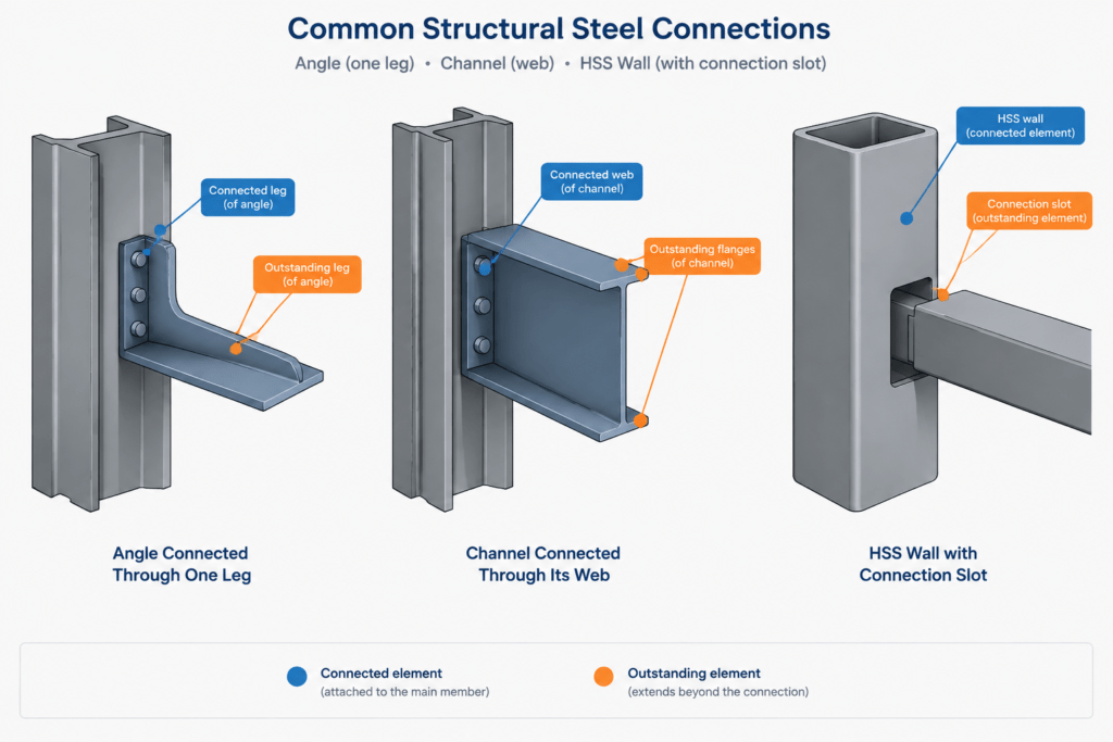
Effective net area is needed because a connection may not transfer force uniformly into every part of the cross section. When only part of a member is connected, portions farther from the connection can lag in developing tensile stress. This behavior is commonly described as shear lag.
As a result, effective net area may be less than net area. A welded member can also be affected by shear lag even when it has no bolt holes. The absence of a hole deduction does not automatically mean that the entire gross area is fully effective for every connection configuration.
How Shape Type Changes the Net-Section Problem
W-Shapes and Structural Tees
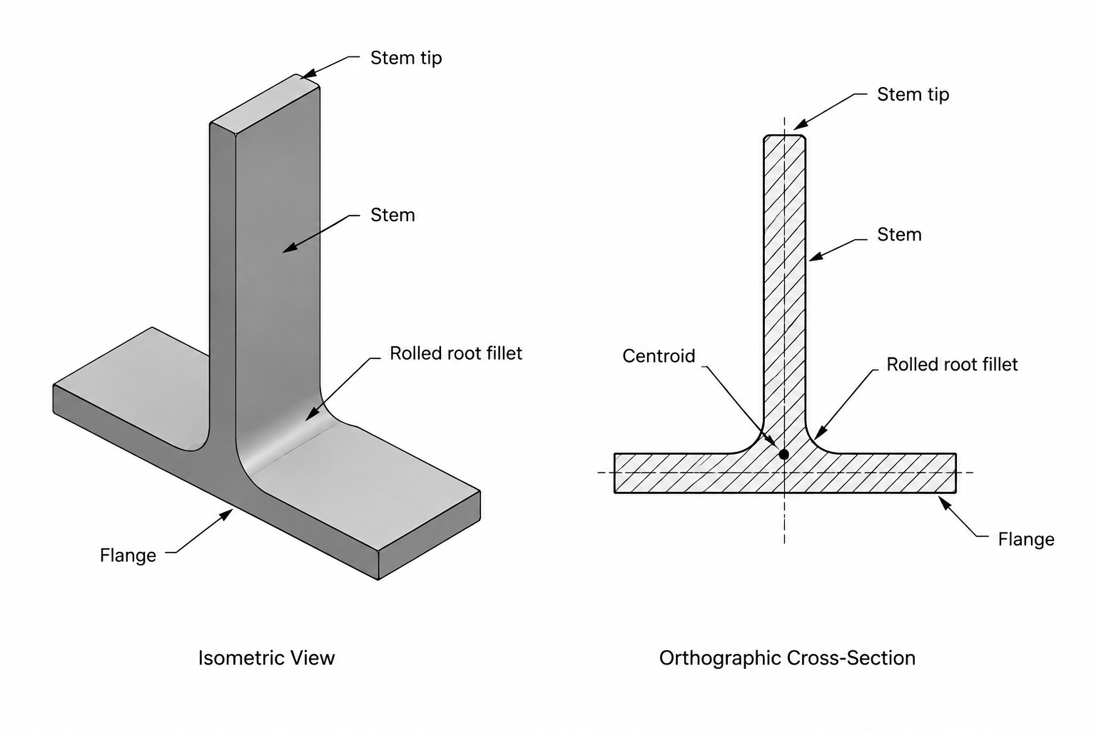
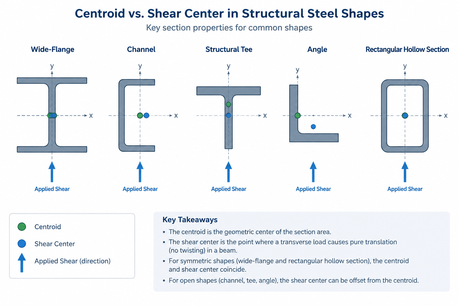
A W-shape may be connected through its flanges, web, or a combination of both. The connected elements and the location of holes influence the potential net path and the degree of stress transfer into the rest of the section. A tee has similar concerns, but its unsymmetrical geometry can make connection eccentricity and outstanding elements especially important.
Channels
Channels are frequently connected through the web, leaving the flanges outstanding from the connection plane. The gross area remains available in a shape table, but net-area deductions and effective-area considerations depend on how the channel is actually attached. Single-channel connections can also introduce eccentricity that is not visible from area alone.
Angles
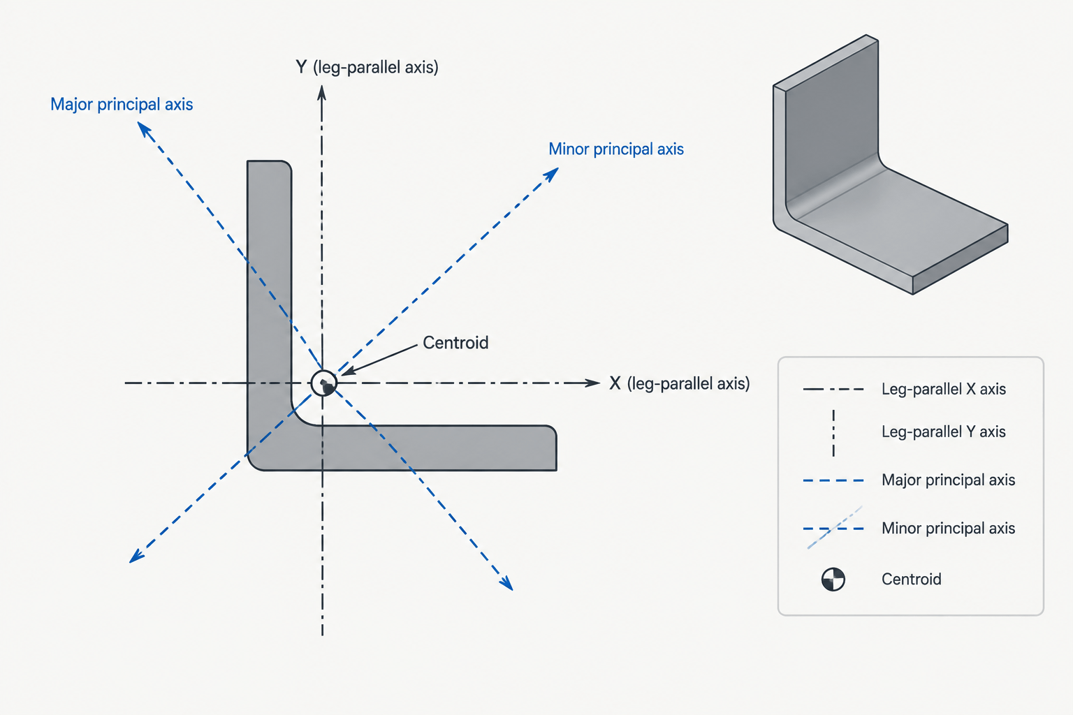
An angle connected through one leg is a classic example of why net area and effective net area are different concepts. Holes reduce the physical section, while the unconnected leg may not receive tensile stress as uniformly as the connected leg. Double-angle arrangements require attention to the actual connection and member configuration rather than assumptions based only on the combined gross area.
HSS Members
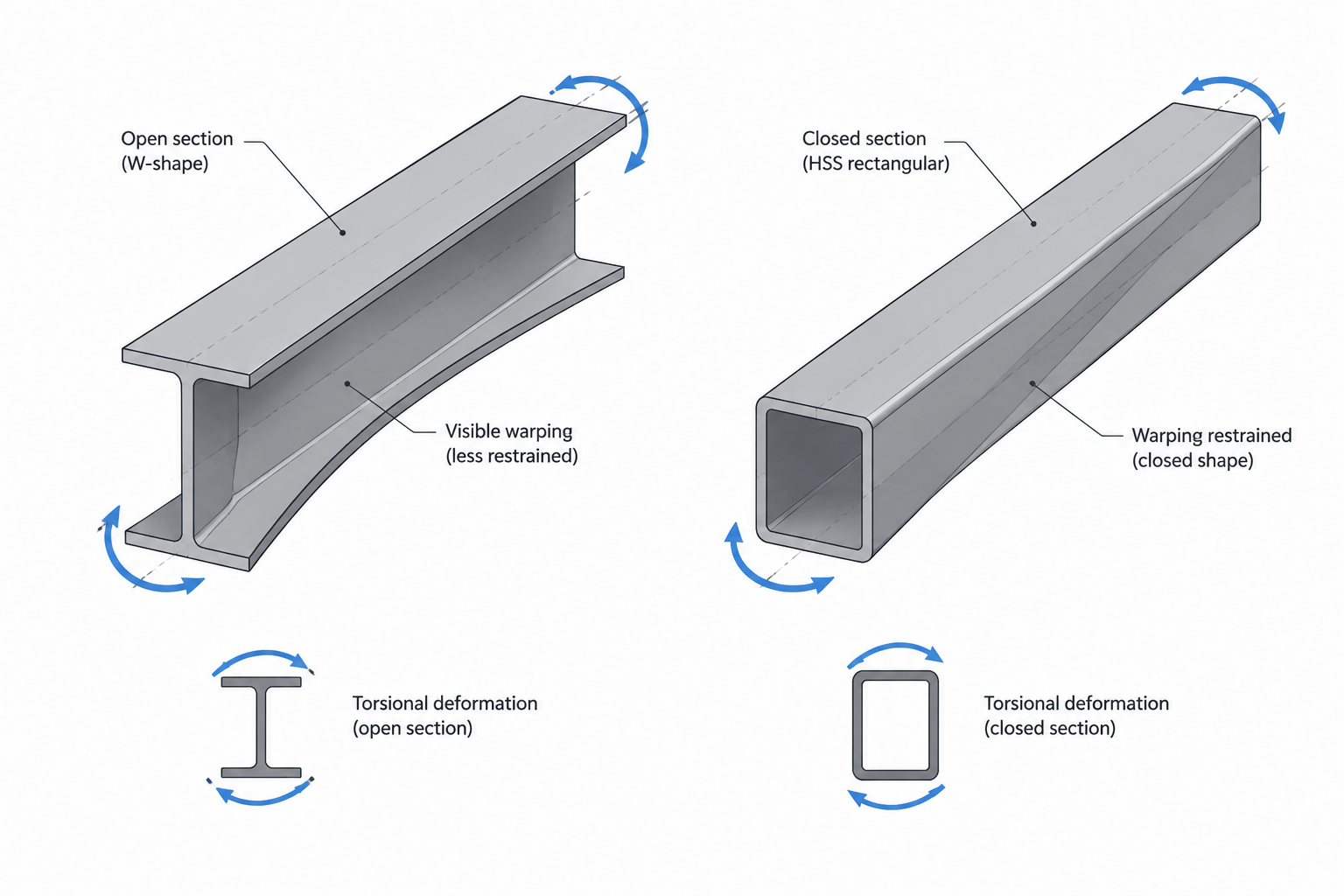
For hollow structural sections, connection details may include through-bolts, slots, gusset plates, knife plates, or locally cut walls. The relevant net section depends on which walls are penetrated and how force enters the tube. Flattening an HSS perimeter into a simple plate model can be useful for visualization, but it does not replace a connection-specific engineering evaluation.
Plates and Bars
Plates often provide the clearest introduction to net-section paths because their width and thickness are readily visible. Even so, staggered holes, edge geometry, multiple bolt lines, and changing plate width can create several plausible paths. Each relevant path must be identified before selecting a controlling net area.
Staggered Holes and Competing Paths
When holes are staggered rather than aligned across the member, a potential failure path may travel diagonally between them. Design methods can recognize that a diagonal path retains material compared with a direct transverse cut. The resulting calculation depends on longitudinal spacing, transverse spacing, hole deductions, thickness, and the path being examined.
A useful detailing practice is to sketch each plausible path directly on the connection view. Label the holes crossed by the path and note any staggered segments. This makes the calculation easier to review and helps identify paths that might be missed when working only from a bolt schedule.
Net-section rupture should also not be confused with block shear. Block shear involves a combined path around a group of connected material, with portions generally associated with shear and tension. It is a separate connection limit state and cannot be checked merely by finding the smallest transverse net area.
Why CAD Area Commands Can Be Misleading
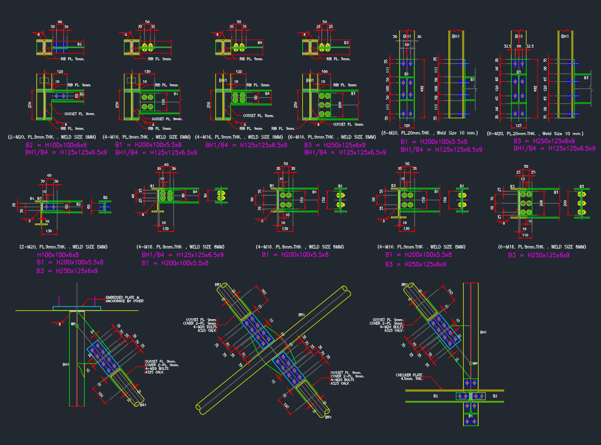
A closed CAD polyline can return an area, but that result is only as accurate as the geometry used to create it. A schematic W-shape drawn from rectangles may omit rolled fillets. A hole symbol may show the nominal bolt size rather than the deduction required for calculation. Hidden holes may also be absent from a particular view.
CAD is valuable for understanding connection geometry, locating section cuts, and checking possible failure paths. It should not silently become the source of design assumptions. Keep the following items distinct:
- The published gross area of the selected shape
- The modeled profile area used for drafting or visualization
- The fabricated hole or slot geometry shown on shop drawings
- The deduction dimensions required by the governing design method
- The effective area determined from the connection configuration
If an area is extracted from CAD, record which outline, section plane, layer, and hole representation produced it. This is particularly useful when revisions change bolt patterns or member end details.
A Practical Review Workflow
- Confirm the member designation. Verify that the shape, plate thickness, and orientation match the design documents.
- Obtain gross area from a reliable reference. Do not assume that a simplified CAD block reproduces the tabulated section exactly.
- Identify the force path. Determine which elements connect the member to the gusset, plate, or adjoining shape.
- Mark all relevant discontinuities. Include holes, slots, copes, cuts, and changes in section width.
- Draw candidate net-section paths. Consider straight and staggered paths where applicable.
- Apply the correct deductions. Use the governing project criteria rather than nominal graphic dimensions.
- Evaluate effective area separately. Check whether partial connection of the cross section introduces shear-lag effects.
- Review other connection limit states. Net-section rupture is not a substitute for checking block shear, bearing, tear-out, weld behavior, or other required conditions.
- Coordinate drawing changes. A revised hole pattern can change both fabrication information and the engineering calculation.
Key Takeaway
The area in a steel shape table is normally gross area. Net area cannot be selected from a generic shape page because it depends on the actual holes, slots, thicknesses, and possible failure paths in the connection. Effective net area adds another layer by considering how efficiently force reaches the full section.
For reliable drafting and design coordination, use published data for the unmodified shape, project geometry for deductions, and the governing design requirements for net-section and effective-area calculations. Keeping those sources separate makes connection reviews clearer and reduces the chance that a convenient CAD measurement will be mistaken for a verified structural property.