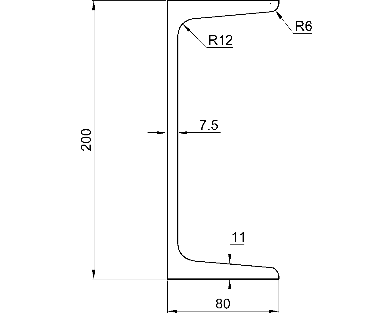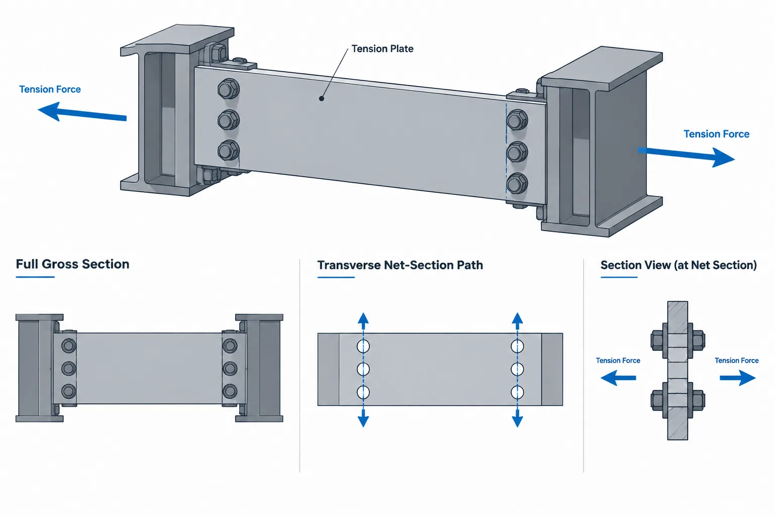
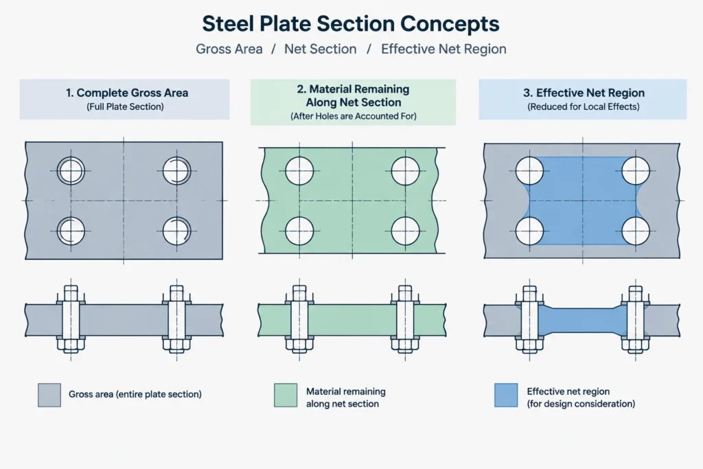
A steel tension member may have several relevant cross-sectional areas even though its shape designation identifies only one physical section. Gross area describes the complete cross section. Net area accounts for material removed by holes or other interruptions. Effective net area further accounts for the way force enters the connected parts of the section.
These distinctions matter when checking plates, angles, channels, tees, W-shapes, HSS, and built-up members. They also affect how connection geometry should be represented in CAD. A model can show the correct outside profile and still provide the wrong basis for a tension calculation if holes, connected elements, or possible failure paths are misunderstood.
Three area concepts with different purposes
| Area term | Typical notation | What it represents | Primary detailing question |
|---|---|---|---|
| Gross area | Ag | The full cross-sectional area before deductions for connection holes | What is the complete member section at the location being checked? |
| Net area | An | The remaining area along a selected section after applicable deductions | Which holes or interruptions cross the possible failure path? |
| Effective net area | Ae | Net area adjusted for nonuniform force transfer, commonly called shear lag | Are all parts of the cross section connected effectively? |
The three values are not interchangeable. Gross area is associated with behavior of the complete section, while net and effective net areas are used where a reduced section or incomplete connection changes how tension is carried. The governing design standard determines the applicable limit states, equations, and factors.
Gross area starts with the complete section
For a rolled shape, gross area is normally obtained from verified shape data rather than reconstructed from rounded nominal dimensions. A CAD outline calculated from simplified flange, web, or corner geometry may not reproduce the published area because rolled fillets, wall conventions, and database precision affect the result.
For a plate, gross area is based on its full width and thickness at the section under consideration. For a built-up tension member, the relevant gross area may include multiple components, but only if those components participate as part of the member being evaluated.
Bolt holes do not reduce gross area. They become relevant when evaluating a net section. This distinction is useful on drawings because a part can have one gross area while having several possible net areas at different connection rows.
Net area follows a possible section through the holes
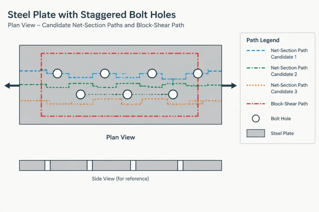
Net area is not simply the gross area minus every hole in the connection. It is evaluated along a potential failure path through a particular cross section. For a straight transverse row, that path may pass through multiple holes at the same member station. For staggered holes, alternative paths may cross different combinations of holes and diagonal segments.
The governing path is the one that produces the relevant lowest net area after applying the required calculation rules. A visually short path is not automatically the critical one. The drafter or checker should identify all credible paths rather than inspecting only one bolt row.
Hole deductions are a calculation input
The width deducted in a net-section calculation is not always identical to the nominal bolt diameter or to a circle measured from a CAD file. Hole type, fabrication method, and the governing design provisions can affect the deduction used in calculations. Standard holes, oversized holes, and slots therefore should not be treated as equivalent.
This creates an important separation between three pieces of information:
- Bolt diameter identifies the fastener.
- Detailed hole geometry communicates what is to be fabricated.
- Design hole deduction is the value required for the applicable net-area check.
A detail should clearly identify the hole type and orientation. The calculation should independently confirm the deduction required by the selected standard rather than relying on the diameter of a CAD object.
Slots require directional thinking
A slot has both a width and a length, so its effect depends on how the candidate section crosses it. Slot orientation also communicates whether movement or erection adjustment is intended. A calculation sketch should show the slot direction, the force direction, and the assumed failure line. Reducing a slot to a generic round-hole symbol can conceal information needed for both design and fabrication.
Effective net area accounts for shear lag
Even after hole deductions are established, the entire net section may not reach the same tensile stress at the same location. If force enters through only part of the section, stress must spread into outstanding elements over a finite connection length. This nonuniform transfer is commonly described as shear lag.
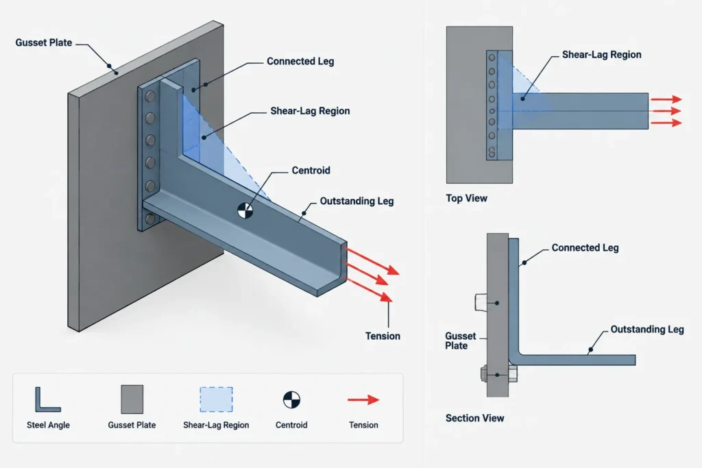
Effective net area is commonly expressed as net area modified by a shear-lag factor. The factor and its permitted calculation depend on member geometry, connection arrangement, and the governing design provisions. It should not be selected solely from the appearance of the detail.
Connection length can matter because a longer transfer region generally gives force more distance to spread through the cross section. Eccentricity between the connected plane and the member centroid may also influence the prescribed treatment. However, these observations are not substitutes for applying the correct standard provisions.
How member shape changes the force-transfer question
Plates
A plate connected across its width may have comparatively direct force transfer, but the actual bolt or weld arrangement still controls. Narrow connection zones, interrupted welds, edge distances, slots, and staggered holes can change the relevant section. Do not assume that a plate automatically has an effective net area equal to its net area.
Single angles
A single angle is often connected through one leg while the other leg remains outstanding. The connection plane is offset from the section centroid, and the outstanding leg does not receive force as directly as the connected leg. This makes the distinction between net area and effective net area especially important.
CAD placement should preserve which leg is connected. Mirroring an angle without updating the connection can change the physical arrangement even if the piece still looks plausible in an isolated view.
Channels and structural tees
A channel may be connected through its web, through its flanges, or with connection material engaging multiple elements. A tee may be connected through the stem or flange. Each arrangement transfers force into the section differently. The shape designation alone does not establish the effective connection geometry.
W-shapes
A W-shape connected only through its web does not receive force in the same manner as a detail that directly engages both flanges. End plates, splice plates, gussets, and weld layouts can produce different force-transfer conditions. Calculations and drawings should identify which elements are connected rather than referring generally to a connected W-shape.
HSS members
HSS tension connections can involve end plates, cap plates, slotted gussets, through plates, or welds around only part of the perimeter. The closed section may appear uniform away from the connection, but force entry near the end can be highly dependent on the detail. Wall faces, corner regions, slots, weld terminations, and connection length all require coordinated treatment.
Net-section rupture is not block shear
A net-section path generally crosses the member approximately transverse to the tensile force. Block shear involves a group of connected material bounded by combined tension and shear paths. Both checks may involve bolt holes, but they represent different potential failure mechanisms and should be sketched separately.
Likewise, checking effective net area does not replace checks for gross-section behavior, connection bearing, bolt behavior, weld strength, local effects, or the connected gusset and supporting member. The connection must be reviewed as a complete load path.
A practical CAD and calculation workflow
- Confirm the member identity. Verify the plate size or shape designation, orientation, material specification, and source of section data.
- Mark the force direction. A net-section sketch without a clear tension direction is easy to misread.
- Identify connected elements. Note whether force enters through a plate width, angle leg, web, flange, HSS face, or combination of elements.
- Verify every hole. Check diameter designation, hole type, slot direction, quantity, and center coordinates against the detail.
- Sketch candidate paths. Include straight and staggered paths where applicable. Keep net-section paths separate from block-shear paths.
- Determine net area using the governing rules. Do not use the visible CAD opening as an automatic design deduction.
- Evaluate shear lag. Confirm the applicable effective-area provisions using the actual connection length and geometry.
- Coordinate revisions. If bolt rows, end distances, member sizes, or connected elements change, repeat the area and load-path checks.
Common mistakes to avoid
- Using published gross area as though it already accounts for connection holes.
- Subtracting all holes in a connection rather than those crossing a candidate section.
- Using bolt diameter as the hole deduction without checking the applicable rules.
- Ignoring staggered failure paths.
- Assuming effective net area always equals net area.
- Applying a shear-lag factor from a superficially similar connection with different connected elements.
- Mirroring an angle, channel, tee, or HSS detail without rechecking orientation and force transfer.
- Treating net-section rupture and block shear as the same calculation.
What the drawing should communicate
A useful connection drawing does not need to show the area calculation, but it must provide enough reliable geometry for the calculation to be reconstructed. That includes the member orientation, plate limits, hole types, slot directions, bolt layout, connected elements, weld extents, and controlling datums.
The central question is not merely how much steel remains. It is how much steel remains along the critical path and how effectively the connection delivers force to that material. Keeping gross area, net area, and effective net area separate makes both structural checks and detailing reviews more dependable.