Fillet welds are common in structural steel connections because they can join plates and shapes without extensive edge preparation. Their geometry can still be misunderstood, especially when a drawing identifies a weld size but the CAD section appears to show a different dimension.
The key distinction is that fillet weld size usually refers to a leg dimension, not the visible weld face or the throat. Designers, detailers, fabricators, and inspectors need to interpret these terms consistently. The required weld must also satisfy the governing design documents, welding requirements, and approved connection details; a generic CAD triangle is not a substitute for engineering information.
The basic parts of a fillet weld
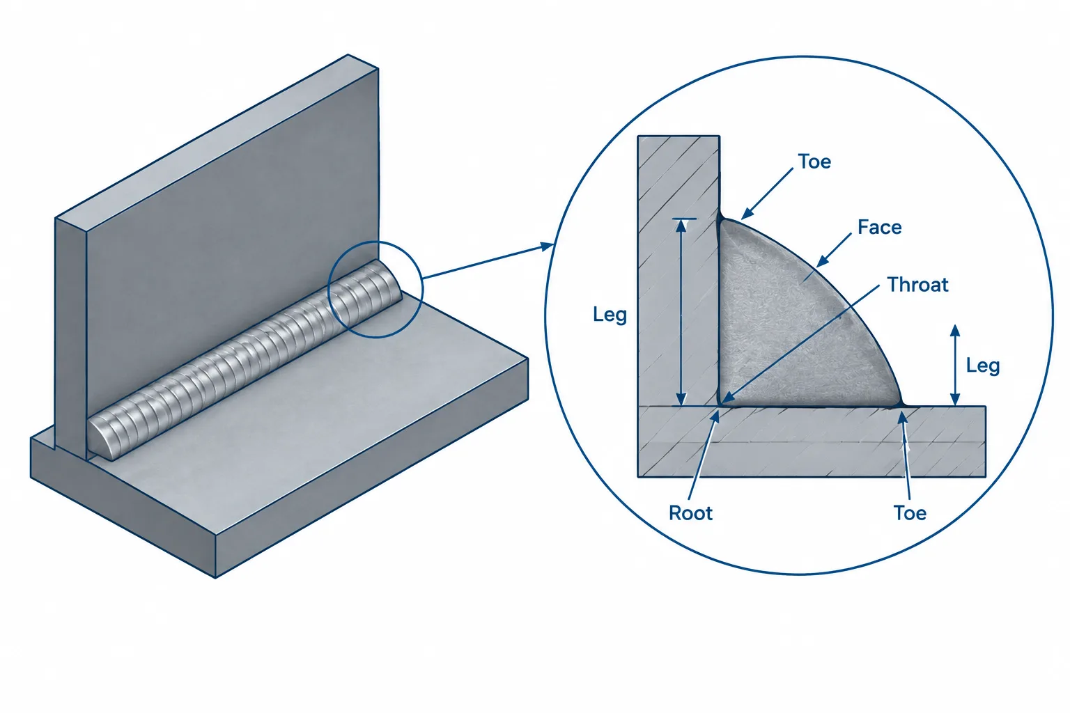
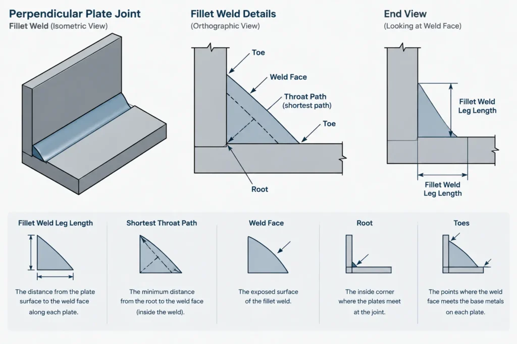
A fillet weld is placed at the intersection of two surfaces, commonly where one plate meets another plate or a steel-shape surface. In an idealized cross-section, its principal geometric features are:
- Root: The point or region where the joined surfaces intersect beneath the weld.
- Toes: The boundaries where the weld face meets the base metal.
- Face: The exposed surface extending between the toes.
- Legs: Distances measured from the root to the toes along the surfaces of the connected parts.
- Throat: A distance measured from the root toward the weld face, rather than along either connected surface.
These terms describe different measurements. Measuring diagonally across a drawn weld face and calling that result the weld size is generally incorrect. Likewise, the throat should not be assumed to equal a leg dimension.
What fillet weld size means
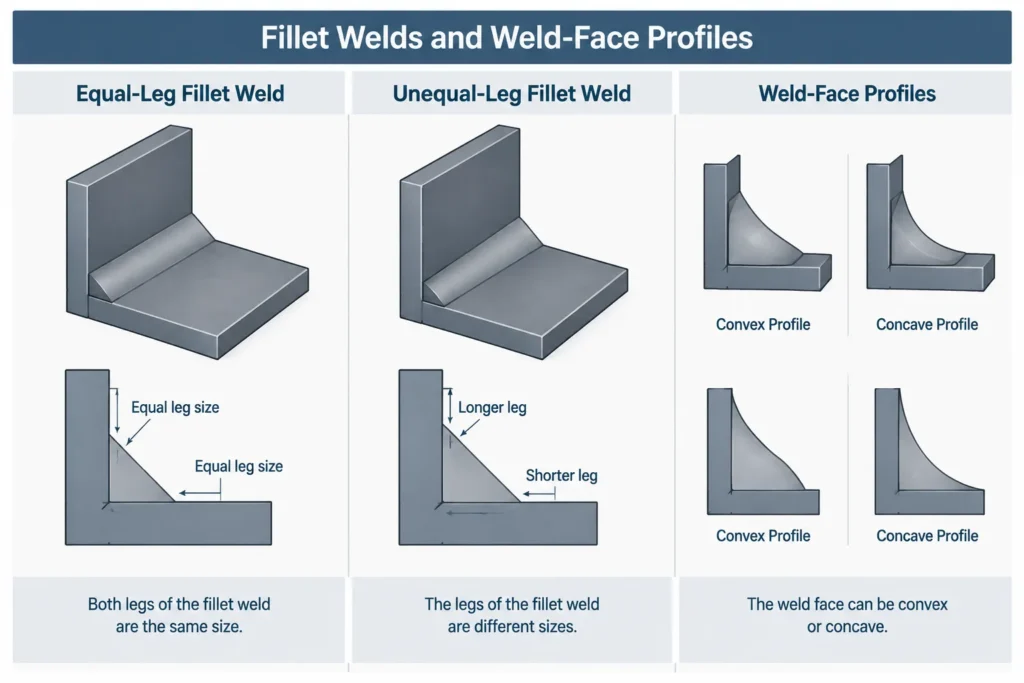
For a conventional equal-leg fillet weld, the specified size corresponds to the leg length represented by the weld symbol and connection requirements. Both legs are intended to have the same nominal size unless an unequal-leg weld is specifically identified.
The leg is measured along the surface of the base metal from the weld root to the weld toe. This matters when checking a drawing because the leg follows each joined surface; it is not the shortest line through the weld and not the curved length of the face.
A drafting symbol communicates the specified weld requirement. It does not necessarily reproduce the exact deposited profile at drawing scale. Shop drawings should therefore rely on clear weld symbols and notes rather than expecting a scaled triangular graphic to define fabrication.
Leg length versus throat
The throat represents the load-transfer dimension through the fillet weld cross-section. For an idealized equal-leg weld joining perpendicular surfaces, the theoretical throat is the shortest distance from the root to the idealized weld face. Because this line runs diagonally through the section, it is shorter than either leg.
Design calculations may refer to a theoretical, effective, or actual throat depending on the governing provisions and the weld configuration. These terms should not be treated as interchangeable:
- Theoretical throat comes from the idealized geometry of the weld cross-section.
- Actual throat describes the throat present in the deposited weld profile.
- Effective throat is the throat recognized for design under the applicable requirements.
A detailer should not derive an effective throat merely by scaling a drawing. The required fillet weld size and any special effective-throat requirement should come from the connection design and governing project criteria.
Equal-leg and unequal-leg fillet welds
Many simplified details depict an equal-leg triangular fillet. That representation is appropriate only when the intended weld has equal legs. Some joints require an unequal-leg fillet because of connection geometry, access, part thickness, load direction, or an engineered detail.
An unequal-leg weld has different dimensions along the two joined surfaces. Its orientation is therefore important: listing two dimensions without showing which applies to which surface can create ambiguity. A section, enlarged detail, or explicit notation may be needed to communicate the intended arrangement.
Do not assume that rotating a generic weld triangle is enough. The drawing should establish the connected parts, arrow side or other side, weld extent, and the orientation of any unequal legs.
Weld face profile does not automatically change the specified size
A deposited fillet weld may have a flat, convex, or concave face. The specified leg size remains a separate concept from the visible contour.
- A convex face projects outward beyond the idealized straight face.
- A concave face curves inward between the toes.
- A nominally flat face approximates the straight line used in the idealized geometric model.
Extra reinforcement on a convex face should not automatically be counted as additional effective throat. Conversely, a strongly concave profile can affect the available throat even when the toe-to-root legs appear adequate. Acceptance depends on the applicable welding criteria and inspection method, not on the appearance of a CAD triangle alone.
Common fillet-weld detailing mistakes
| Detailing issue | Why it causes problems | Better practice |
|---|---|---|
| Dimensioning the visible weld face as the weld size | The face is not the standard leg measurement. | Identify the weld through the appropriate weld symbol and required size. |
| Using a scaled triangle without a weld callout | Plot scale and schematic graphics do not provide reliable fabrication requirements. | Treat graphics as explanatory and symbols as the primary instruction. |
| Showing equal legs where unequal legs are intended | The fabricator may not know which dimension belongs on each surface. | Add an oriented section or explicit unequal-leg notation. |
| Calling out a weld where the electrode cannot reach | The weld may be difficult or impossible to deposit and inspect. | Check access, sequence, member geometry, and nearby obstructions. |
| Allowing the weld graphic to overlap a rolled fillet | The idealized root may not exist at the drawn sharp corner. | Coordinate with the actual shape profile, including rolled radii and k-region geometry. |
| Leaving weld length or limits unclear | The shop cannot determine whether the weld is continuous, intermittent, or locally terminated. | Define extent using the project’s accepted symbol and detailing conventions. |
Rolled-shape geometry can affect weld placement
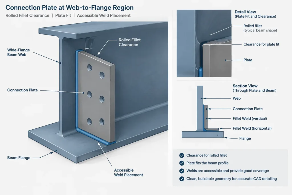
A plate welded to a W-shape, channel, angle, tee, or HSS does not always meet a perfectly sharp and unobstructed corner. Rolled sections contain fillets, radii, and transitions that can interfere with both the connected plate and the weld.
For example, a plate approaching the web-to-flange region of a rolled I-shaped member may need clearance from the rolled fillet. Moving the plate, clipping a corner, or changing the weld arrangement can alter the intended load path and must be coordinated with the connection design. The detail should not simply force a sharp-corner CAD plate into curved steel geometry.
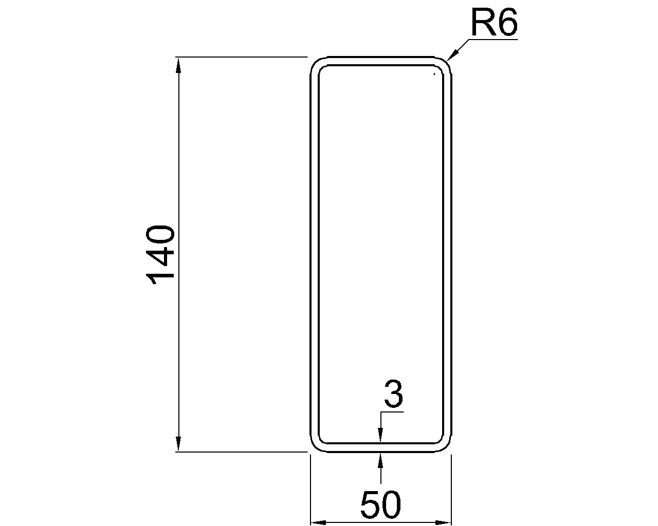
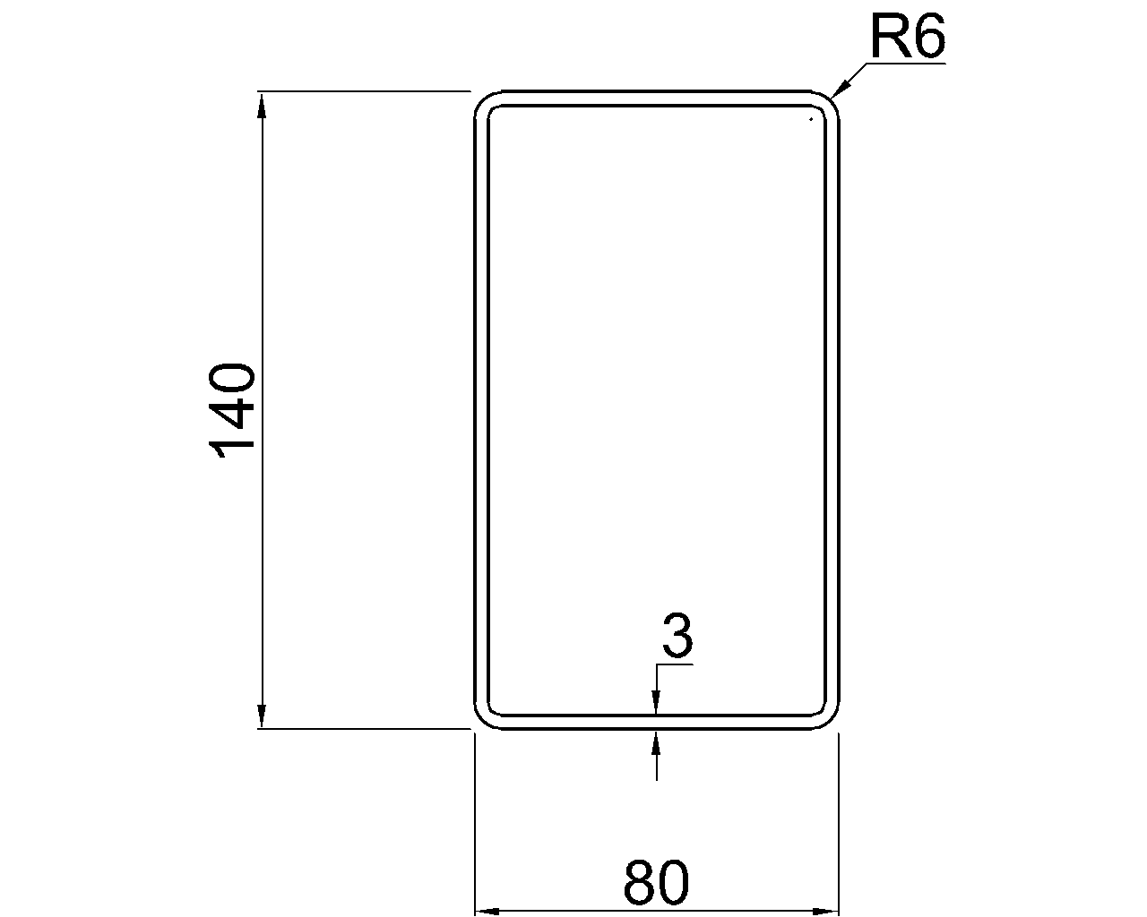
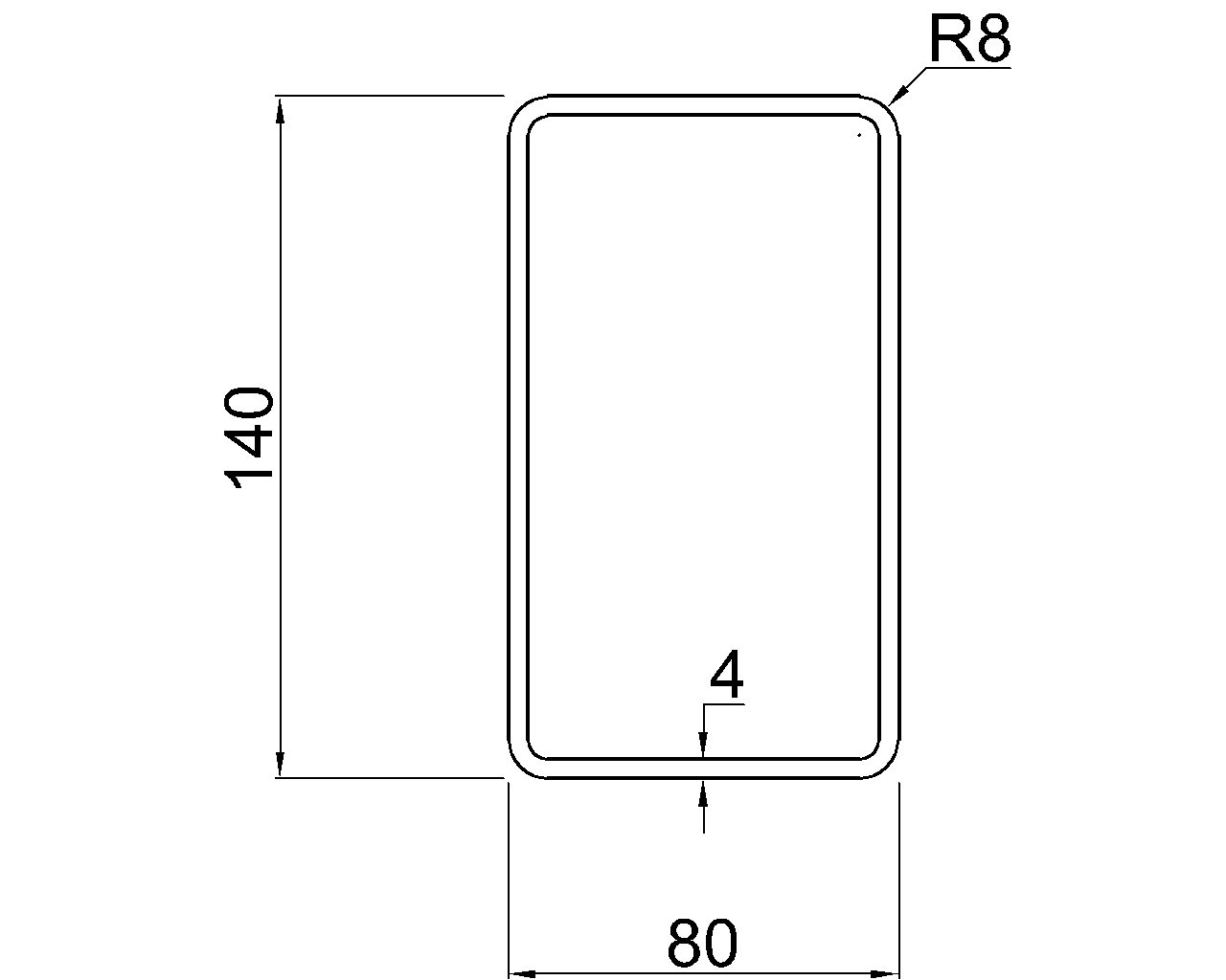
HSS connections introduce different concerns. Rounded outside corners can change where a plate bears and where a fillet weld can be deposited. The actual product geometry, weld seam location when relevant, and access around the tube should be considered rather than relying only on nominal rectangular outlines.
Representing fillet welds in CAD details
A good CAD workflow separates the instruction from the illustration. The weld symbol, reference line, arrow, size, length, and supplementary information communicate the requirement. A sectional weld bead can help readers understand the joint, but it should remain secondary.
Recommended drafting workflow
- Model or draw the actual connected steel surfaces before placing the weld.
- Check for rolled fillets, corner radii, plate edges, bolt heads, and other access restrictions.
- Confirm which side of the joint the arrow identifies.
- Use the project’s established weld-symbol convention consistently.
- Show weld length, limits, returns, and intermittent spacing only when required by the design documents.
- Use an enlarged section when unequal legs, skewed surfaces, or unusual joint geometry cannot be understood in the primary view.
- Avoid measuring the displayed weld bead to recover design information.
Reusable CAD weld blocks should be treated as editable graphic tools, not approved connection details. Before reuse, verify the arrow direction, symbol side, units, scale behavior, text style, layer, and all weld-specific data.
Weld size is only one part of the connection
A fillet weld callout does not by itself establish that a connection is adequate or constructible. The connection also depends on weld length and placement, connected material geometry, load path, base-metal behavior, fit-up, access, welding process, fabrication sequence, and applicable quality requirements.
When reviewing a detail, ask three separate questions: What weld is required? Where does it begin and end? Can it be made and inspected in the shown geometry? Keeping these questions separate helps prevent a visually complete drawing from concealing missing technical information.
Practical review checklist
- Is the fillet weld size identified as a leg dimension rather than a face measurement?
- Are equal or unequal legs communicated correctly?
- Is the arrow-side and other-side intent unambiguous?
- Are weld length and termination limits clear where needed?
- Does the connection account for rolled fillets, radii, and HSS corners?
- Is there sufficient access for deposition and inspection?
- Does the CAD graphic agree with the written weld information?
- Have project-specific design and welding requirements been verified?
Clear fillet-weld detailing begins with correct terminology. Leg length defines the conventional weld size, the throat describes a different path through the weld, and the visible face is not a substitute for either. When drawings distinguish these concepts and account for real steel geometry, they become easier to fabricate, review, and coordinate.