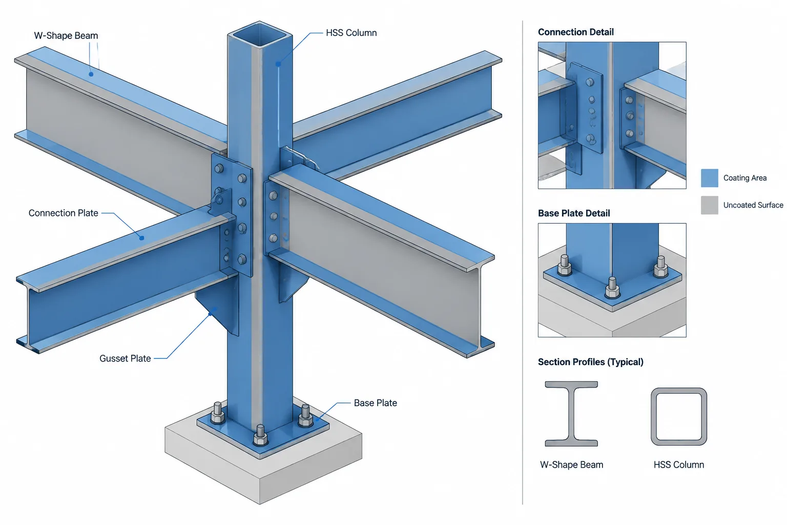
Structural steel surface area estimation is different from calculating steel weight. Weight is based on cross-sectional area, density, and length, while coating area depends on which faces are exposed and how the member is fabricated. A beam with end plates, stiffeners, copes, and connection material may have nearly the same weight as its preliminary model but a noticeably different paintable surface.
For practical takeoffs, the central idea is simple: multiply the exposed perimeter of a constant cross section by its length, then account for ends, cuts, plates, attachments, contact faces, and excluded surfaces. The difficulty lies in defining the correct perimeter and deciding what the coating scope actually includes.
The basic perimeter-times-length method
For a straight member with a constant cross section, its longitudinal surface area can be expressed as:
Along = Pexposed × L
In this expression, Pexposed is the perimeter of the cross section that will receive the coating, and L is the coated member length. The result covers surfaces running along the member. It does not automatically include end faces, copes, holes, end plates, stiffeners, or other fabrication features.
Unit consistency is essential. Perimeter and length must use compatible units, and the resulting square units must be converted to the units used by the estimator, coating supplier, or project documentation.
What counts as an exposed perimeter?
The exposed perimeter is not always the same as the complete geometric perimeter. It is the sum of the cross-section boundaries that are accessible and included in the coating scope.
W-shapes, channels, angles, and tees
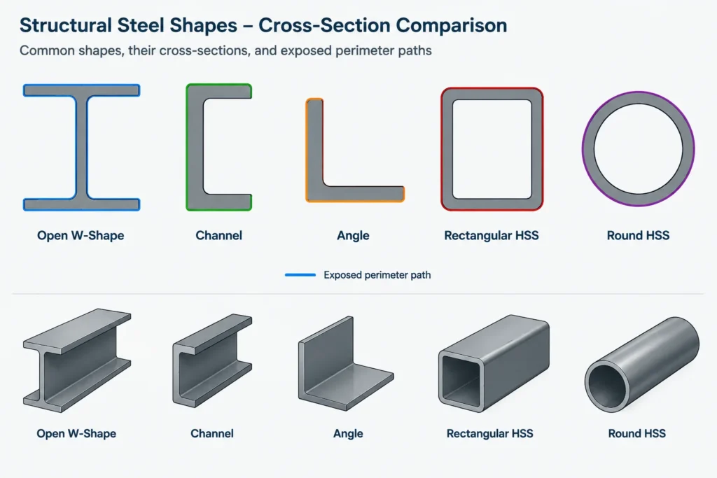
For open rolled shapes, the perimeter generally follows the accessible faces around the flanges, web, legs, or stem. A simple sharp-corner CAD outline may not reproduce rolled fillets, flange slopes, toe radii, or other manufacturing geometry exactly. That difference may be unimportant for a preliminary estimate but should not be mistaken for a verified production quantity.
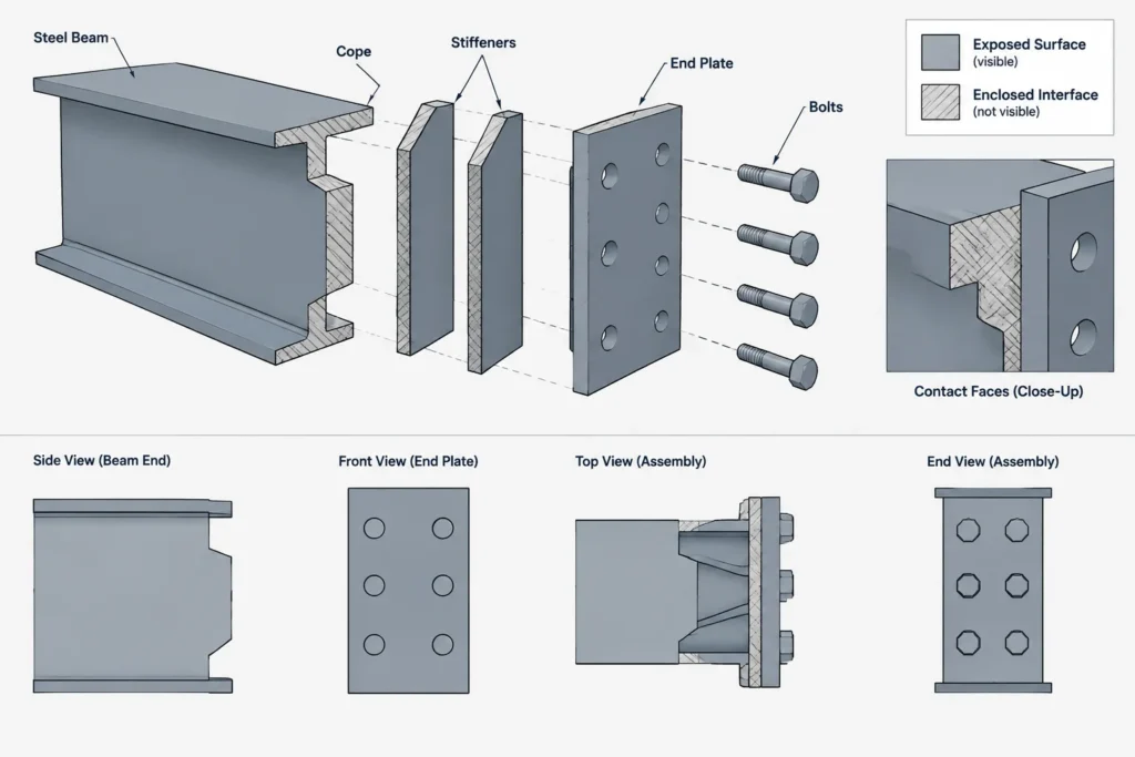
Contact areas also require attention. Examples include back-to-back angles, paired channels, bearing surfaces, and plates fitted directly against a flange or web. A surface hidden after assembly may still need shop preparation or coating before assembly, or it may be excluded entirely. The project coating requirements must resolve that question.
Round, square, and rectangular HSS
For HSS, the exterior perimeter is commonly used when only the outside surface is coated. The interior should not be added automatically. Whether an HSS interior is accessible, sealed, vented, galvanized, internally coated, or left untreated depends on the member configuration and project requirements.
For square and rectangular HSS, using only straight side dimensions ignores rounded corners. A verified published value or an accurate section profile is preferable when the required estimate must reflect the manufactured contour. For round HSS or pipe, the exterior circumference provides the longitudinal exterior perimeter.
Built-up members
A built-up member should be evaluated in its assembled condition. Adding the complete perimeter of every plate can double-count faying surfaces and other interfaces enclosed by welding or bolting. Instead, trace the external boundary of the completed cross section and separately identify any internal surfaces that remain open and are included in the coating scope.
Items that perimeter times length does not capture
The basic method handles prismatic longitudinal surfaces. Fabricated assemblies normally require adjustments.
| Item | Takeoff consideration |
|---|---|
| Member ends | Add exposed cut faces when they are included in the coating scope. |
| End plates and base plates | Include exposed broad faces and plate edges; avoid counting contact faces twice. |
| Stiffeners and connection plates | Add accessible faces and exposed edges, then deduct interfaces against the supporting member where appropriate. |
| Copes and notches | Remove deleted longitudinal material and add newly exposed cut surfaces when the required accuracy justifies it. |
| Bolt holes | Hole walls may be omitted in a preliminary estimate but should be handled consistently in a detailed method. |
| Welds | Weld profiles can change local surface area, although they are often treated according to an agreed estimating convention. |
| Open member interiors | Include only if the surfaces are accessible and explicitly part of the treatment scope. |
Small additions and deductions can offset one another, but that is not a reliable assumption for every assembly. A heavily plated connection, truss node, built-up column, or complex bracket can require a feature-based takeoff rather than a simple member allowance.
Net area versus gross estimating area
A useful workflow distinguishes between two levels of calculation:
- Gross estimating area: the basic member perimeter multiplied by length, usually with broad allowances for attachments.
- Net modeled area: the exposed faces of the fabricated assembly after cuts, holes, copes, plates, and contact interfaces are considered.
Gross area is useful during conceptual estimating because it is fast and repeatable. Net modeled area can support fabrication planning and detailed procurement, but only if the model represents the actual assembly and the exposed-face rules are correctly defined. More geometric detail does not automatically produce a more accurate coating quantity.
A practical CAD takeoff workflow
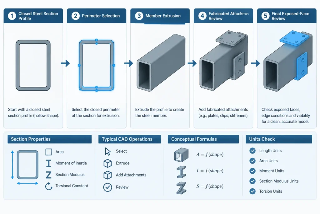
- Confirm the coating boundary. Identify which members, attachments, ends, interiors, and field-installed components are included.
- Classify the geometry. Separate constant-section members from plates, fittings, built-up members, and irregular assemblies.
- Verify member lengths. Decide whether each length is based on work points, cut length, overall assembly length, or another documented reference.
- Obtain the exposed perimeter. Use a verified shape reference or a controlled section profile. Do not assume that a visually similar CAD block has an accurate perimeter.
- Calculate longitudinal area. Apply the perimeter-times-length method to each constant-section member.
- Add fabricated components. Calculate plate faces, exposed edges, stiffeners, clips, and end components without double-counting interfaces.
- Review exclusions. Mark embedded steel, enclosed faying surfaces, inaccessible interiors, or areas assigned to a different treatment system.
- Apply the project estimating convention. Document how holes, welds, cut edges, and minor attachments are handled.
- Check units and totals. Keep the conversion method visible instead of relying on an unexplained software output.
Using CAD area and mass-property tools
A closed section profile can provide a perimeter, while a solid model can report surface areas for selected bodies or faces. These tools are useful, but their output must be interpreted. A solid may include end faces that a perimeter calculation omits, internal faces that will be sealed, or contact surfaces between components that should not be counted as externally exposed.
Confirm whether curved faces are represented as true curves or simplified segments. Also check for overlapping solids, duplicate plates, suppressed holes, and members extending beyond their final cuts. Surface-area commands calculate the geometry they receive, not the fabrication intent.
Common takeoff mistakes
- Using member weight as a direct substitute for coated surface area.
- Multiplying a bounding-box perimeter by length for an open steel shape.
- Counting both sides of a plate even when one side is fully enclosed against another component.
- Including HSS interior area without confirming access and coating scope.
- Ignoring end plates, stiffeners, clip angles, and other repeated attachments.
- Using centerline length where the required basis is actual cut length.
- Combining square inches, square feet, square millimeters, and square meters without a documented conversion.
- Treating a simplified CAD outline as an exact rolled-shape contour.
Document assumptions with the quantity
A coating-area total is most useful when another person can understand how it was produced. The takeoff record should identify the member list or model revision, length basis, section-profile source, included surfaces, excluded surfaces, treatment of holes and welds, and unit conversions.
The final quantity should also be kept separate from coating coverage or material-order calculations. Surface preparation, application method, required coating system, dry-film requirements, waste, overspray, and manufacturer guidance affect material consumption. Geometric area is an input to that process, not a complete paint order by itself.
For preliminary structural steel surface area estimation, exposed perimeter multiplied by member length is an efficient starting point. For fabricated assemblies, accuracy comes from combining that method with clear scope rules, disciplined CAD checks, and careful treatment of plates, ends, interfaces, and inaccessible surfaces.


