
Steel section tables commonly list two properties that look similar but describe different stages of flexural behavior: elastic section modulus, identified by S, and plastic section modulus, identified by Z. Both depend on cross-sectional geometry, and both are associated with bending about a specified axis. They are not interchangeable.
Understanding elastic versus plastic section modulus is useful when comparing W-shapes, channels, angles, structural tees, and other profiles. It also helps drafters and designers recognize why a member with more area is not automatically the most efficient option for a particular bending direction.
What Is Elastic Section Modulus?
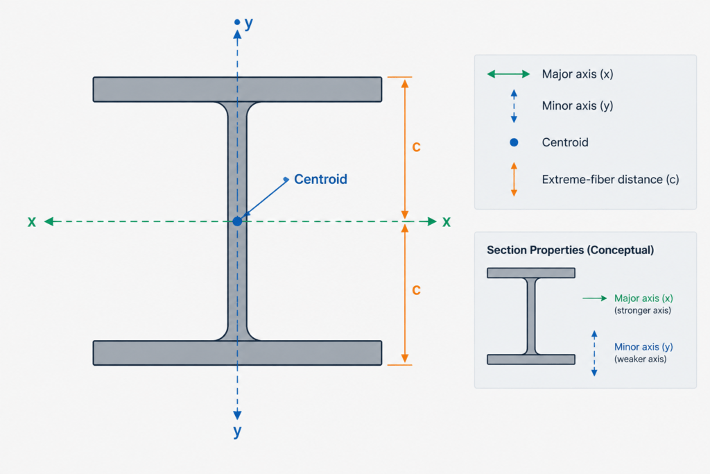
Elastic section modulus relates a section’s moment of inertia to the distance from its neutral axis to an extreme fiber. It is expressed geometrically as:
S = I / c
In this relationship, I is the second moment of area about the bending axis, and c is the perpendicular distance from that axis to the extreme fiber being evaluated. The result is a geometric property with units of length cubed.
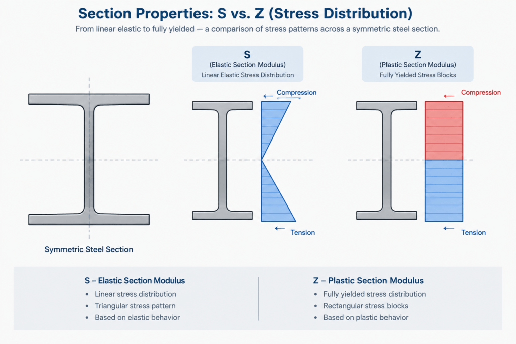
Elastic bending theory assumes that plane sections remain plane and that stress varies linearly through the depth of the section. Stress is zero at the elastic neutral axis and reaches its greatest magnitude at an extreme fiber. Within this idealized elastic range, bending stress may be related to moment by:
f = M / S
This expression is best understood as a relationship among moment, geometry, and extreme-fiber stress. It is not, by itself, a complete member-strength check.
Why the extreme-fiber distance matters
Two sections can have the same moment of inertia but different elastic section moduli if their extreme fibers are different distances from the neutral axis. A profile extending farther from the axis increases c, which affects the value of S. This is one reason section depth, flange placement, and asymmetry all matter when reading shape tables.
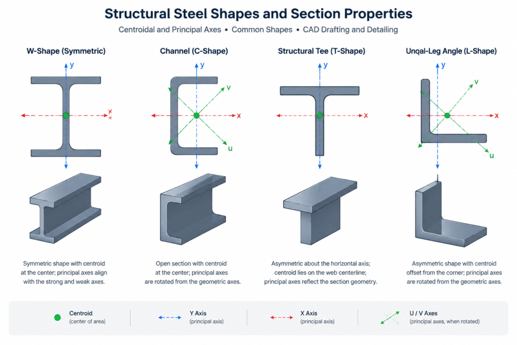
For a section symmetric about the relevant axis, the distances to the two extreme fibers are equal. For an unsymmetric section, the top and bottom distances may differ. In that case, separate elastic section moduli can apply to the opposite sides of the same axis.
What Is Plastic Section Modulus?
Plastic section modulus describes the distribution of cross-sectional area when the section is idealized as fully yielded in bending. Instead of using a linear stress pattern, the plastic model divides the section into compression and tension regions at the plastic neutral axis.
The plastic neutral axis is positioned so that the area in compression balances the area in tension for the usual idealized case of equal yield stress in both directions. Plastic section modulus is obtained by summing the first moments of these areas about that axis. Conceptually:
Z = sum of each area multiplied by the distance from its centroid to the plastic neutral axis
Like elastic section modulus, plastic section modulus has units of length cubed. Unlike S, it is not calculated simply by dividing moment of inertia by an extreme-fiber distance.
Elastic and plastic neutral axes are not always the same
For a doubly symmetric W-shape bending about a centroidal principal axis, the elastic and plastic neutral axes occupy the same centerline. That convenient result does not apply to every profile.
Channels, structural tees, unequal-leg angles, built-up members, and sections with holes or reinforcement may have different elastic and plastic neutral-axis locations. For these shapes, using the centroid as the plastic neutral axis without checking area balance can produce an incorrect result.
Key Differences Between S and Z
| Property | Elastic section modulus, S | Plastic section modulus, Z |
|---|---|---|
| Stress model | Linear elastic stress distribution | Idealized fully yielded stress distribution |
| Reference axis | Elastic neutral axis through the centroid | Plastic neutral axis based on area balance |
| Geometric basis | Moment of inertia divided by extreme-fiber distance | First moments of tension and compression areas |
| Common notation | Sx, Sy, or side-specific values | Zx and Zy |
| Typical use | Elastic stress calculations and section comparison | Plastic bending behavior and applicable strength calculations |
| Units | Length cubed | Length cubed |
For a typical solid steel section, Z is greater than S for the same bending axis. The difference represents the additional geometric contribution available as yielding spreads from the extreme fibers toward the neutral axis in the idealized bending model.
Major-Axis and Minor-Axis Values
Section modulus must always be read together with its axis designation. Shape tables often use x for the major principal axis and y for the minor principal axis, but users should confirm the axis diagram and conventions of the reference being used.
- Sx and Zx normally relate to bending about the x-axis.
- Sy and Zy normally relate to bending about the y-axis.
- The values describe bending about the named axis, not force acting along that axis.
- Rotating a shape in a CAD model does not change its geometric properties, but it can change which local axis corresponds to the project’s global direction.
A W-shape usually has substantially different behavior about its two principal axes because much of its flange area is positioned far from the major axis but relatively close to the minor axis. Channels and tees add another concern: their geometry may be symmetric about only one axis. Angles require particular care because their principal axes generally do not align with the leg directions.
What Is Shape Factor?
The ratio of plastic section modulus to elastic section modulus is commonly called the shape factor:
Shape factor = Z / S
This dimensionless ratio compares two idealized geometric bending measures for the same section and axis. A larger ratio indicates a greater difference between first yield at an extreme fiber and the fully plastic stress distribution, assuming the relevant idealizations can develop.
Shape factor should not be treated as a general efficiency score. It does not account for member length, lateral bracing, local slenderness, residual stress, connection behavior, holes, material selection, load combinations, or fabrication constraints. A section with a favorable shape factor may still be unsuitable for a given member or detail.
Why Z Does Not Automatically Equal Available Strength
Plastic section modulus is a cross-sectional property, not a promise that a real member can develop a fully plastic moment. Actual flexural behavior can be limited by conditions that are not represented in Z.
- Local buckling: Slender plate elements may buckle before the assumed stress distribution develops.
- Lateral-torsional buckling: An unbraced beam can move laterally and twist before reaching a cross-section-based limit.
- Unsupported length: Member behavior depends on restraint and bracing, not only section geometry.
- Openings and reductions: Copes, bolt holes, slots, notches, and other modifications can alter the effective section.
- Load introduction: Concentrated forces and connection geometry may create local limit states.
- Axis orientation: Biaxial bending or loading away from a principal axis requires more than a single tabulated modulus.
Design strength must therefore be determined using the applicable design standard, material data, member conditions, and project criteria. A table value should be treated as verified geometric input rather than a complete design result.
Practical Workflow for Reading a Shape Table
- Confirm the exact designation. Similar nominal-depth shapes may have very different flange and web proportions.
- Identify the bending axis. Check the section sketch instead of relying only on the column heading.
- Select the correct property. Use S for an elastic section-modulus calculation and Z only where a plastic property is appropriate.
- Check for asymmetry. Determine whether opposite extreme fibers require different elastic values.
- Verify units. Do not mix imperial and metric section properties or assume that a CAD file’s drawing units match the table.
- Review modifications. Confirm whether holes, cuts, reinforcement, or built-up components make the tabulated gross-section property inapplicable.
- Evaluate the whole member. Bracing, span, loading, connections, and stability remain separate considerations.
CAD and Detailing Implications
Section-property calculations depend on the actual profile, while many CAD blocks are simplified for drafting clarity. Fillets, corner radii, wall thickness, flange taper, or other profile details may be represented schematically. A block can therefore be useful for plans and details without being suitable as the source geometry for a property calculation.
When a custom section is created from CAD geometry, verify that the outline is closed, non-self-intersecting, and free of duplicate segments. Confirm whether voids are modeled as holes and whether the coordinate axes match the intended member axes. For HSS and other rounded profiles, replacing curved corners with sharp corners changes the area distribution and can affect calculated properties.
Keep the shape designation, orientation, material specification, and member mark as separate data fields where possible. This reduces the risk of assigning correct section properties to a member that has been rotated, renamed, or replaced during coordination.
A Useful Way to Remember the Difference
S describes the geometry used for a linear elastic extreme-fiber stress relationship. Z describes the geometry of an idealized fully yielded cross section. Both are axis-dependent, both require reliable source data, and neither substitutes for a complete structural check.
When comparing steel shapes, start by asking three questions: Which axis is bending? Is the calculation elastic or plastic? Does the real member have the stability and detailing needed for the assumed behavior? Those questions make the columns labeled S and Z far more useful than treating them as isolated table values.


