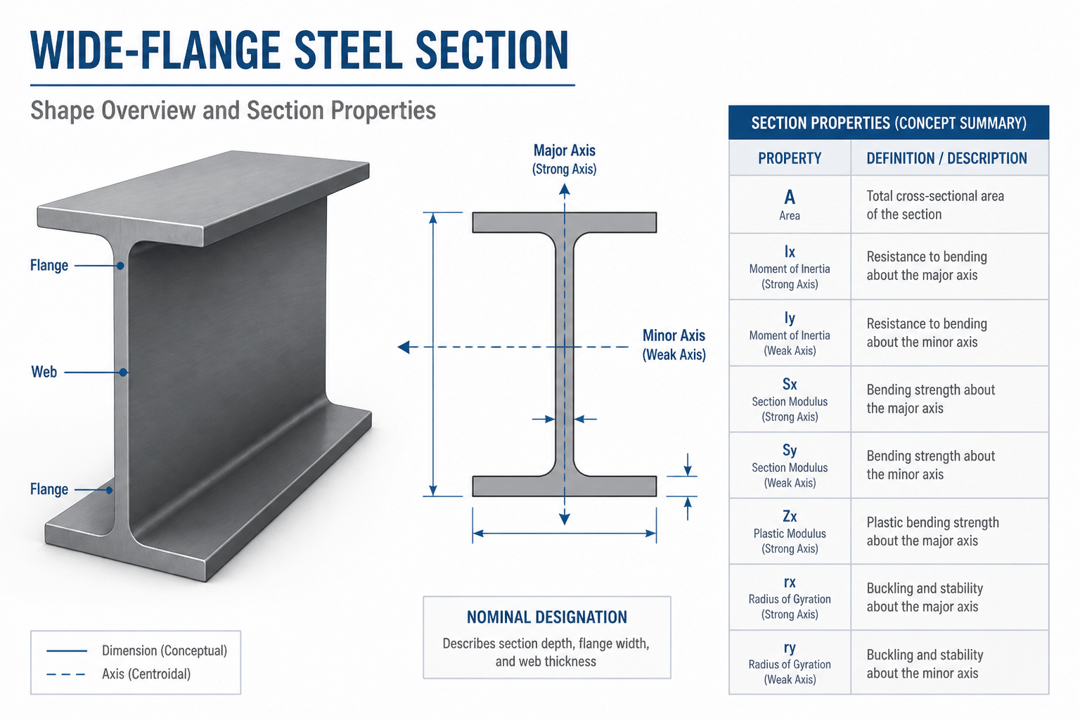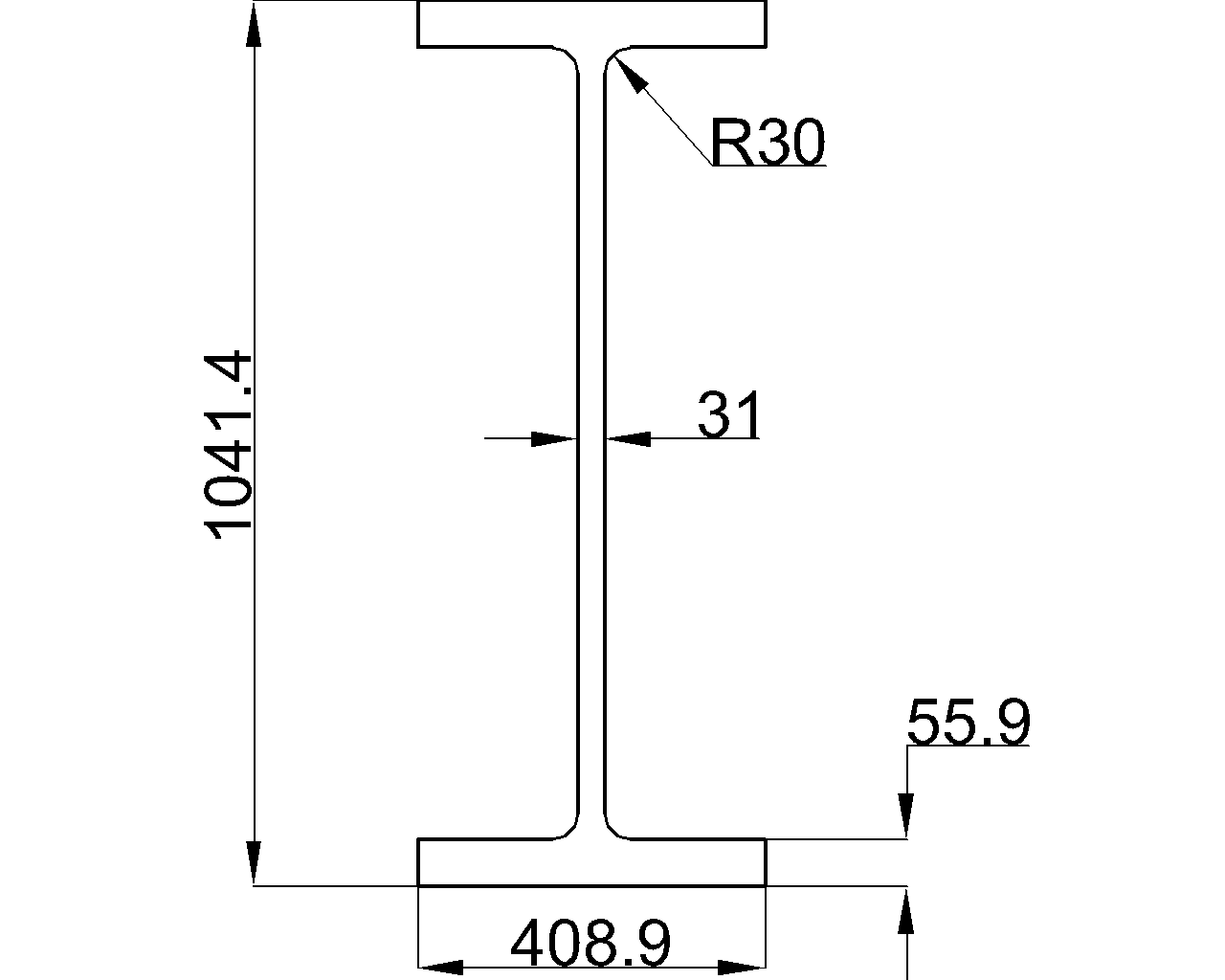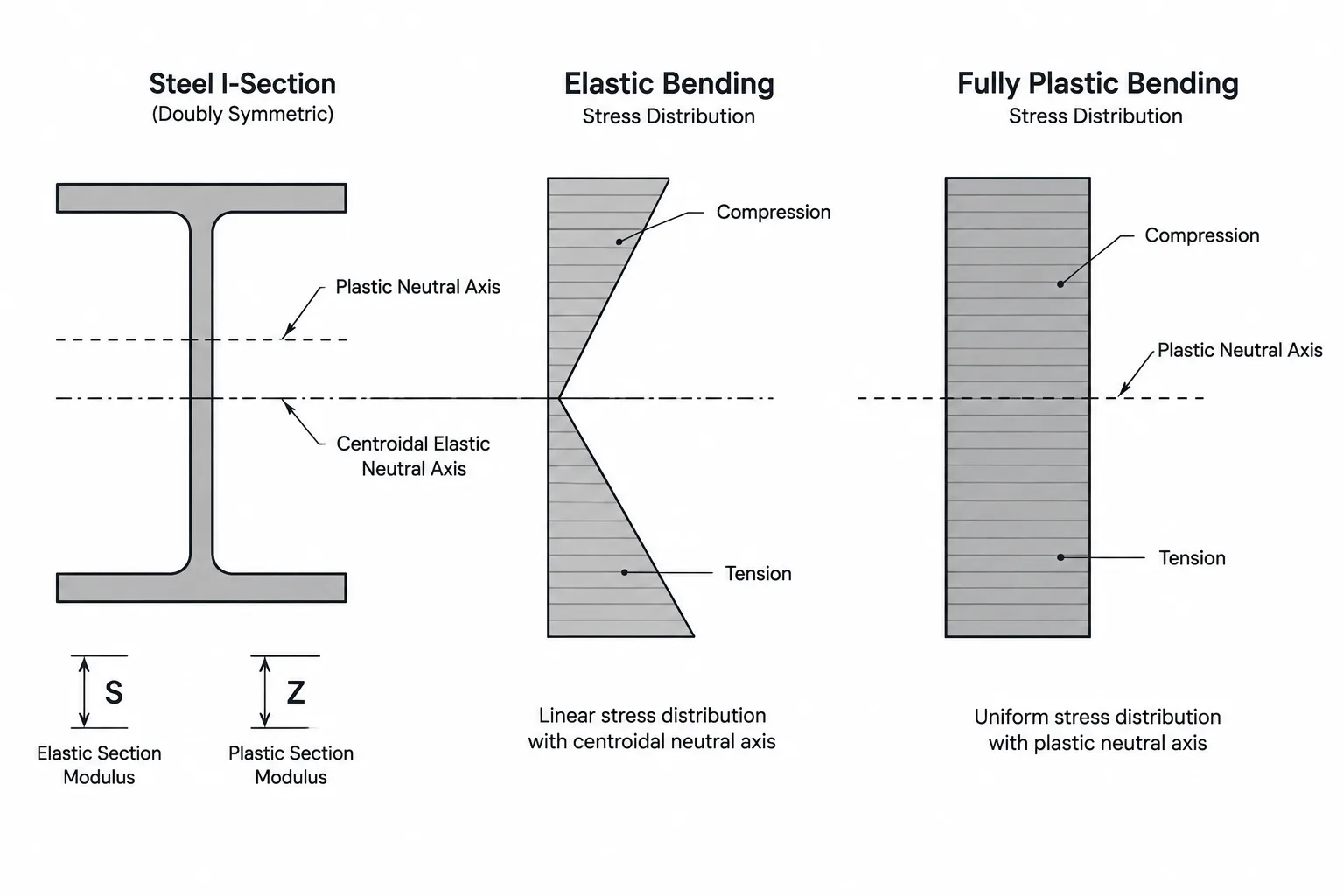
Structural steel shape tables commonly list both elastic section modulus and plastic section modulus. These properties are usually identified by S and Z, with axis subscripts such as Sx, Sy, Zx, and Zy. Although the values may appear side by side, they describe different stages of flexural behavior and should not be treated as interchangeable.
Elastic section modulus relates section geometry to bending stress while the cross section remains elastic. Plastic section modulus describes the geometry of a fully yielded stress distribution. Understanding that distinction is important when reading W-shape, channel, angle, tee, HSS, and built-up-member property tables.
What Elastic Section Modulus S Represents
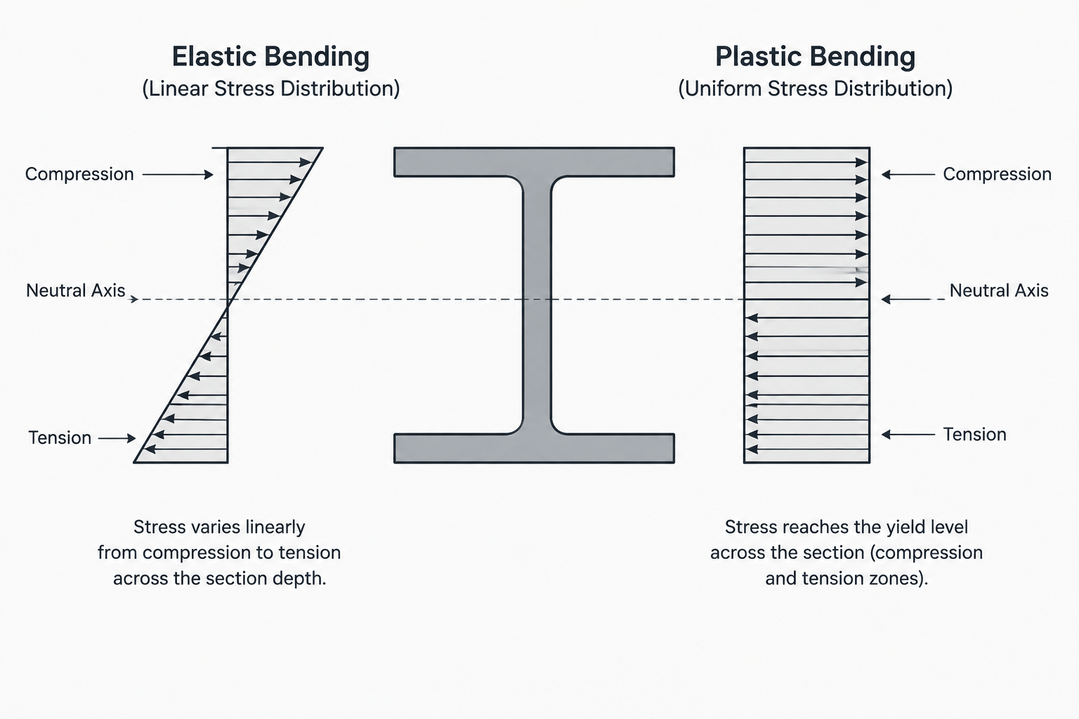
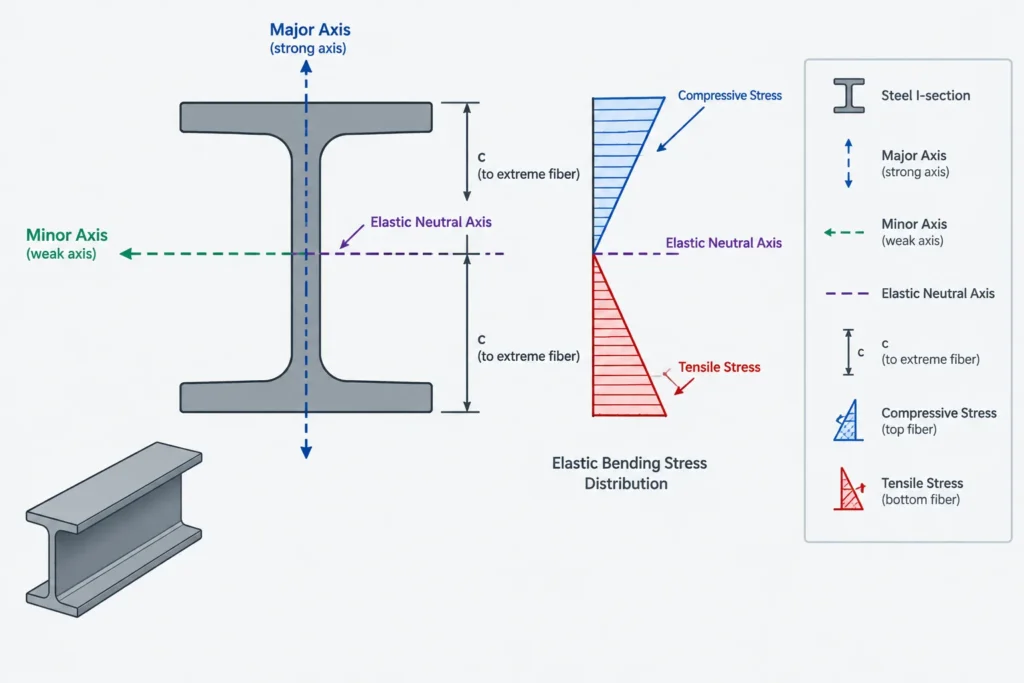
Under elastic bending, longitudinal stress varies linearly through the depth of the section. Stress is zero at the elastic neutral axis and increases toward the extreme fibers. The familiar elastic bending relationship uses the moment of inertia and the distance from the neutral axis:
S = I / c
Here, I is the area moment of inertia about the bending axis, and c is the perpendicular distance from that axis to the extreme fiber being checked. Section modulus packages those two geometric quantities into one value.
For a doubly symmetric W-shape bent about its major axis, the top and bottom extreme fibers are equally distant from the centroidal axis. A single listed value of Sx can therefore represent elastic bending in either direction. The same basic symmetry applies about the minor axis when the section is symmetric about that axis.
Unsymmetric sections require more attention. A channel, tee, single angle, or irregular built-up section may have different distances from its neutral axis to opposite extreme fibers. In that case, the elastic section modulus can differ by side:
- S for one extreme fiber is based on the distance to that fiber.
- S for the opposite extreme fiber is based on a different distance.
- The smaller value reaches a given elastic stress at a lower bending moment.
A table, calculation report, or software output should therefore be checked to determine which side or fiber each value represents.
What Plastic Section Modulus Z Represents
Plastic section modulus is associated with an idealized condition in which the entire cross section has reached yield in either compression or tension. Instead of a linear stress distribution, the idealized plastic distribution consists of compression over one part of the section and tension over the other.
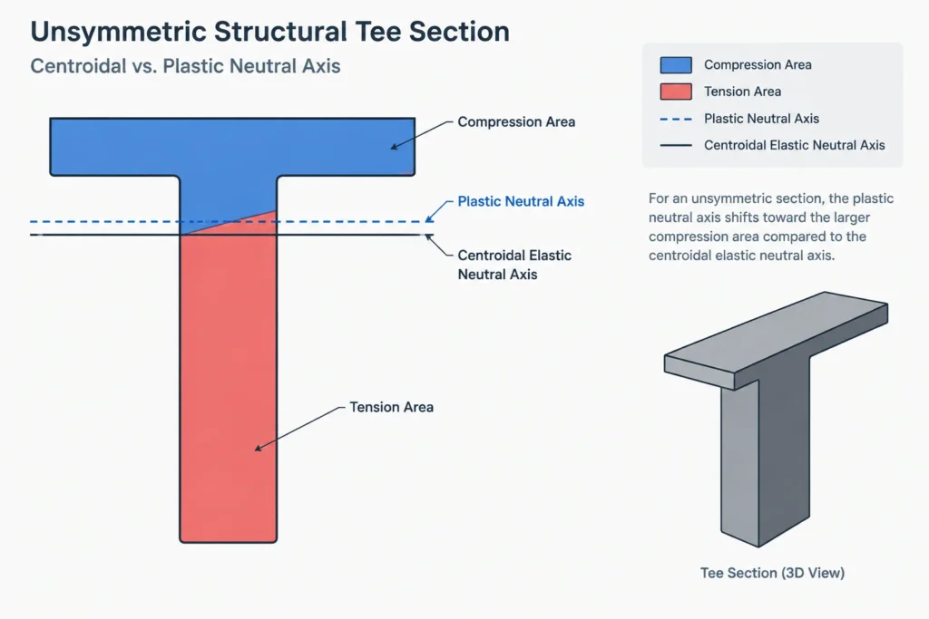
The dividing line is the plastic neutral axis. For a section made from one material with the same yield strength in tension and compression, this axis divides the cross-sectional area into equal areas. It does not necessarily pass through the centroid.
Plastic section modulus can be understood as the sum of the first moments of the compression and tension areas about the plastic neutral axis:
Z = Σ(A × distance to the plastic neutral axis)
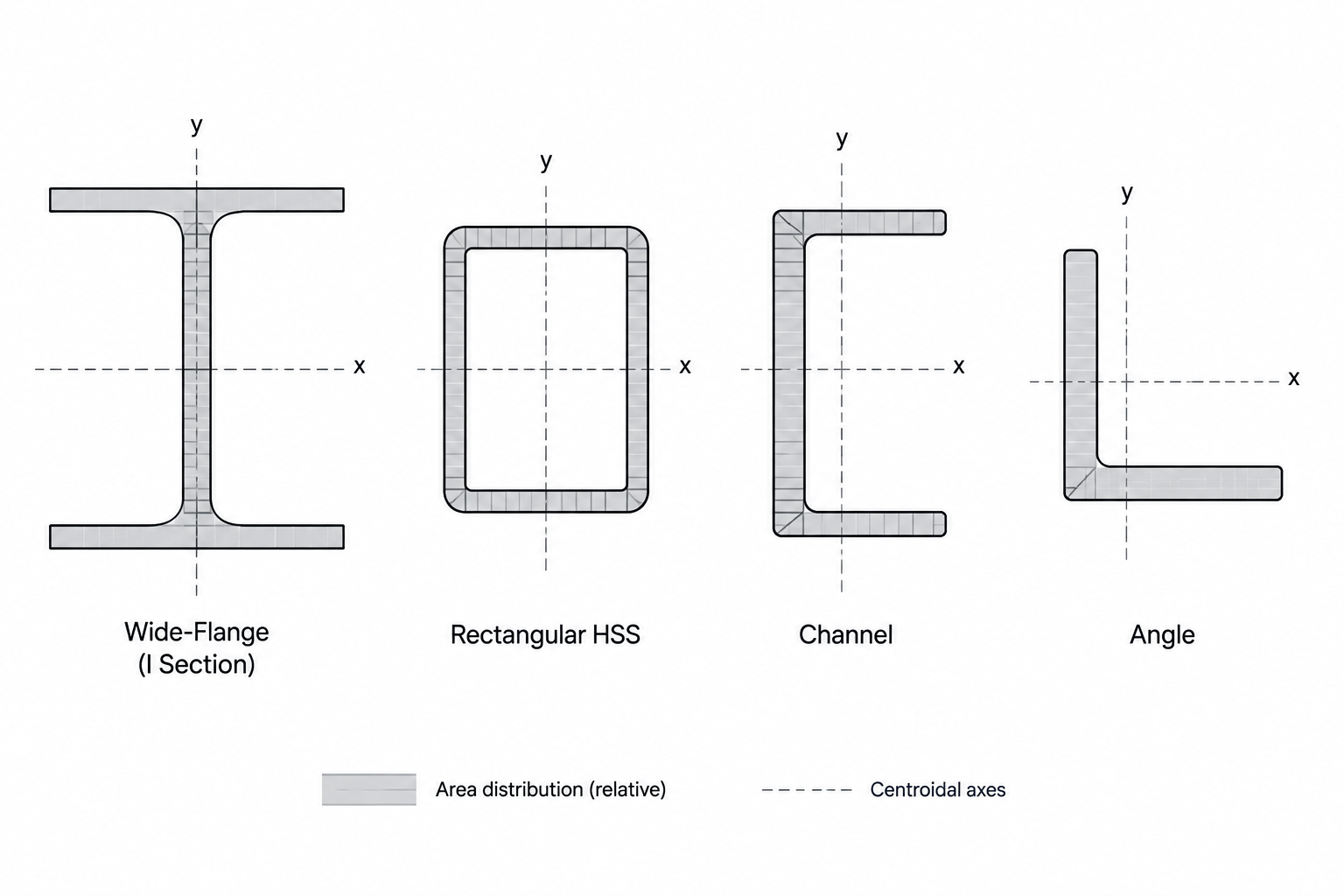
The expression is geometric. It adds the contribution of each area component using the distance from that component’s centroid to the plastic neutral axis. For a W-shape, those components may be organized as flange and web regions. For an HSS, the hollow interior and wall geometry must be represented correctly. For an angle or tee, locating the plastic neutral axis can be less intuitive because of the unsymmetric area distribution.
S and Z Compared
| Property | Elastic section modulus S | Plastic section modulus Z |
|---|---|---|
| Stress model | Linear elastic stress distribution | Idealized fully yielded stress distribution |
| Reference axis | Elastic neutral axis through the centroid | Plastic neutral axis dividing tension and compression areas |
| Geometric basis | Moment of inertia divided by extreme-fiber distance | Sum of area moments about the plastic neutral axis |
| Typical use | Elastic stress calculations and flexural reference | Plastic flexural strength calculations where permitted |
| Effect of asymmetry | May produce different values for opposite extreme fibers | Requires a separately located plastic neutral axis |
For ordinary compact shapes, Z about a given axis is generally larger than the corresponding elastic section modulus because yielding can spread beyond the first-yield condition. That comparison alone, however, does not establish an available member strength.
Shape Factor Z/S
The ratio of plastic section modulus to elastic section modulus is commonly called the shape factor:
Shape factor = Z / S
This dimensionless ratio compares the idealized fully plastic moment with the moment that first produces yield at the elastic extreme fiber, assuming the same yield stress is used for both comparisons.
Shape factor depends on how area is distributed about the bending axis. Material concentrated away from the neutral axis can influence S and Z differently from material near the axis. Consequently, a W-shape, rectangular HSS, channel, solid rectangle, and other profiles do not all have the same shape factor.
For an unsymmetric section, a simple Z/S statement can be ambiguous because S may differ on the two sides of the elastic neutral axis. The calculation or table should identify which elastic section modulus is being used in the comparison.
Why Z Does Not Automatically Equal Usable Flexural Strength
Plastic section modulus is a section property, not a complete design result. A member may be unable to develop a fully plastic stress distribution because another behavior controls. Relevant considerations can include:
- Local buckling of flange, web, or HSS wall elements
- Lateral-torsional buckling between brace points
- Overall member stability and unbraced length
- Material properties and the applicable resistance or safety format
- Holes, copes, notches, or section loss in critical regions
- Combined axial force, bending, shear, or torsion
- Connection geometry and the ability to transfer the required forces
- Applicable design-standard provisions and section classification
This is why multiplying Z by a material strength without checking the governing design method can produce an incomplete or unsafe conclusion. Published section properties provide geometry; the design procedure determines how that geometry may be used.
Reading Axis Subscripts Correctly
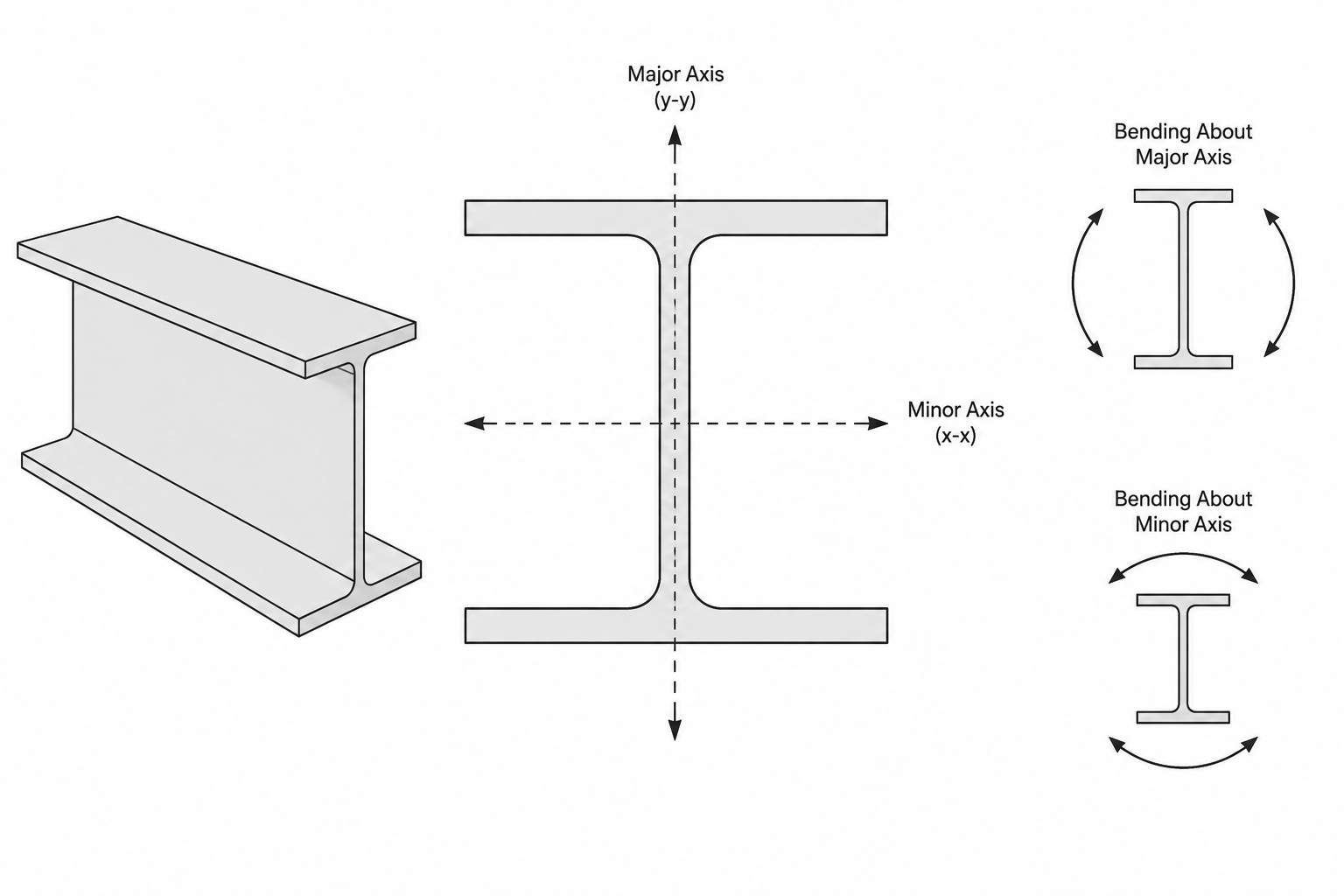
The subscript identifies the axis about which bending is being considered. For many North American shape tables, x denotes the major or strong axis and y denotes the minor or weak axis. That convention must still be verified when working with custom calculations, imported CAD geometry, analysis software, or international data sources.
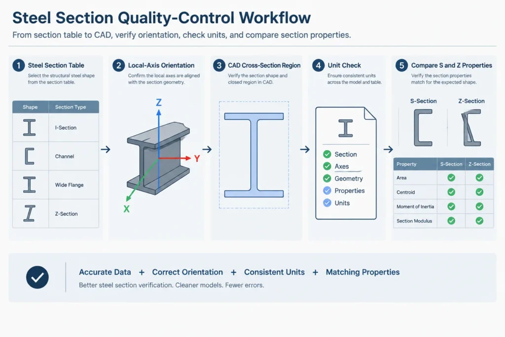
- Sx and Zx: properties for bending about the x-axis.
- Sy and Zy: properties for bending about the y-axis.
- Stop, Sbottom, or similar labels: side-specific elastic values for an unsymmetric section.
Section rotation in a CAD or analysis model does not change the physical properties of the shape, but it can change which global loading direction corresponds to the local x or y axis. A rotated channel or angle is a common source of axis confusion.
Practical Verification Workflow
When using S or Z from a steel shape database, calculation sheet, or CAD-derived profile, follow a consistent review process:
- Confirm the exact shape designation. Similar nominal depths do not guarantee identical properties.
- Check the bending axis. Match the listed local axis to the member orientation in the model and drawings.
- Identify symmetry. Determine whether opposite extreme fibers share one elastic section modulus or require separate values.
- Verify units. Section modulus uses units of length cubed. A unit mismatch can create a large calculation error.
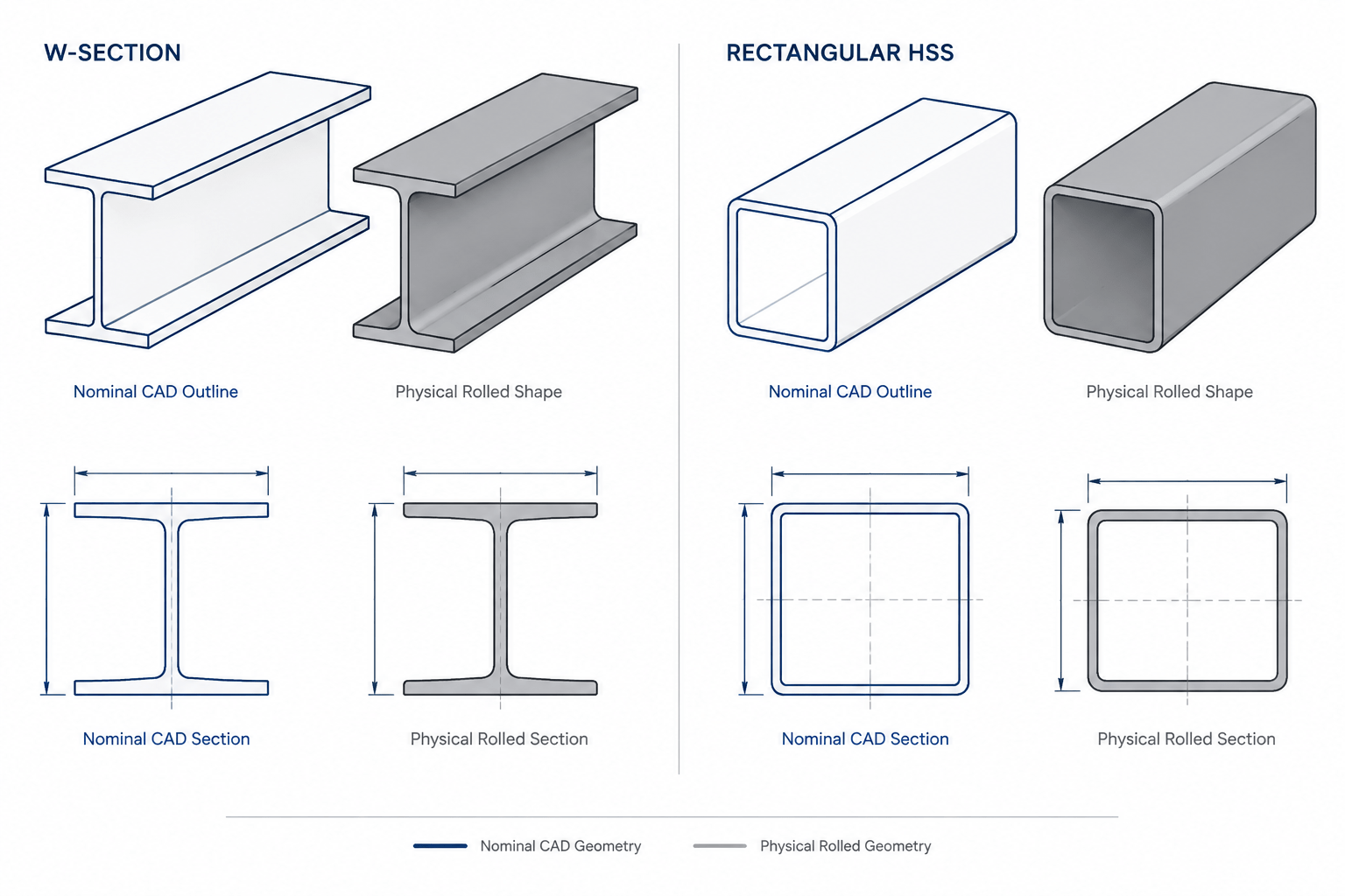
- Check the property source. Published values may use geometry conventions that differ from a simplified CAD outline.
- Do not infer capacity from geometry alone. Apply the appropriate design provisions and stability checks.
Why CAD-Calculated Values Can Differ
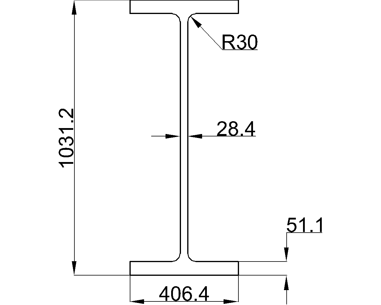
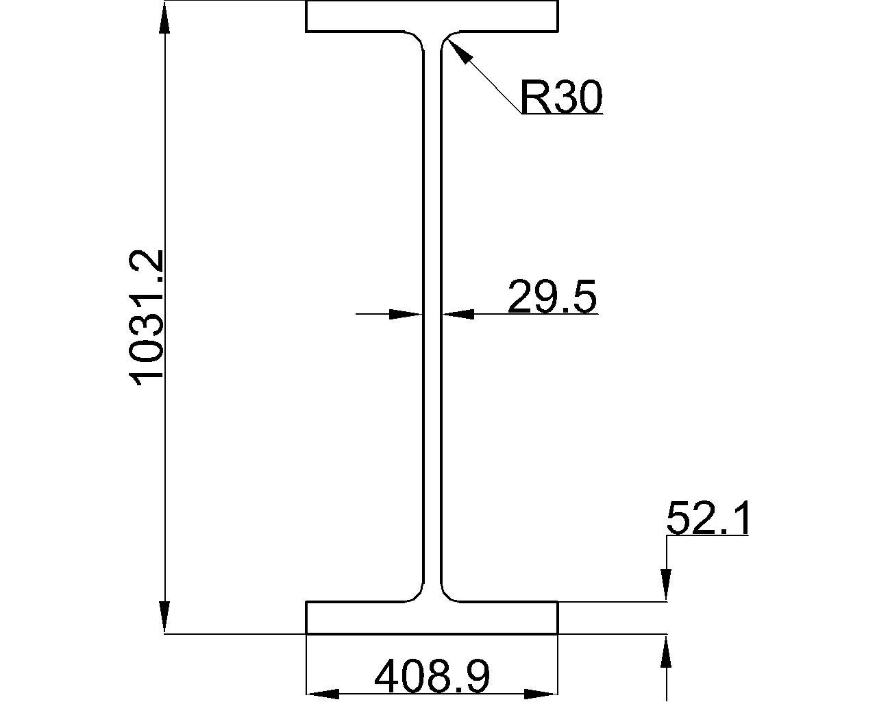
A closed CAD region can be used to calculate centroid, moment of inertia, and elastic or plastic section properties, but the result depends on the modeled profile. Simplified square corners, omitted flange-web fillets, approximate HSS corner radii, overlapping regions, or tiny gaps can affect the calculated area distribution.
Elastic section modulus is sensitive to both moment of inertia and the selected extreme-fiber distance. Plastic section modulus additionally depends on locating the plastic neutral axis and correctly dividing the section into tension and compression areas. For quality control, compare CAD-derived values with a reliable shape-property source and investigate differences rather than forcing the values to match.
A Clear Way to Keep the Concepts Separate
Think of S as describing the cross section at the onset of extreme-fiber yielding under an elastic stress distribution. Think of Z as describing the geometry of an idealized fully yielded section. Shape factor compares those two geometric stages, but it does not replace checks for local buckling, member stability, connections, or other design limits.
When reviewing a steel table, always read the property symbol together with its axis, units, symmetry assumptions, and source geometry. That habit prevents S and Z from becoming merely adjacent columns of numbers and turns them into useful, correctly interpreted design references.