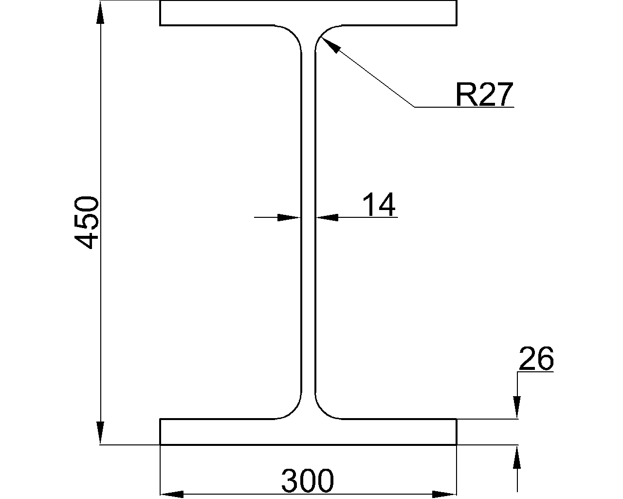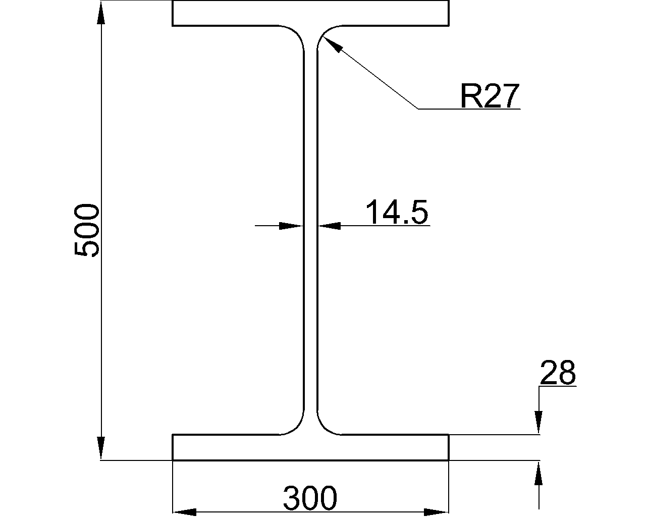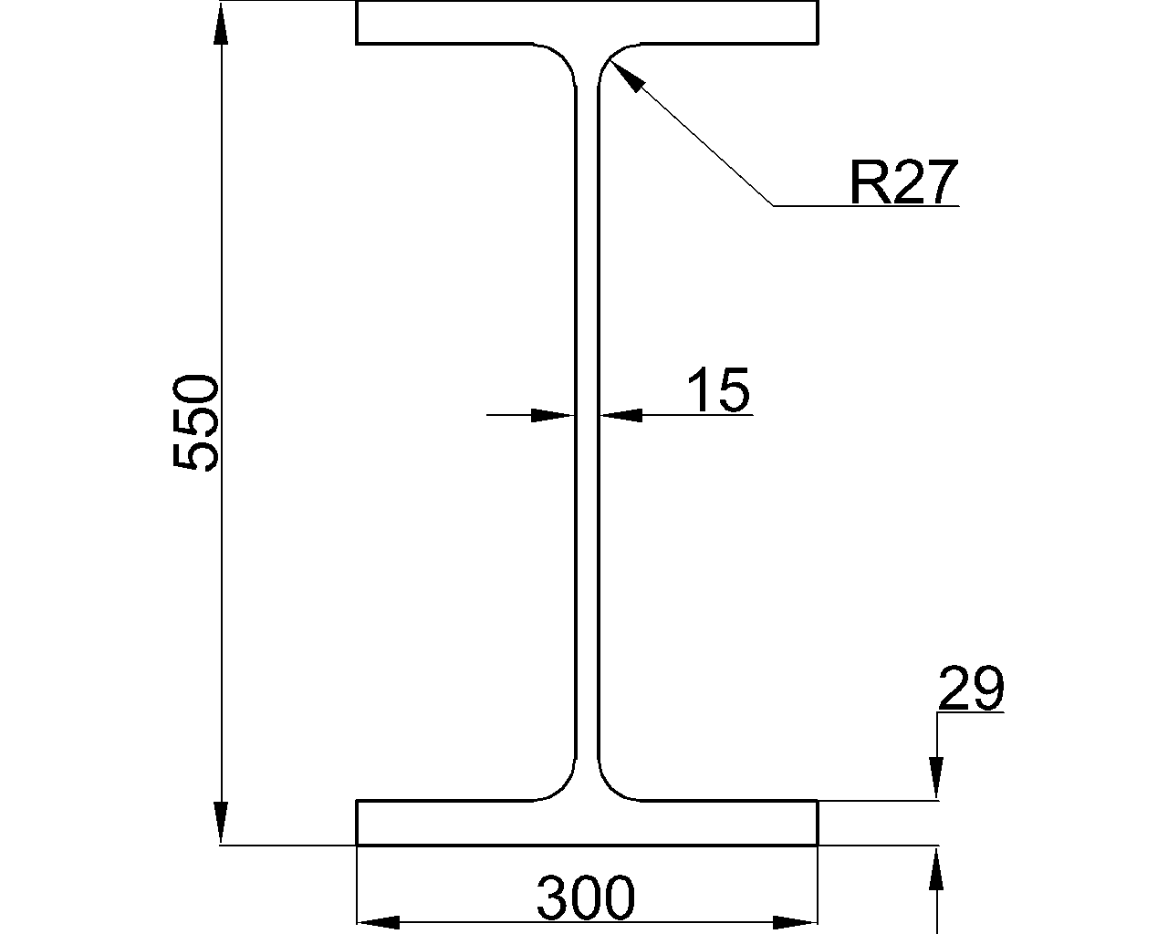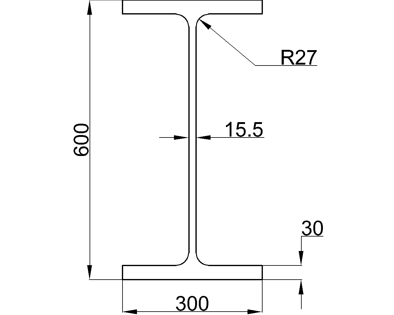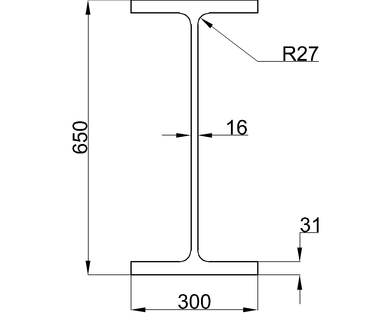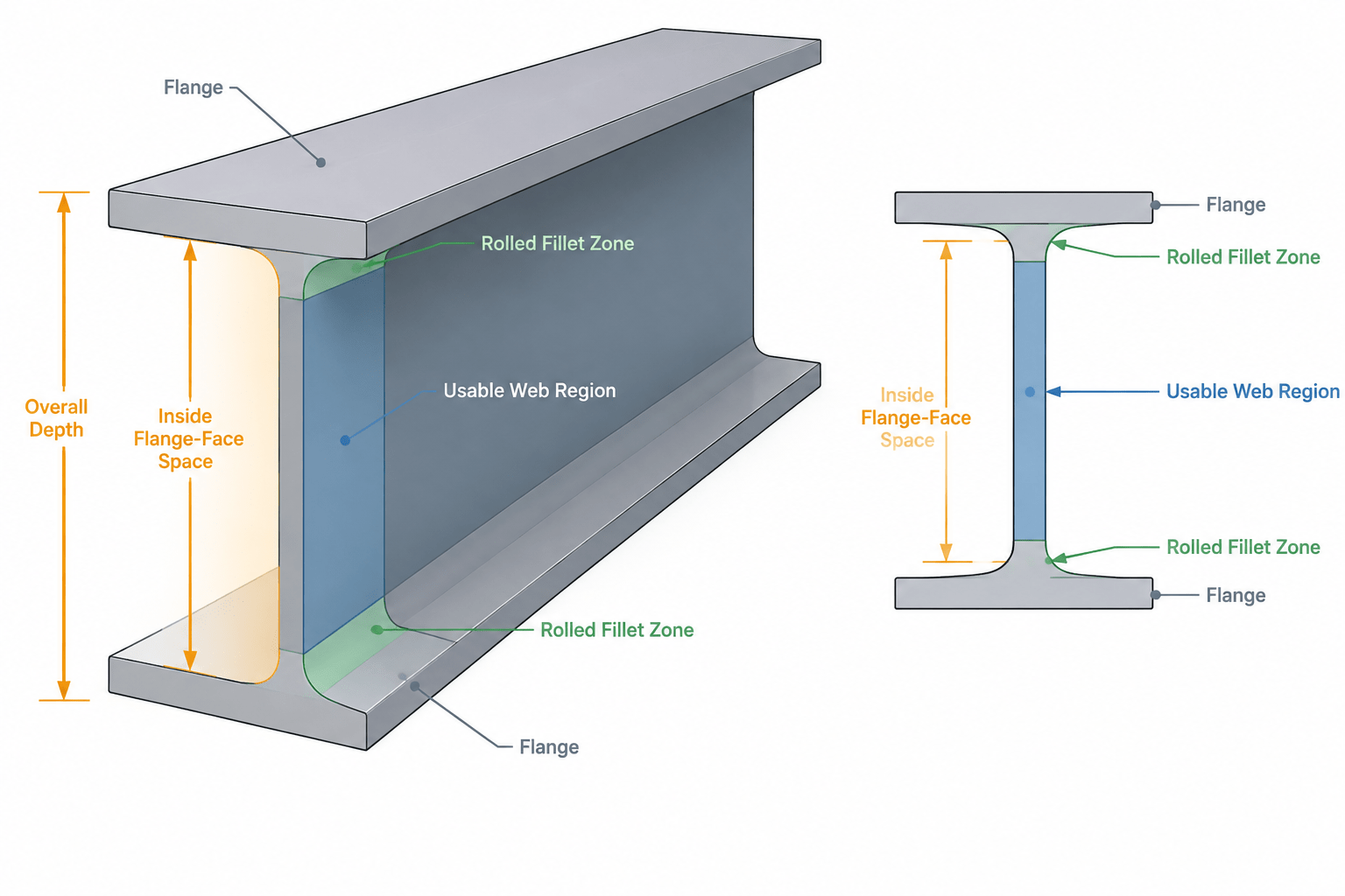
A W-shape may appear to provide a simple rectangular space between its flanges, but that space is not completely available for connection material. Rolled fillets occupy the web-to-flange corners, and practical detailing may require additional clearance for welds, plate edges, bolt installation, and fabrication tolerances. Understanding clear web depth helps drafters and designers avoid connection plates, stiffeners, and bolt patterns that fit in a simplified CAD outline but conflict with the actual rolled shape.
Clear web depth should not be confused with the nominal depth in a shape designation or the published overall depth of a section. Each describes a different part of the geometry and serves a different purpose.
What Does Clear Web Depth Mean?
In general terms, clear web depth is the vertical space along the web between the inside surfaces of the flanges. A basic geometric estimate can be formed from the overall section depth and flange thicknesses. However, that estimate reaches into the curved web-to-flange transition and therefore does not describe a fully usable rectangular zone.
For detailing, the more important question is often:
How much straight, unobstructed web is available for the proposed connection or attachment?
The answer depends on what must fit. A shear plate beside the web, a transverse stiffener welded to the web, and a vertical bolt line through the web do not necessarily have the same clearance requirements. Their edges, welds, holes, and installation access interact with the rolled fillets in different ways.
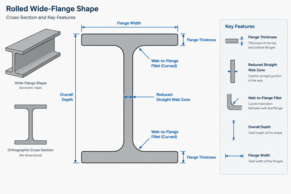
Overall Depth, Flange-to-Flange Space, and Usable Web Zone
| Geometric concept | What it describes | Typical detailing use |
|---|---|---|
| Overall depth | Distance between the outermost flange surfaces | Member depth, elevations, framing coordination, and general section placement |
| Inside flange-face distance | Space between the inner surfaces of the two flanges | Preliminary assessment of material that must fit between flanges |
| Straight web region | Web area between the toes of the rolled fillets | Locating plate edges, weld terminations, holes, and attachments away from curved transitions |
| Required detailing envelope | Space occupied by the connection plus specified clearances | Fit-up, fabrication, erection, and interference checking |
These terms should not be treated as interchangeable. Subtracting two flange thicknesses from the overall depth can describe the nominal distance between flange faces, but it does not remove the fillets from that space. A square-cornered plate modeled to fill the resulting rectangle may collide with the actual section near both ends.
Why Rolled Fillets Matter
Hot-rolled W-shapes do not have sharp internal corners where the web meets the flanges. Each corner has a curved transition produced by the rolling process. This transition improves the continuity of the shape, but it also creates a restricted zone for connection detailing.
The fillet can affect:
- the height and corner treatment of web stiffeners;
- the position of the first and last holes in a vertical bolt group;
- the end shape of shear plates and other connection elements;
- weld access and weld termination locations;
- the fit of clip angles, tees, and built-up connection material;
- automated clash checks based on simplified section profiles.
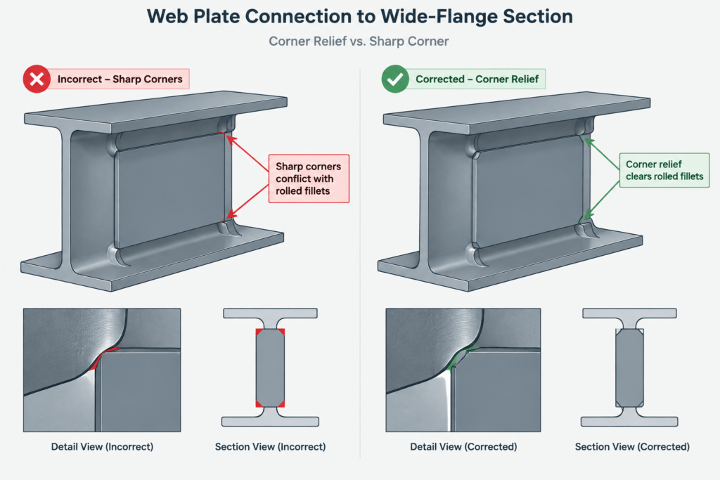
A stiffener extending between flanges, for example, generally cannot be represented accurately as a plain rectangle with sharp corners. Its corners may need to be clipped, coped, radiused, or otherwise detailed to avoid the rolled fillets and accommodate the required weld arrangement. The exact treatment must follow the project design and fabrication requirements rather than a generic drafting assumption.
Using k Dimensions to Understand the Restricted Zone
Structural shape references commonly provide one or more k dimensions associated with the flange-to-web transition. Depending on the table and its purpose, these values help identify the extent of the fillet region or provide a detailing allowance around it.
A vertical k-type dimension is measured from the outside face of a flange toward the web and indicates where the curved transition ends. Considering that dimension from both flanges gives a more useful picture of the straight web region than flange thickness alone.
Do not assume that every table uses the same k symbol or definition. Design-oriented and detailing-oriented values may differ, and reference databases may label related dimensions differently. Before using a value:
- read the table heading and dimension definition;
- confirm whether the value is nominal, design-oriented, or intended for detailing;
- verify that the table applies to the selected shape and product form;
- avoid scaling a section image to recover a missing dimension.
The k region is not simply an optional visual refinement. It represents physical steel that can interfere with a plate edge, weld, or tool path.
Clear Web Depth for Bolt Layouts
A bolt pattern through a W-shape web must fit within more than the section outline. The detailer needs to consider the hole diameter, required edge or end distances within the connected material, connection geometry, bolt installation access, and the proximity of the rolled fillets.
The center of an end hole should not be located by merely dividing the apparent flange-to-flange opening. Instead, establish the permitted connection zone from verified section geometry and the requirements shown in the design documents. Then check the complete hole boundary and associated hardware, not just the bolt centerline.
This distinction becomes especially important when a vertical bolt group nearly fills the available web. A pattern can look acceptable when drawn as points but fail once holes, washers, plate edges, and fillet envelopes are displayed.
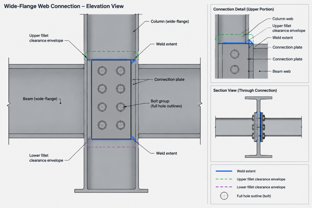
Clearance for Plates, Stiffeners, and Welds
Shear plates and connection plates
A plate attached to the web may terminate below the upper fillet and above the lower fillet, or it may use shaped corners where permitted by the connection design. Its fit also depends on whether it is shop welded, field bolted, or part of another connection arrangement.
Transverse stiffeners
Stiffeners often approach the flanges more closely than ordinary web plates. Their corner geometry, bearing condition, weld layout, and relationship to the flange surfaces must be explicitly detailed. A generic fillet clearance should not be assumed to satisfy structural design requirements.
Weld placement
Weld symbols describe the required joint, but the modeled geometry still needs enough room for the joint configuration and fabrication process. Welds crowded into rolled fillets can create access and fit-up problems. Connection design, welding requirements, and fabricator practices should control the final arrangement.
A Practical CAD Checking Workflow
- Confirm the exact member designation. Do not substitute a nearby nominal depth or a generic wide-flange block.
- Obtain verified section dimensions. Use the applicable shape reference for overall depth, flange thickness, web thickness, and relevant fillet or k information.
- Model the section at full size. Maintain consistent imperial or metric units and avoid scaling by eye.
- Display a fillet clearance envelope. If the CAD profile omits true curves, add construction geometry representing the restricted corner zones.
- Draw complete connection geometry. Include plate boundaries, actual hole outlines, weld extents, and hardware envelopes where coordination requires them.
- Check both ends of the available zone. Verify upper and lower flange interference rather than checking only the nearest corner.
- Review adjacent objects. Deck, slab, piping, fireproofing, seats, clip angles, and neighboring members may further limit access.
- Label assumptions. If fillets or clearances are diagrammatic, identify them as such and require verification before fabrication.
Common Drafting Errors
- Using nominal designation depth as the actual overall depth.
- Subtracting flange thicknesses and treating the result as fully usable web height.
- Drawing sharp internal corners for a rolled W-shape without a clearance envelope.
- Checking bolt centers while ignoring hole edges and hardware.
- Scaling fillet geometry from a catalog image or PDF preview.
- Reusing a connection block after changing the supporting or supported shape.
- Assuming that a plate fitting in the model automatically satisfies design, welding, or fabrication requirements.
Clear Web Depth Is a Fit Check, Not a Capacity Check
Clear web depth is primarily a geometric and detailing concept. Establishing that a plate or bolt group fits within the straight web region does not demonstrate that the member or connection has adequate strength. Web yielding, rupture, buckling, block shear, bolt behavior, weld strength, local flange effects, and other limit states require engineering evaluation using the governing project criteria.
The best workflow separates these tasks without disconnecting them: verified section geometry defines the available physical space, connection design defines what must be provided, and detailing confirms that the designed components can be fabricated and assembled without interference. That approach turns clear web depth from a rough subtraction into a reliable coordination tool.