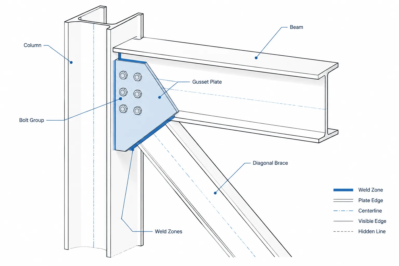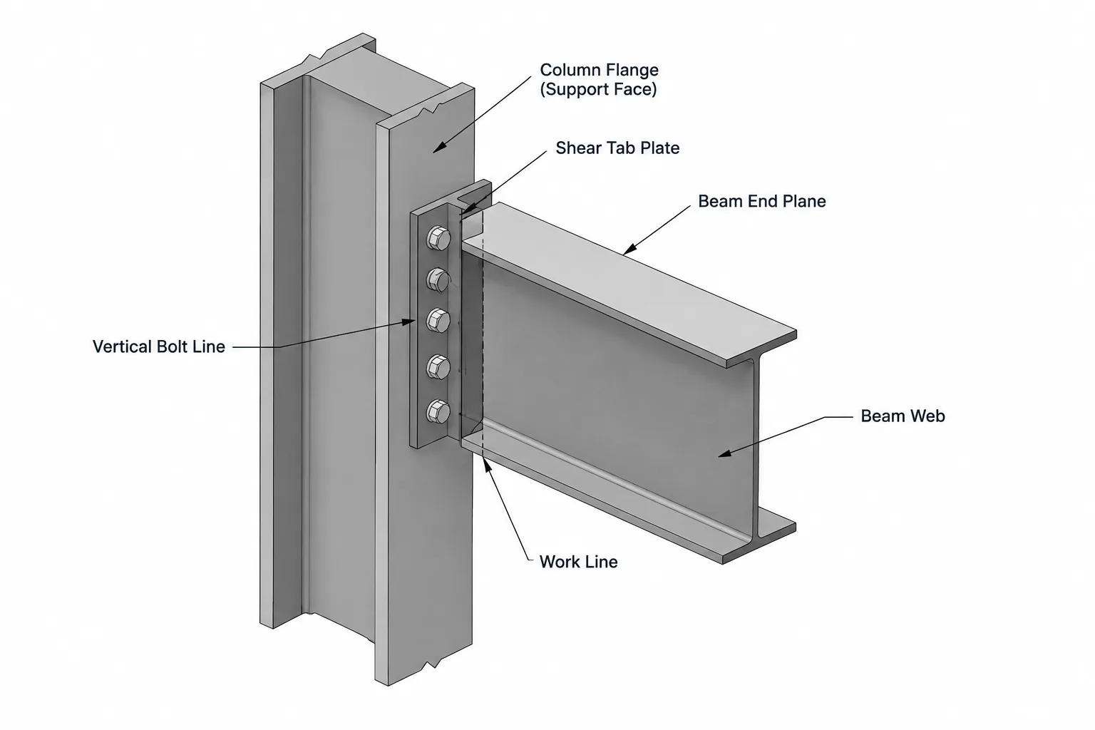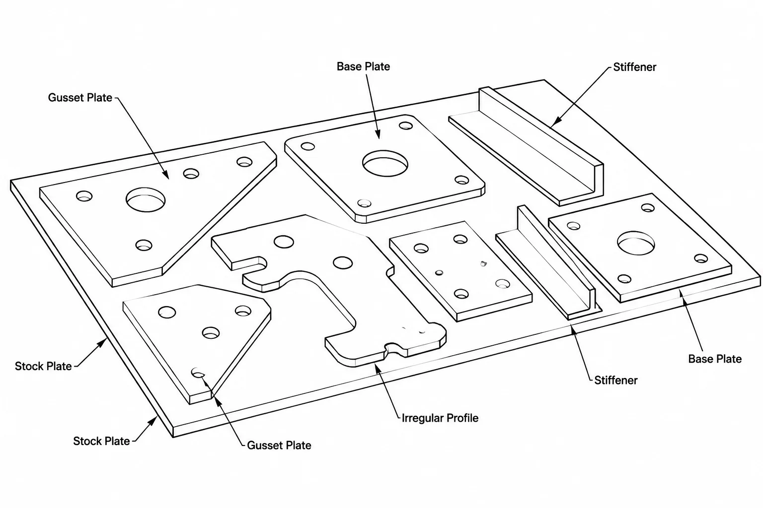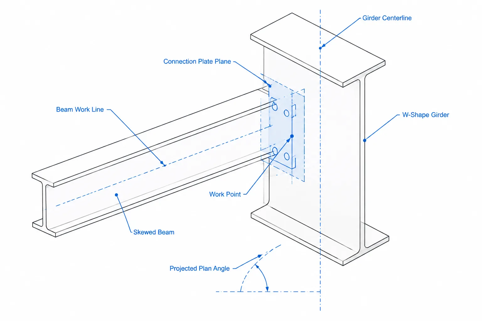
A steel shape CAD profile may look correct on screen while still containing geometry that causes trouble later. Disconnected endpoints can prevent region creation, overlapping arcs can distort calculated area, and an unexpected insertion point can shift a member when the shape is replaced. These problems become especially important when a profile is used for section-property calculations, solid modeling, drawing automation, clash checks, or data exchange.
Cleaning a profile is not the same as approving it for fabrication. A visually accurate section outline may still lack the verified dimensions, tolerances, material information, and process-specific data required for production. The practical goal is to create controlled CAD geometry whose source, purpose, units, orientation, and limitations are clear.
Start by Defining the Profile’s Intended Use
Not every drawing needs the same level of section detail. Before editing the geometry, determine what the profile is expected to do.
| Intended use | Geometry commonly needed | Primary concern |
|---|---|---|
| Diagrammatic framing plan | Centerlines or simplified outlines | Readable member location and orientation |
| General arrangement model | Recognizable section envelope | Overall size, placement, and clash detection |
| Connection detail | Relevant faces, thicknesses, and root regions | Plate fit, bolt access, weld access, and clearances |
| Section-property calculation | Verified closed cross-sectional boundary | Area distribution, axes, and radii |
| Manufacturing data | Process-ready geometry from an approved workflow | Verification, tolerances, machine rules, and release control |
A simplified W-shape can be entirely appropriate in a small-scale framing drawing but unsuitable for calculating section properties. Conversely, a highly detailed rolled fillet can add visual clutter and file complexity where only the member envelope is needed.
Verify Units and Overall Size Before Cleaning
Geometry cleanup should begin with a dimensional check, not with trimming and joining. Identify whether the source profile was created in inches, feet, millimeters, or another drawing unit. Do not assume that a block inserted at a convenient scale is dimensionally correct.
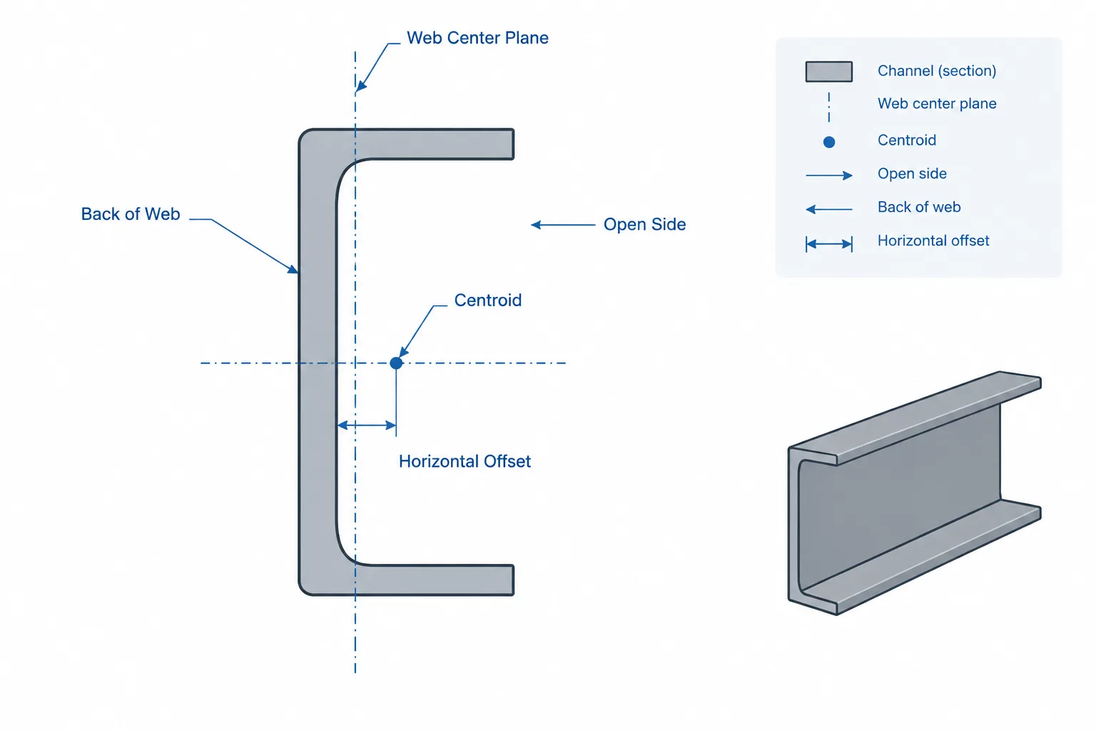
Measure several independent features and compare them with a verified shape reference. For a W-shape, useful checks may include overall depth, flange width, web thickness, and flange thickness. For rectangular or square HSS, check overall outside dimensions and wall representation. For a channel or angle, verify both the overall envelope and the direction of the open side or unequal legs.
Checking more than one dimension helps reveal profiles that have been stretched, nonuniformly scaled, or reconstructed from an image. A section can match its nominal depth while still having incorrect flange or wall geometry.
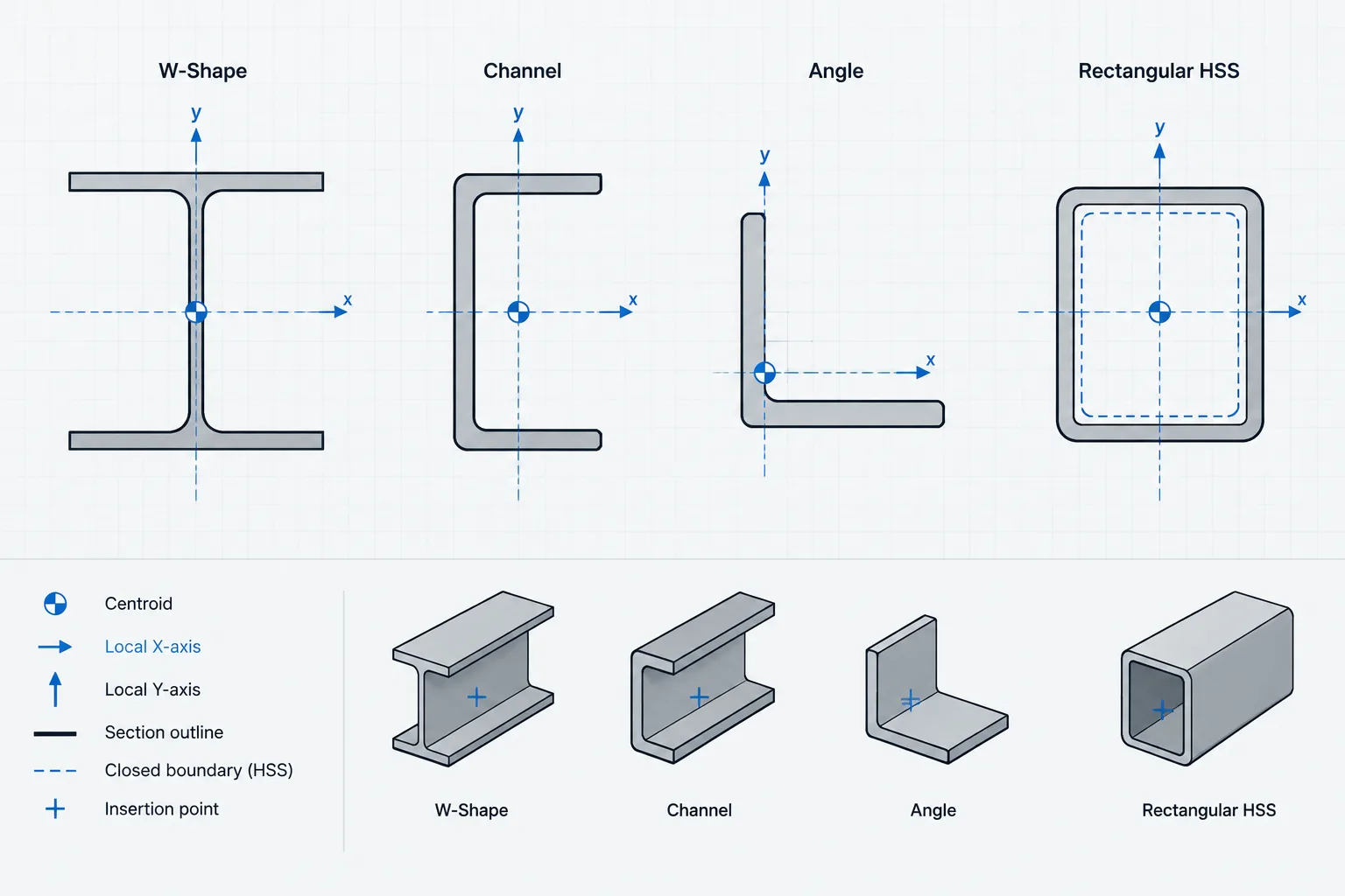
Choose and Document a Consistent Origin
A clean profile needs a predictable reference point. Common origins include the section centroid, the intersection of member centerlines, the back of a channel web, an HSS centerline, or a convenient bounding-box corner. No single origin is ideal for every task.
- Centroid origin: Useful for section-property work and analytical alignment.
- Geometric center origin: Convenient for doubly symmetric shapes and many modeling operations.
- Face-based origin: Helpful when steel must be located from a web back, flange face, or HSS face.
- Corner origin: Convenient for library organization, but less descriptive of structural placement.
The insertion point and the geometric origin should not be confused. A block can have an insertion point far from its visible profile, and copied geometry may retain coordinates unrelated to the steel section. Place the chosen reference deliberately and record it in the block name, layer convention, library notes, or accompanying metadata.
Inspect the Entity Structure, Not Just the Appearance
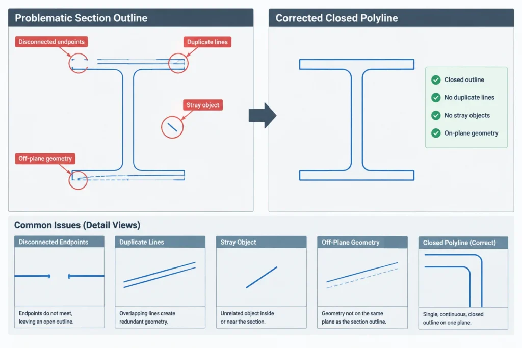
Zooming in is useful, but visual review alone does not establish that a boundary is valid. Inspect the entity types and connectivity.
Disconnected endpoints
Lines and arcs that appear to meet may have small gaps. Such gaps can prevent the creation of a closed region or produce unexpected results when the profile is extruded. Endpoint checks, object snaps, boundary tools, and temporary markers can help locate breaks.
Overlapping and duplicate entities
Duplicate lines are common when profiles are assembled from mirrored geometry or copied between drawings. They may be invisible until an entity is selected or deleted. Overlaps can interfere with trimming, hatching, area calculations, and file translation.
Zero-length and stray objects
A profile may contain tiny line segments, isolated points, construction lines, or text fragments. These objects increase file noise and may enlarge the apparent extents of a block. A distant stray entity can also make zoom-to-extents appear as if the section has disappeared.
Inconsistent elevation
A nominally two-dimensional profile can contain entities at different elevations. They may look aligned in plan while refusing to form a planar boundary. Confirm that section-outline entities lie in the intended plane before joining them.
Build Boundaries That Match the Shape Type
Closed geometry behaves differently for open and hollow steel sections.
W-shapes, channels, angles, tees, and HP shapes
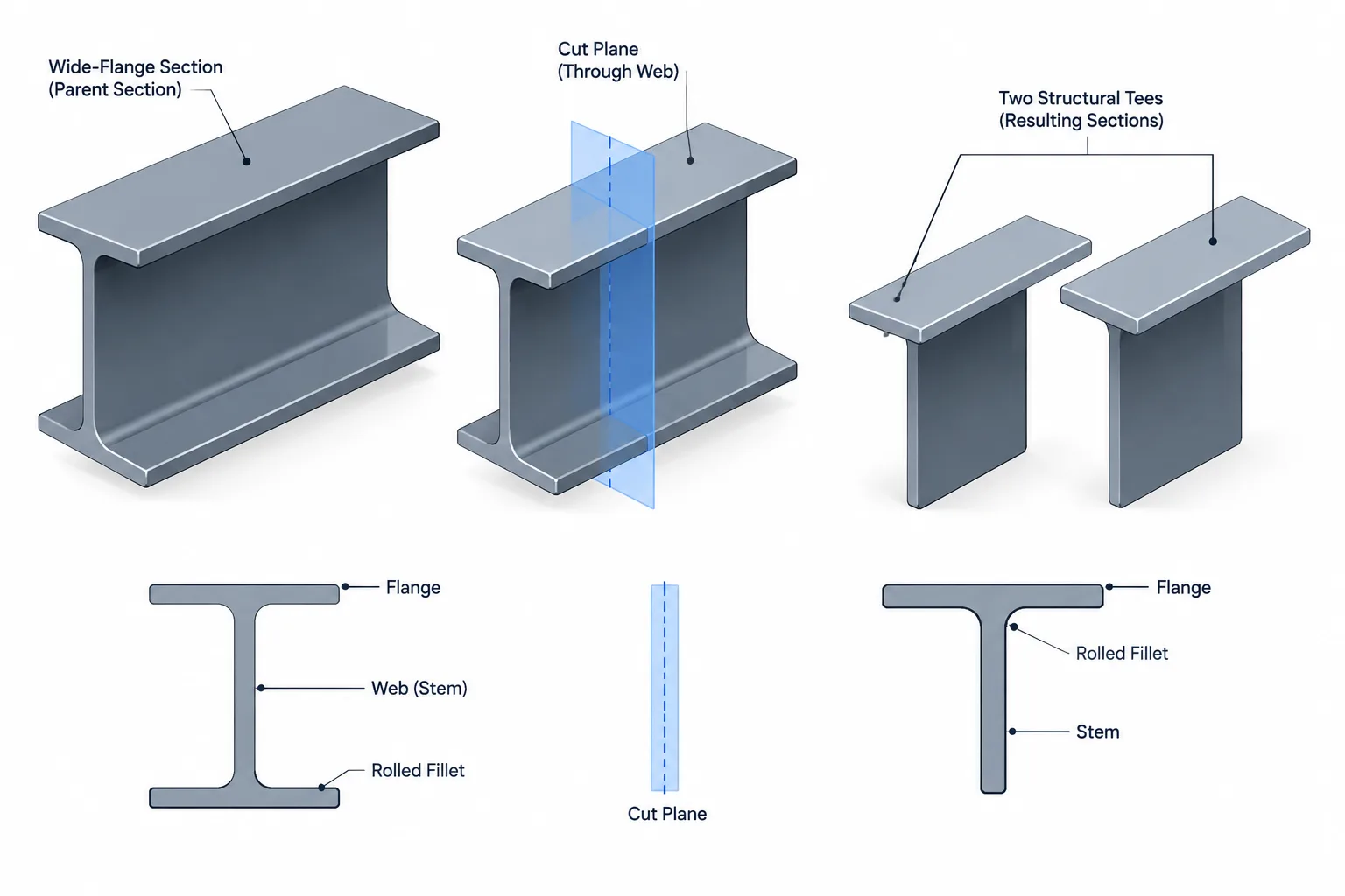
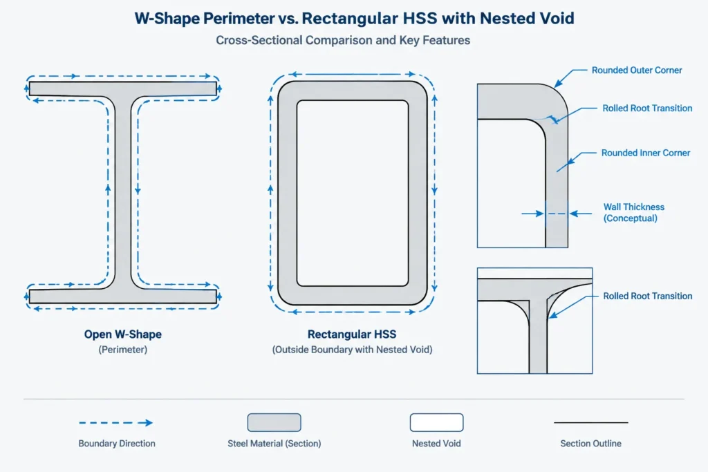
These open sections normally use one continuous perimeter describing the steel material. The path follows outside edges, flange tips, flange surfaces, web surfaces, and root transitions. If rolled fillets are represented, the arcs should be tangent or otherwise consistently connected to adjacent faces.
A common mistake is to draw separate flange and web rectangles that overlap. The result may look like a section but contains internal boundaries and duplicated material. That construction can produce an incorrect area unless the components are combined correctly.
HSS and other hollow sections
A hollow profile needs an outside boundary and an inside boundary. Both must be closed, correctly nested, and located in the same plane. The interior loop represents the void and must not be treated as another solid region.
Rounded HSS corners require particular care. A generic corner radius chosen for appearance should not be assumed to reproduce a published section or its properties. If the CAD outline must support calculations or close-fit detailing, use verified geometry appropriate to that purpose.
Decide How to Represent Rolled Fillets and Corners
Rolled shapes are not assembled from perfectly sharp rectangles. W-shapes, channels, angles, tees, and similar sections include transitions at flange-web or leg junctions. HSS has rounded outside and inside corners rather than mathematically sharp corners.
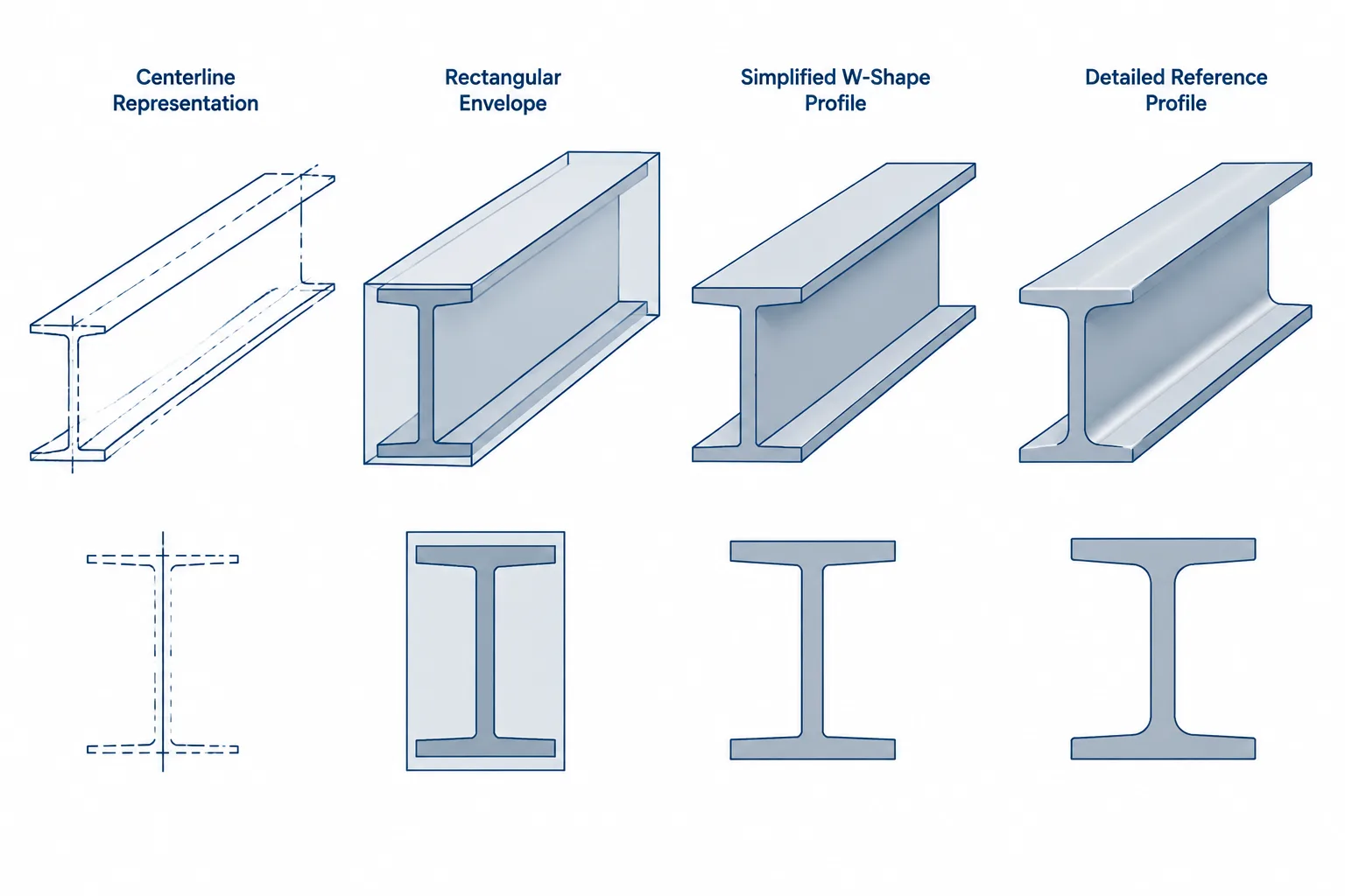
Three representation levels are common:
- Envelope geometry: Captures overall dimensions but omits local radii and thickness detail.
- Simplified section geometry: Shows flange, web, leg, or wall thickness with idealized corners.
- Detailed profile geometry: Includes verified or purpose-appropriate transitions and radii.
The selected level should be stated rather than implied. A simplified profile can be useful for layout while being unsuitable for local fit-up near a rolled fillet. Adding an approximate arc does not automatically make a profile more accurate.
Check Symmetry Without Forcing It
Symmetry is a powerful CAD quality check, but only when the section is actually symmetric about the selected axis. W-shapes and many HSS sections are commonly modeled with clear symmetry relationships. Channels, angles, and many tees are not symmetric about both principal drawing axes.
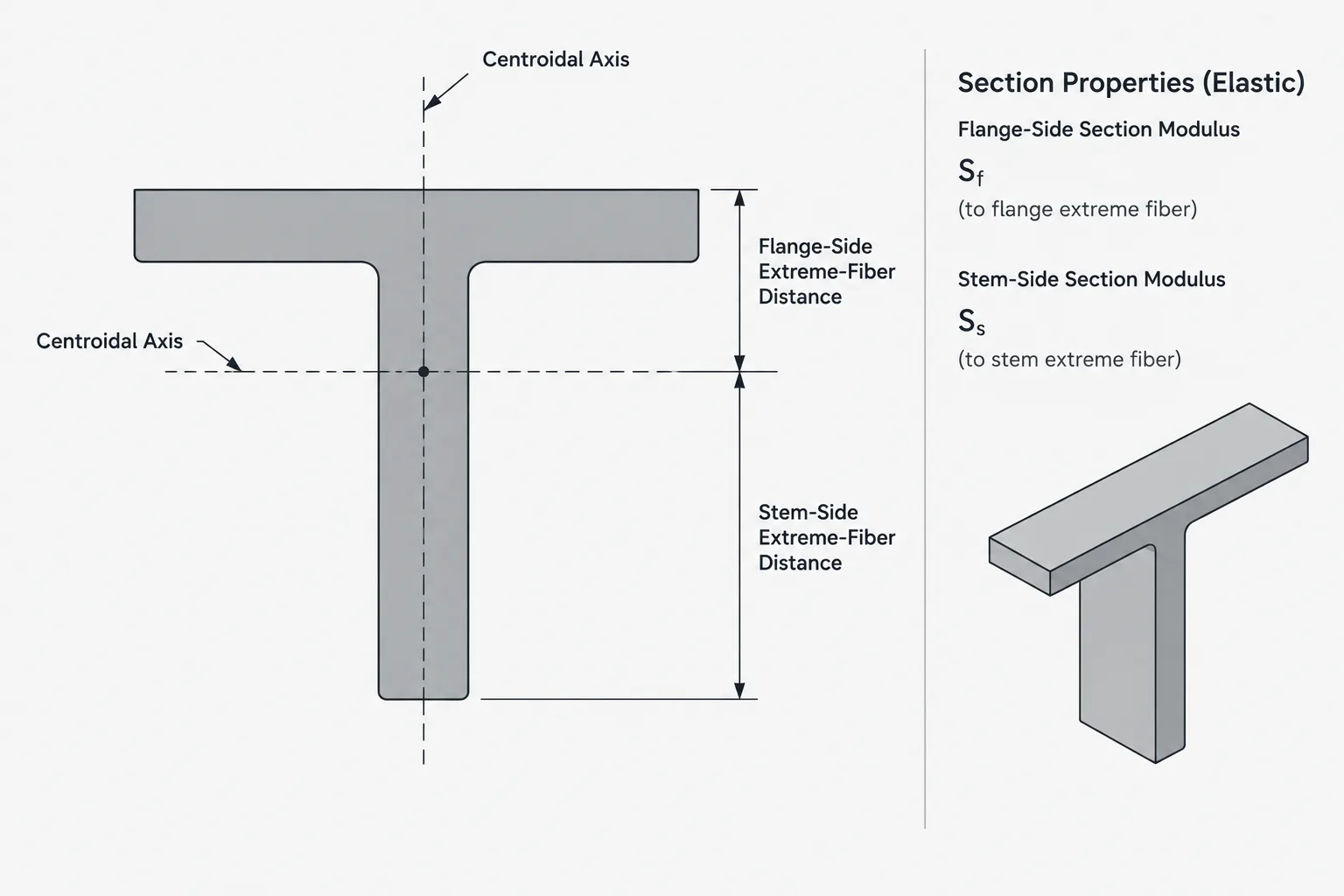
For a symmetric profile, compare mirrored flange tips, web faces, wall boundaries, and arc endpoints. Unexpected differences may reveal a trimming error or an inaccurate reconstruction. For an unsymmetric section, do not move the profile to make the centroid coincide with the center of its bounding box. The centroid location is a section property, not a visual preference.
Use Area and Centroid as Diagnostic Checks
Once a calculation-grade boundary has been created, CAD-derived area and centroid can serve as useful diagnostic values. They should be compared with verified section data using consistent units and axes.
A mismatch does not immediately prove that the table or drawing is wrong. Possible causes include simplified fillets, nominal wall geometry, duplicate regions, an incorrectly interpreted interior void, or differences between idealized and published shape definitions. Treat the comparison as an investigation tool rather than a reason to alter geometry until the values happen to agree.
The same caution applies to moments of inertia and section moduli. These properties are sensitive to material distribution, so small-looking geometry changes near outer fibers can have more influence than expected.
Create a Repeatable CAD Quality-Control Sequence
A consistent checklist makes profile libraries easier to maintain:
- Identify the shape designation and the source used for verification.
- Confirm drawing units and measure several independent dimensions.
- Establish the intended section orientation and local axes.
- Set a deliberate origin and block insertion point.
- Remove duplicate, stray, zero-length, and off-plane entities.
- Close all required loops and verify interior voids.
- Confirm that arcs and line segments connect as intended.
- Check symmetry only where symmetry belongs.
- Compare area, centroid, or other properties when the geometry is intended for calculation.
- Label the profile as diagrammatic, simplified, detailed, or process-specific.
- Test the profile after export or translation into the receiving workflow.
Keep the untouched source file separate from the cleaned library version. If a profile changes, record what changed and why. That prevents an unverified edit from silently replacing a known reference.
A Clean Profile Is Controlled Geometry, Not Automatic Approval
The best steel shape CAD profile is not necessarily the one with the most entities. It is the one whose dimensions, boundaries, origin, orientation, and intended use are understood. A lightweight envelope may be ideal for coordination, while a verified closed profile may be needed for calculations or modeling.
Before a profile influences connection fit, section properties, fabrication, or ordering, confirm it against the governing project information and an appropriate steel shape reference. CAD cleanup improves reliability, but it does not replace engineering review, detailing checks, fabrication requirements, or formal release procedures.