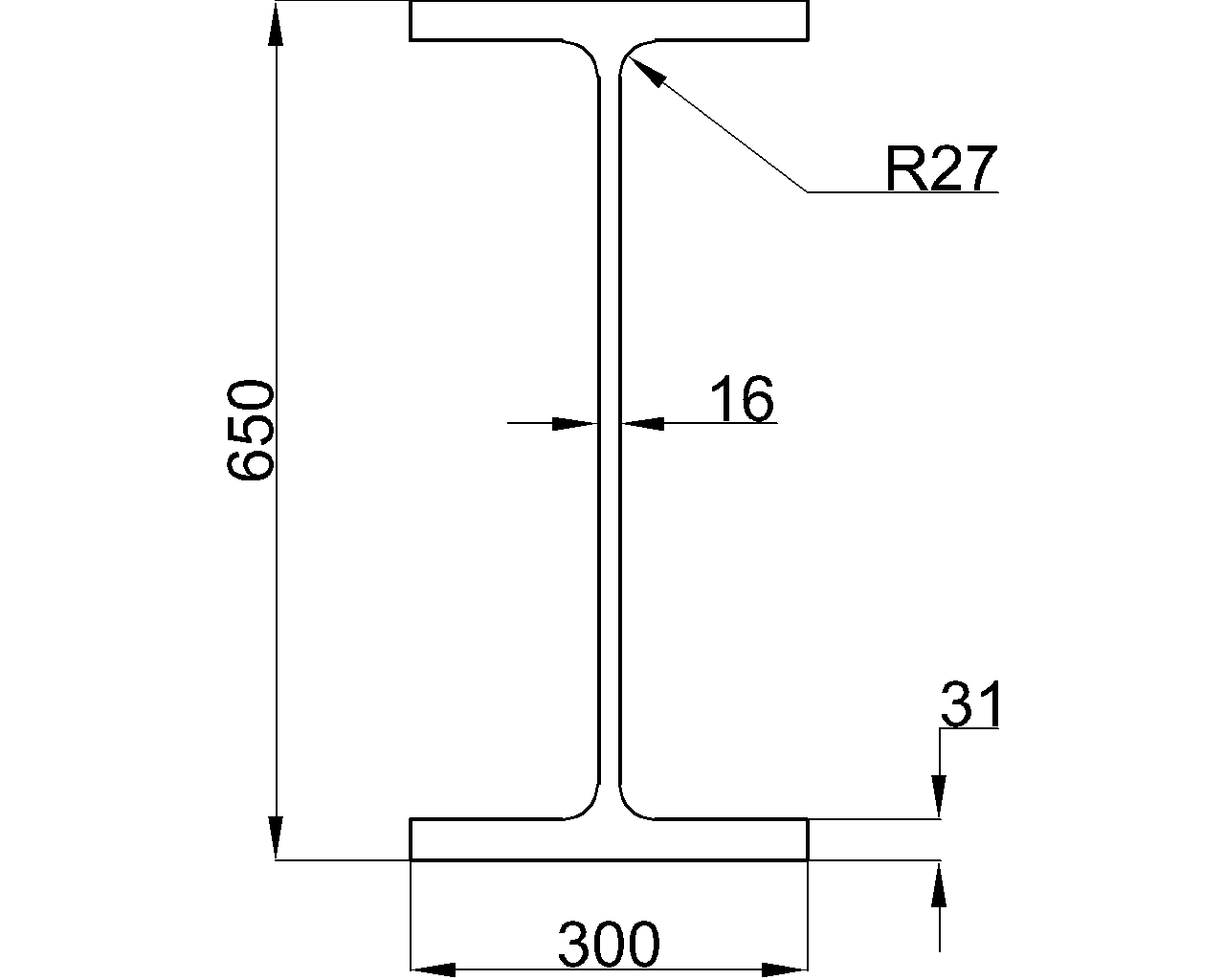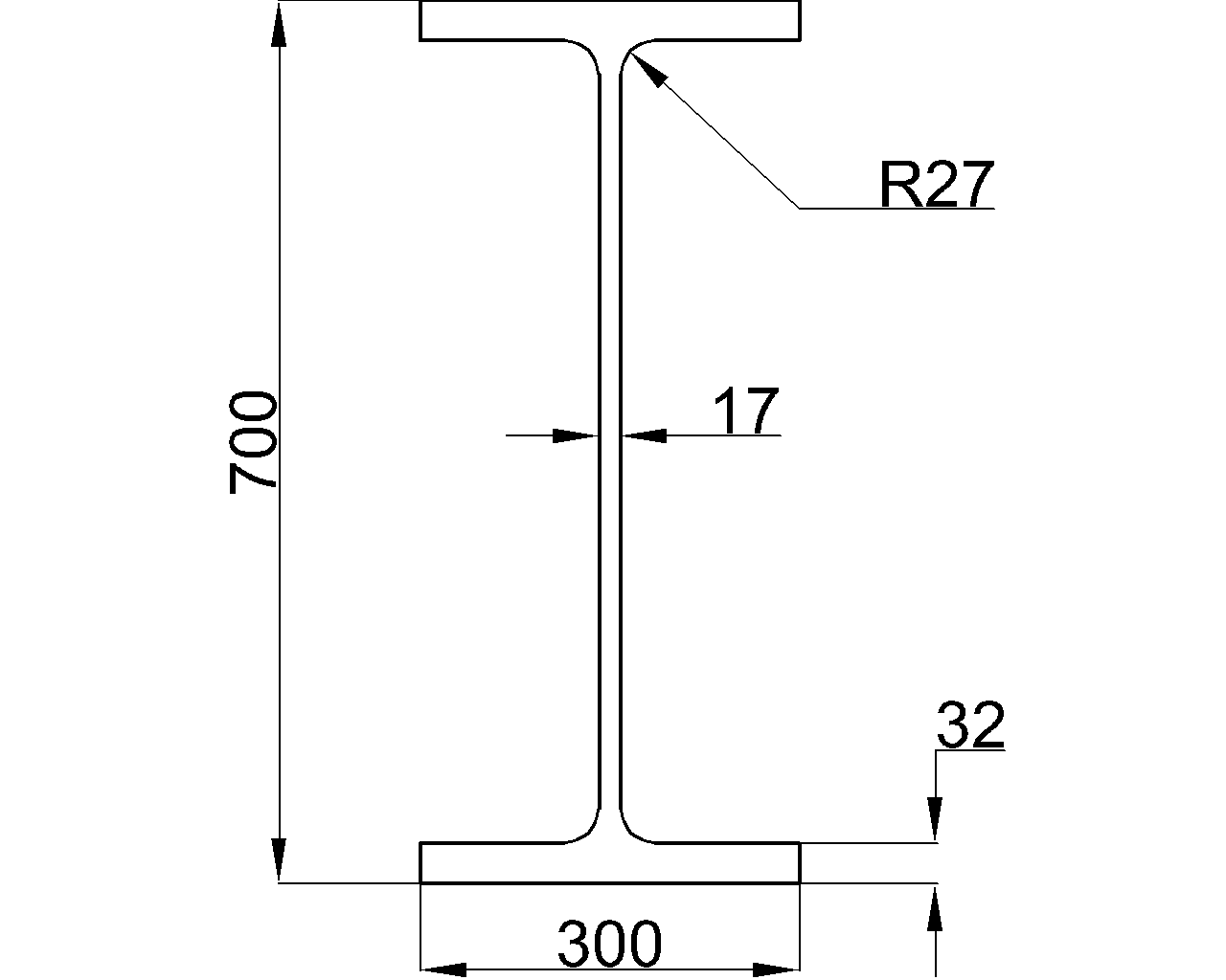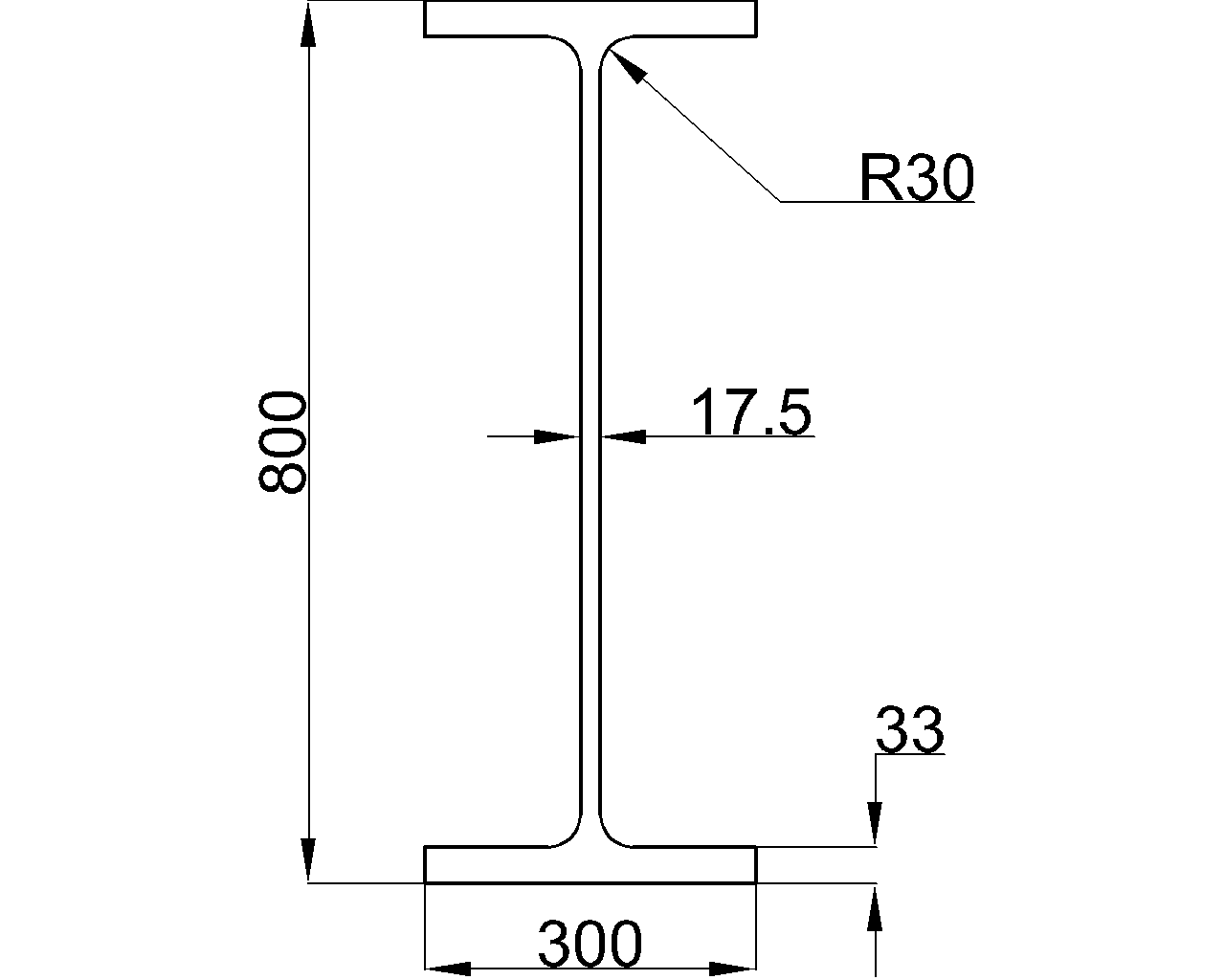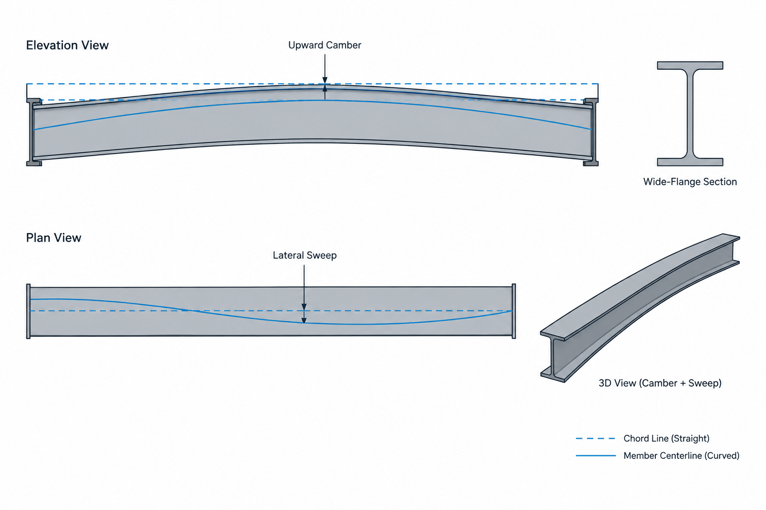
A steel member that does not appear straight may have intentional camber, lateral sweep, ordinary permitted variation, or deformation introduced during fabrication, handling, or erection. These conditions can look similar in an isolated view, but they describe different geometry and can affect connections, elevations, cladding, decking, and field fit in different ways.
For drafters and detailers, the central question is not simply whether a member is curved. It is which direction the deviation occurs, what reference line controls it, and whether the curvature is intentional. Clear terminology prevents a cambered beam from being modeled as a sloping beam or a swept member from being mistaken for one with an incorrect plan location.
Camber, sweep, and out-of-straightness compared
Camber and sweep are directional descriptions. They are normally evaluated relative to the member’s intended longitudinal axis and its installed orientation.
| Term | Typical meaning | Common drawing view | Primary concern |
|---|---|---|---|
| Camber | Curvature in the member’s principal bending plane, often intentionally induced upward in a beam | Elevation | Floor elevation, deflection allowance, deck support, and connection fit |
| Sweep | Sideways curvature perpendicular to the usual camber plane | Plan | Grid alignment, framing fit, cladding lines, and lateral clearance |
| Out-of-straightness | A general description of deviation from a straight reference line | Plan, elevation, or both | Acceptance, fit-up, stability assumptions, and fabrication quality |
| Slope | A straight member axis intentionally inclined between endpoints | Elevation or plan | End elevations, framing angles, and connection geometry |
| Rotation or twist | Change in cross-section orientation along the member | Sections and three-dimensional views | Flange position, bearing surfaces, and connection alignment |
These conditions can occur together. A roof beam may be intentionally sloped, specified with camber relative to its sloping chord, and also have some lateral sweep. A complete description therefore needs both orientation and a defined reference.
Camber is curvature, not member slope
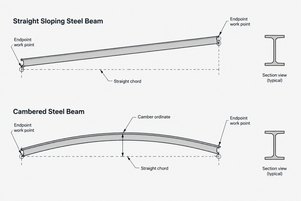
A sloping beam can still be geometrically straight. Its endpoints lie at different elevations, but its longitudinal reference axis follows a straight line. A cambered beam departs from the straight chord connecting its reference endpoints.
This distinction is especially important in elevation drawings. If the center of a cambered beam is higher than a straight line between its ends, that rise is not automatically an added end elevation. The end work points may remain unchanged while the member curves between them.
Camber is commonly used to offset part of the anticipated downward movement associated with loading, but its purpose and required value are engineering decisions. A detailer should not calculate, add, remove, or reinterpret camber without the controlling design information. Likewise, an observed curve in an existing member should not automatically be labeled as specified camber.
The chord and camber ordinate
Camber is generally communicated as a deviation from a straight chord. The chord is an imaginary straight reference between defined points on the member. The camber ordinate is the perpendicular distance from that chord to a designated location on the member, commonly near the region of maximum curvature.
The drawing or project convention should make clear:
- which points define the chord;
- whether the reference follows the member centerline, a flange surface, or another datum;
- where the ordinate is measured;
- which direction is considered positive camber; and
- whether the stated condition applies before or after erection.
A single camber value does not necessarily define a circular arc. Actual camber may not follow a constant radius, and fabrication methods do not automatically produce mathematically perfect arc geometry. Unless a required profile or radius is specifically defined, a CAD model should not invent one.
Sweep is best understood in plan
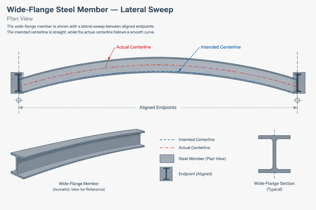
Sweep is lateral deviation from a straight line along the member. For a conventionally oriented W-shape beam, camber is usually visible in elevation while sweep is visible in plan. Rotating the member can make those labels less intuitive, so the member’s local axes and installed orientation should always be considered.
A swept member may have correctly located ends but bow sideways between them. This can create practical conflicts even when the end connections fit. Possible effects include reduced clearance to adjacent framing, offset deck edges, misaligned girts, interference with façade supports, or difficulty maintaining a straight architectural line.
Sweep should not be confused with an intentional plan angle. A diagonal beam connecting two grid intersections can be perfectly straight. Its centerline is simply not parallel to the primary grids. Sweep exists when the member departs laterally from its intended straight chord.
Orientation controls the terminology
Terms such as upward, downward, and sideways depend on how the member will be installed. A loose member may be rolled over, stored on its side, or viewed from either end. What appears to be vertical curvature in the shop may become lateral curvature after erection.
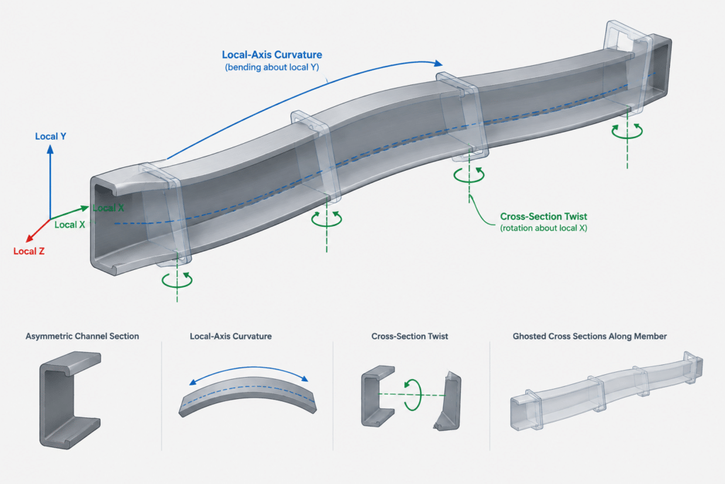
Useful documentation identifies the member and its orientation rather than relying only on screen coordinates. References may include the top flange, north side, grid side, outstanding leg, near end, far end, or designated local axes. The same discipline is useful for channels, angles, structural tees, and built-up members, where the cross section may not have two obvious planes of symmetry.
For asymmetric shapes, curvature can also interact with twist. A channel that bows laterally while its cross section rotates cannot be described adequately by one sweep dimension. Sections or survey points may be needed to distinguish translation from rotation.
How camber and sweep are measured conceptually
Both conditions require a reference line. The basic workflow is to establish the intended chord, identify the member line or surface being checked, and measure the maximum relevant deviation between them. The actual inspection method depends on the member, access, fabrication stage, and governing project requirements.
Several details can change the reported result:
- Reference endpoints: Overall member ends, work points, bearing points, and cut ends are not always the same locations.
- Reference feature: Measurements taken at a flange edge may include local flange variation or twist that is not present at the member centerline.
- Support condition: A member’s measured shape can change depending on how it is supported and oriented.
- Temperature and handling: Field and shop conditions can influence observed geometry.
- Applied load: Self-weight, attachments, stored materials, and construction loading can affect an elevation reading.
Because of these variables, a drawing note should not mix specified geometry with an undocumented field measurement. If an existing condition is being recorded, identify the datum, measurement direction, support condition, and locations checked.
Practical CAD and detailing workflow
Keep design references separate from display geometry
Start with straight work lines between the controlling endpoints. These lines preserve grids, work points, slopes, and connection references even if a curved representation is later added. Place any displayed camber or sweep geometry on a separate layer, object class, or model category where the workflow permits.
This separation helps prevent dimensions from snapping to a graphic curve when they should reference the member’s design chord. It also makes it easier to distinguish intended geometry from a diagram that has been exaggerated for clarity.
Do not infer curvature from a symbolic view
Camber is often shown schematically because true-scale curvature may be difficult to see on a framing elevation. A visibly curved line should not be treated as a scaled fabrication profile unless the drawing explicitly establishes that use.
Similarly, do not convert a stated camber ordinate into a radius without sufficient geometric definition. Multiple curve shapes can share the same endpoints and maximum ordinate.
Coordinate connection details with the fabrication approach
End connections are often controlled by straight work lines and end work points, but attachments located along a cambered member may be affected by the curved geometry. Stiffeners, shear connectors, deck supports, kickers, bridging, and secondary framing may require coordination.
The detailer should verify whether intermediate attachments are located from the chord, from the actual member surface, or from project elevations. Do not assume that all connection plates remain square to a curved member or that every attached component follows the camber profile.
Use unambiguous notes
A useful note identifies the member, direction, reference, and intended condition. Avoid vague instructions such as curve beam upward or bow as required. When the design documents do not provide enough information, request clarification rather than filling the gap with a CAD assumption.
Common detailing mistakes
- Adding camber to the endpoint elevations instead of treating it as deviation from the chord.
- Modeling a sloped member as curved because its ends have different elevations.
- Assuming a drawn arc defines the actual fabrication radius.
- Calling all visible lateral offset sweep without checking grids, work points, and intentional plan geometry.
- Measuring from a flange edge without accounting for twist or local variation.
- Using global vertical and horizontal directions when the member’s local orientation controls the description.
- Removing a specified camber note because the analysis or modeling line is straight.
- Applying project acceptance criteria from memory instead of consulting the governing documents and applicable standards.
A clear review sequence
When reviewing a member that appears curved, first confirm its designation and installed orientation. Next, establish the intended straight chord between the controlling points. Check the elevation for curvature in the primary bending plane, then check the plan for lateral deviation. Review cross-section orientation at multiple locations if twist is possible. Finally, compare the observed or modeled condition with the design notes, shop requirements, and governing project criteria.
Camber and sweep are simple ideas, but they become ambiguous when reference lines and orientations are omitted. Keeping the chord, work points, member axes, and displayed curvature separate produces clearer drawings and more reliable coordination among designers, fabricators, erectors, and field inspectors.